 Open Access Article
Aligned Fe3O4 magnetic nanoparticle films by magneto-electrospray method
Christina W. Kartikowatia,
Qing Liab,
Shinji Horiec,
Takashi Ogi *a,
Toru Iwakia and
Kikuo Okuyamaa
aDepartment of Chemical Engineering, Graduate School of Engineering, Hiroshima University, 1-4-1 Kagamiyama, Higashi-Hiroshima 739-8527, Japan. E-mail: ogit@hiroshima-u.ac.jp
bDepartment of Environmental Science and Engineering, Fudan University, Shanghai 200-433, China
cTechnical Strategy Department, Research and Development Division Toda Kogyo Corporation, Otake, Hiroshima 739-0652, Japan
First published on 16th August 2017
Abstract
This work reports for the first time the preparation and evaluation of aligned Fe3O4 nanoparticle films via a magneto-electrospray method, i.e., electrospray under a magnetic field. The magnetic field was applied to align the magnetic moment of Fe3O4 particles. Well-dispersed Fe3O4 nanoparticles (NPs) with average sizes of 10, 25, and 45 nm were obtained using a bead-mill dispersion. The Fe3O4 nanoparticle slurries were mixed with a polyvinyl alcohol (PVA) solution and then deposited on Si-wafers under a 0.1 T magnetic field. The Fe3O4 crystalline structures were maintained after both dispersion and deposition, as characterized by X-ray diffraction patterns. Hysteresis curves revealed that the magnetic coercivity (Hc) of the well-dispersed nanoparticle slurries decreased owing to magnetic interactions among particles. However, the Hc values of the films were larger than those of the nanoparticle slurries. The values further increased from the application of a magnetic field during film deposition. This enhancement was attributed to alignment of the magnetic moments of the Fe3O4 NPs. These results show that tuning of the magnetic properties of materials, such as Fe3O4 NPs, can be achieved by controlling the alignment of their magnetic moment.
1. Introduction
The structuration of magnetic nanoparticles (NPs) into well-defined arrangements and geometries is a requirement for many developing technologies, such as the Internet of Things (IoT).1 Magnetic NPs have unique properties that show great potential for applications in sensors and magnetic data storage.2–4 Although various methods for preparing structured magnetic composites have been developed over the years, the hierarchical arrangement of such structures with control over the composition and alignment of magnetic NPs remains challenging.Fe3O4 NPs possess a strong magnetic moment and good biocompatibility, chemical stability, and magnetoelectric properties.5,6 These materials have been widely studied for potential applications, such as recording media,7 spintronics,8 Li batteries,9 biomedical materials,10 sensors,11 and environmentally friendly technologies.12 These applications would benefit from greater control over the magnetic properties of the materials. Precise control over the magnetic properties of a structured NPs composite is therefore highly desirable. The magnetic properties of a structured magnetic nanoparticle composite can be controlled by aligning their magnetic moment under a magnetic field, as has been reported in our previous studies on α′′-Fe16N2 NPs.13–16 However, well-dispersed NPs are required for this alignment process.
A method for dispersing the NPs in organic solvent is therefore proposed to enable the resulting suspension to mix with polymeric materials related to composite applications. NPs aggregate and agglomerate during the synthesis process, which inhibits their alignment. Our group have succeeded in producing well-dispersed TiO2, BN, and α′′-Fe16N2 NPs, using a low energy bead-mill dispersion,17–19 which had no adverse effects on the NPs shape and structure. Owing to their magnetic interactions, Fe3O4 NPs agglomerate readily. Therefore, dispersion techniques are required to break-up the agglomerates and obtain well-dispersed magnetic NPs prior to their structuration in a magnetic nanoparticle composite.
The formation of Fe3O4 nanoparticle composites in the form of a film is preferable for demonstrating the magnetic alignment process. Several methods have been widely reported for preparing Fe3O4 films including molecular beam epitaxy,20,21 sputtering,22 electrodeposition,23 and pulsed laser deposition.24,25 However, these film preparation methods are not capable of preparing composite films with controlled compositions, structures, and magnetic properties. Thus, it is important to develop preparation methods, which enable control over the Fe3O4 composition, structure, and magnetic properties. Electrospray techniques are considered as a promising method for film deposition from various precursor solutions. Droplets produced by electrospray are highly charged and have a high deposition efficiency.26–29 Electrospray method has also been recently reported to be effective for fabrication of a carbon nanotube forest-like film from a carbon nanotube suspension.30
With the aim of producing structured magnetic Fe3O4 NPs with controllable magnetic properties, this study reports dispersion of Fe3O4 NPs followed by deposition via a magneto-electrospray method. The studied samples included superparamagnetic and single domain Fe3O4 NPs that were produced under well-controlled crystal growth conditions on a large scale. An external magnetic field of 0.1 T was applied during deposition to align the magnetic moment of the Fe3O4 NPs in the films. The effects of the dispersion process on the particle morphology and magnetic properties were evaluated together with the effects of the magnetic field on the morphology and magnetic properties of the deposited films.
2. Experimental
2.1 Materials
The Fe3O4 NPs used in this study had mean size of 10, 25, and 45 nm and were prepared by a large-scale liquid precipitation method with precise control of the Fe2+ concentration, pH, temperature, and aeration rate as described in a patent no. US 5843610 A (Toda Kogyo Co. Ltd, Japan).31 PVA was purchased from Kanto Chemicals, Tokyo, Japan, and was used directly without further treatment or purification.2.2 Dispersion of the Fe3O4 NPs
The initial slurry for dispersion was prepared by mixing 5 g of Fe3O4 NPs with 308.75 g of water and adding 3 mL NH4OH to adjust the pH to ∼9. This slurry was stirred for 30 min prior to dispersion and added to the mixing tank of a bead-mill dispersion apparatus with 30 μm ZrO2 beads (dual axial type bead-mill, Kotobuki Industries, Co. Ltd., Japan). The dispersion process was conducted for 60 min with a rotation speed of 6 m s−1. This dispersion process was conducted in the same manner as that described in previous reports.17,182.3 Preparation of Fe3O4 nanoparticle films by magneto-electrospray
The precursor solution was made from a mixture of aqueous PVA (1.0 wt%) solution and Fe3O4 NPs (1.5 wt%) suspended in ultra-pure water. The mass mixing ratio was 1![[thin space (1/6-em)]](https://www.rsc.org/images/entities/char_2009.gif) :
:![[thin space (1/6-em)]](https://www.rsc.org/images/entities/char_2009.gif) 1, giving a mass ratio of the PVA and Fe3O4 NPs of 2
1, giving a mass ratio of the PVA and Fe3O4 NPs of 2![[thin space (1/6-em)]](https://www.rsc.org/images/entities/char_2009.gif) :
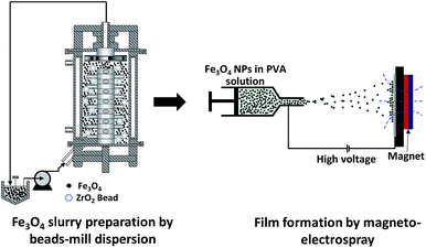
:![[thin space (1/6-em)]](https://www.rsc.org/images/entities/char_2009.gif) 3. The solution was loaded into a syringe pump (PhD 2000, Harvard Apparatus, USA), which was used to control the solution flow rate and set to a fixed rate of 20.0 μL min−1. The internal and external diameters of the needle used were 0.48 and 0.70 mm, respectively. An aluminum plate was placed facing the needle tip at a distance of 12 cm. Silicon wafers were attached to the plate and used as substrates to collect the samples sprayed out from the needle tip. Voltages of +6.0 and −6.0 kV were applied to the needle tip and the aluminum plate, respectively. An external magnetic field of 0.1 T was applied to the substrate, perpendicular to the collector, by a permanent magnet, in a similar arrangement to that described in our previous paper.14 For analysing the properties of the deposited film, samples are taken from the center part of the permanent magnet to minimize the magnetic field gradient. The experiment was conducted under controlled conditions of 30 ± 2 °C and a relative humidity of 35 ± 4%. The preparation route to the Fe3O4 nanoparticle films is illustrated in Fig. 1.
3. The solution was loaded into a syringe pump (PhD 2000, Harvard Apparatus, USA), which was used to control the solution flow rate and set to a fixed rate of 20.0 μL min−1. The internal and external diameters of the needle used were 0.48 and 0.70 mm, respectively. An aluminum plate was placed facing the needle tip at a distance of 12 cm. Silicon wafers were attached to the plate and used as substrates to collect the samples sprayed out from the needle tip. Voltages of +6.0 and −6.0 kV were applied to the needle tip and the aluminum plate, respectively. An external magnetic field of 0.1 T was applied to the substrate, perpendicular to the collector, by a permanent magnet, in a similar arrangement to that described in our previous paper.14 For analysing the properties of the deposited film, samples are taken from the center part of the permanent magnet to minimize the magnetic field gradient. The experiment was conducted under controlled conditions of 30 ± 2 °C and a relative humidity of 35 ± 4%. The preparation route to the Fe3O4 nanoparticle films is illustrated in Fig. 1.
2.4 Characterization
The morphologies of the Fe3O4 NPs and films were observed with a field emission scanning electron microscope (FE SEM; Hitachi S-5000, Japan) and a transmission electron microscope (TEM; JEM-3000F, JEOL, Japan). The crystalline structure of the NPs was examined by X-ray diffraction (XRD; D2 Phaser, Bruker, Germany). Their magnetic properties were evaluated on a superconducting quantum interference device (SQUID, Quantum Design, USA). Magnetization was measured as a function of applied field from 1 to 50 kOe at 300 K.3. Results and discussion
3.1 Dispersion of the Fe3O4 NPs
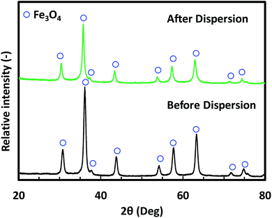
Fig. 2 shows the morphology of the Fe3O4 NPs before and after dispersion. The mean sizes of these NPs were 10, 25, and 45 nm in the Fig. 2(a, d), (b, e) and (c, f), respectively. The SEM images (Fig. 2(a–c)) show that the Fe3O4 NPs were agglomerated before dispersion. Owing to the agglomeration of the as-prepared Fe3O4 NPs, the dispersion step was required to break up agglomerates prior to nanoparticle film preparation. The morphology of the Fe3O4 NPs after dispersion is shown in Fig. 2(d–f). These TEM images show that after dispersion, non-agglomerated particles without any necking among the particles were obtained. The images also indicated that the morphology of NPs was unaffected by the dispersion process. The XRD patterns in Fig. 3 confirm that the crystal structure of the Fe3O4 NPs after the bead-mill dispersion did not change compared to that before bead-mill dispersion. The XRD patterns of the 10 and 45 nm NPs show the same result. Thus, the bead-mill dispersion process produced well-dispersed Fe3O4 NPs without affecting the structure of the particles, consistent with our previous studies.17–19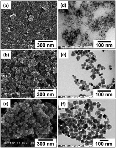 | ||
| Fig. 2 SEM and TEM images of Fe3O4 nanoparticles before (a–c) and after (d–f) bead-mill dispersion. Mean sizes of the nanoparticles were 10 (a and d), 25 (b and e), and 45 nm (c and f). | ||
Fig. 4 shows the hysteresis loops of the 10, 25, and 45 nm Fe3O4 NPs before and after dispersion. The saturation magnetization (Ms) of the Fe3O4 NPs was similar before (∼67.6 emu g−1) and after dispersion (∼67.1 emu g−1). Conversely, the Hc values of the dispersed single-domain Fe3O4 NPs were slightly lower than those before dispersion. The Hc values of the 25 and 45 nm Fe3O4 NPs before dispersion were 37.5, and 126.8 Oe, respectively. After dispersion, the Hc values decreased to 17.5 and 53.1 Oe, respectively. This decrease in Hc was caused by magnetic dipole coupling among the dispersed NPs. This result is consistent with previous reports on the dispersion of single-domain α′′-Fe16N2 NPs.19 The similarity suggests that the decrease of Hc after dispersion is a typical characteristic of single-domain magnetic NPs. During the SQUID measurement, when the magnetic field was removed, the well-dispersed NPs were able to move easily, allowing coupling of their magnetic moments. This coupling provided a demagnetization field, which led to a decrease in the Hc value. For the superparamagnetic NPs, the Hc value was close to zero and the dispersion process did not affect the Hc.
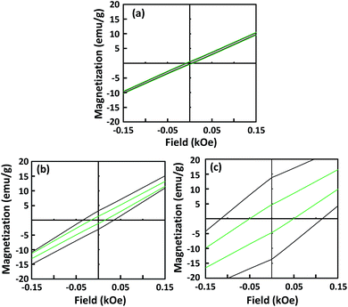 | ||
| Fig. 4 Hysteresis loops of 10 (a), 25 (b), and 45 nm (c) Fe3O4 nanoparticles. Black and green lines correspond to before and after dispersion, respectively. | ||
3.2 Fe3O4 nanoparticle deposited films
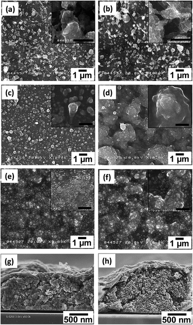
The well-dispersed Fe3O4 NPs were deposited on a Si-wafer by an electrospray method. Fig. 5 shows the surface morphologies of the deposited films prepared from the three sizes of Fe3O4 NPs, i.e., 10 nm (a, b); 25 nm (c, d); and 45 nm (e, f), from depositions without (a, c, e) and with (b, d, f) a magnetic field. Cross-sectional SEM images (g, h) show the films deposited from the 25 nm Fe3O4 NPs. The surface of the single-domain NPs (25 and 45 nm) showed a different morphology from that of the superparamagnetic NPs (10 nm). The films prepared under magnetic fields also showed a different surface morphology from the films deposited without a magnetic field. When the magnetic field was applied during the deposition, the film surface formed spike-like shapes. This pattern is generally observed in ferrofluids under a magnetic field.32 This phenomenon is consistent with a previous report of α′′-Fe16N2 NPs films prepared by spin-coating.13,15 The cross-sectional SEM images of films deposited under a magnetic field showed that the Fe3O4 NPs were dispersed inside the film.For the case of the nanoparticle film deposited from superparamagnetic NPs, the SEM images showed a forest-like morphology both in the presence and absence of an applied magnetic field. This different morphology might be attributed to the small particle size and their magnetic properties. The residual magnetism, i.e., the magnetic (Mr) remanence, value was zero for the superparamagnetic NPs and increased as the particle size of the single-domain NPs increased.33 Residual magnetic forces can increase aggregation of particles during the water evaporation process, which can in turn prevent droplet dispersion by electrostatic forces of the electrospray system. Additionally, the Fe3O4 nanoparticle size also limits the minimum size of the final droplet formed between leaving the needle tip and deposition on the substrate. The small Fe3O4 NPs enabled formation of small droplets, which deposited as films with a fine structure. According to previous analysis,30 higher conductivity of the droplet and substrate surface will also promote the formation of a forest-like structure.
XRD patterns of selected nanoparticle films composed of 25 nm Fe3O4 NPs featured typical Fe3O4 crystalline structures, as shown in Fig. 6. The 10 nm and 45 nm Fe3O4 films show similar XRD patterns. The XRD peaks of (111), (311), (222), and (400) from crystalline Fe3O4 were visible in the 2θ range of 25–60°. This pattern agreed with typical results of magnetite crystals.34 Thus, the prepared films retained the inherent crystalline properties of the NPs. The differences in the baseline of the XRD patterns likely originates from the PVA component in the film. Unlike a α′′-Fe16N2 nanoparticle film,15 alignment of the easy axis of the particles did not affect the intensity of their XRD spectrum. This result can be attributed to the weak magnetic field applied, and the relatively weak magnetic properties of the Fe3O4 NPs compared with those of α′′-Fe16N2 NPs.
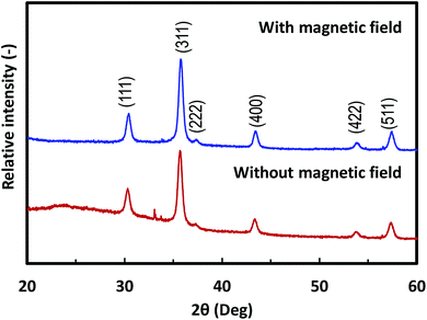 | ||
| Fig. 6 XRD patterns of magnetic films composed of 25 nm Fe3O4 nanoparticles deposited with and without a magnetic field. | ||
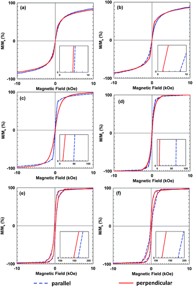
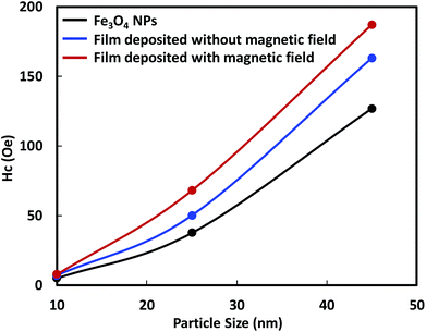
Fig. 7 shows hysteresis loops of films composed of three sizes of Fe3O4 NPs, deposited with and without the influence of the magnetic field. Compared with the Hc values of the precursor NPs, those of the deposited films increased and decreased when measured parallel and perpendicular to the film surfaces, respectively, as shown in Fig. 7(a), (c) and (e). This anisotropy resulted from stronger interactions among the magnetic NPs along the film surface direction than the interactions in the perpendicular direction. The difference of the Hc values was more pronounced when the magnetic field was applied, as shown in Fig. 7(b), (d) and (f). Additionally, the magnetic field generated by the permanent magnet was not uniformly distributed over the substrate surface and the field gradient along the surface direction was higher than that perpendicular to the surface. Owing to the magnetic NPs preference for moving along the field gradient, the number density distribution of the Fe3O4 NPs along the film surface could be enhanced by applying a non-uniform magnetic field.35 This result emphasizes the alignment of the magnetic moments of the NPs. The application of the magnetic field during the film deposition aligned the magnetic moments of the NPs, which increased the Hc and Mr values of the film. This result was consistent with those for α′′-Fe16N2 NPs.13–15
The smaller Hc value, which was measured perpendicular to the film surface emphasizes the alignment of the magnetic moment of the Fe3O4 NPs. Their magnetic moments aligned perpendicular to the film surface in the direction of the magnetic field. The Hc value of the films deposited from 10 nm Fe3O4 NPs was close to zero and did not increase as much as those of the single-domain NPs with larger diameters. The single-domain NPs showed a noticeable enhancement of their magnetic properties owing to the alignment of their magnetic moments. The relationship between the enhancement of the Hc value and the particle size, is illustrated in Fig. 8. This figure shows that the enhancement of the Hc value increased as the particle diameter increased. The Hc value of magnetic NPs is known to increase to a certain maximum value before decreasing to zero with decreasing particle size. Structuring of the particles to achieve the highest Hc value under the magnetic field is preferable for their application in magnetic films or bulk magnets. Single-domain NPs, which have a single magnetic moment show better structuring than multi-domain NPs. In addition, single domain NPs have stronger magnetic properties than multi-domain NPs.
Fig. 9 illustrates the phenomenon of the magnetic moment direction inside the film which is located on the center part of the permanent magnet. During the electrospray, the magnetic field produced a driving force that led to the formation of a smaller cone jet.14 The smaller cone jet further produced smaller droplets, which contained fewer Fe3O4 NPs. Under the applied magnetic field, the electric current can be used to control the cone-jet geometry to reduce the spinning jet instability.27 Therefore, the needle tip generated a uniform cone-jet resulting in uniform droplets. The magnetic moments of the Fe3O4 NPs inside the film aligned along the direction of the magnetic field.
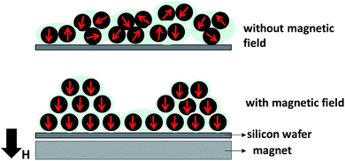 | ||
| Fig. 9 Illustration of the magnetic nanoparticle direction inside films deposited with and without a magnetic field. | ||
4. Conclusion
The preparation and evaluation of uniform aligned Fe3O4 nanoparticle films via magneto-electrospray is reported for the first time. A well-dispersed Fe3O4 NPs in water slurry was prepared by bead-mill dispersion. The Fe3O4 NPs slurry was then mixed with a PVA solution to prepare the film via electrospray under the influence of a 0.1 T magnetic field. The dispersion process successfully broke-up agglomerated Fe3O4 NPs into their primary sizes without affecting their shape or structure. XRD results confirmed that the deposition process did not change the crystalline structure of the Fe3O4 NPs. Although the Hc values of the Fe3O4 nanoparticle slurries decreased, the values were enhanced in their films after deposition. We obtained further enhancement of the Hc values via the application of a magnetic field during the film deposition. This enhancement of the Hc value increased as the diameter of the constituent NPs increased. These results indicate that electrospray deposition methods with an applied magnetic field has good potential for structuring magnetic NPs with controllable magnetic properties.Conflicts of interest
There are no conflicts to declare.Acknowledgements
We gratefully acknowledge the Ministry of Education, Culture, Sports, Science, and Technology (MEXT) of Japan for providing Scholarships (C.·W.·K.). This work was also supported by JSPS KAKENHI Grant Number 26709061 and 16K13642. This work is partly supported by the Center for Functional Nano Oxide at Hiroshima University. The authors thank Professor Toshiro Takabatake and Associate Professor Takahiro Onimaru from the Department of Quantum Matter, Graduate School of Advanced Sciences of Matter, Hiroshima University, for SQUID measurements and Dr Makoto Maeda from the Natural Science Center for Basic Research and Development (NBARD), Hiroshima University, for TEM analysis.Notes and references
- F. Wortmann and K. Flüchter, Business & Information Systems Engineering, 2015, 57, 221–224 Search PubMed.
- T. A. P. Rocha-Santos, TrAC, Trends Anal. Chem., 2014, 62, 28–36 CrossRef CAS.
- N. Liakakos, T. Blon, C. Achkar, V. Vilar, B. Cormary, R. P. Tan, O. Benamara, G. Chaboussant, F. Ott, B. Warot-Fonrose, E. Snoeck, B. Chaudret, K. Soulantica and M. Respaud, Nano Lett., 2014, 14, 3481–3486 CrossRef CAS PubMed.
- C. Chappert, A. Fert and F. N. Van Dau, Nat. Mater., 2007, 6, 813–823 CrossRef CAS PubMed.
- Y. V. Kolen’ko, M. Bañobre-López, C. Rodríguez-Abreu, E. Carbó-Argibay, A. Sailsman, Y. Piñeiro-Redondo, M. F. Cerqueira, D. Y. Petrovykh, K. Kovnir, O. I. Lebedev and J. Rivas, J. Phys. Chem. C, 2014, 118, 8691–8701 Search PubMed.
- K. Yoo, B. G. Jeon, S. H. Chun, D. R. Patil, Y. J. Lim, S. H. Noh, J. Gil, J. Cheon and K. H. Kim, Nano Lett., 2016, 16, 7408–7413 CrossRef CAS PubMed.
- E. D. Daniel and I. Levine, J. Acoust. Soc. Am., 1960, 32, 1 CrossRef.
- J. P. Hong, S. B. Lee, Y. W. Jung, J. H. Lee, K. S. Yoon, K. W. Kim, C. O. Kim, C. H. Lee and M. H. Jung, Appl. Phys. Lett., 2003, 83, 1590–1592 CrossRef CAS.
- T. Yamada, K. Morita, K. Kume, H. Yoshikawa and K. Awaga, J. Mater. Chem. C, 2014, 2, 5183 RSC.
- D. Ling and T. Hyeon, Small, 2013, 9, 1450–1466 CrossRef CAS PubMed.
- M. S. Lin and H. J. Leu, Electroanalysis, 2005, 17, 2068–2073 CrossRef CAS.
- C. T. Yavuz, J. T. Mayo, W. W. Yu, A. Prakash, J. C. Falkner, S. Yean, L. Cong, H. J. Shipley, A. Kan, M. Tomson, D. Natelson and V. L. Colvin, Science, 2006, 314, 964–967 CrossRef PubMed.
- A. Suhendi, C. W. Kartikowati, R. Zulhijah, T. Ogi, T. Iwaki and K. Okuyama, Adv. Powder Technol., 2015, 26, 1618–1623 CrossRef CAS.
- C. W. Kartikowati, A. Suhendi, R. Zulhijah, T. Ogi, T. Iwaki and K. Okuyama, Nanotechnology, 2016, 27, 025601 CrossRef PubMed.
- C. W. Kartikowati, A. Suhendi, R. Zulhijah, T. Ogi, T. Iwaki and K. Okuyama, Nanoscale, 2016, 8, 2648–2655 RSC.
- T. Ogi, A. B. D. Nandiyanto and K. Okuyama, Adv. Powder Technol., 2014, 25, 3–17 CrossRef CAS.
- T. Ogi, R. Zulhijah, T. Iwaki and K. Okuyama, KONA Powder Part. J., 2017, 34, 3–23 CrossRef.
- T. Tahara, Y. Imajyo, A. B. D. Nandiyanto, T. Ogi, T. Iwaki and K. Okuyama, Adv. Powder Technol., 2014, 25, 1492–1499 CrossRef CAS.
- R. Zulhijah, A. Suhendi, K. Yoshimi, C. W. Kartikowati, T. Ogi, T. Iwaki and K. Okuyama, Langmuir, 2015, 31, 6011–6019 CrossRef CAS PubMed.
- S. Gálvez, J. Rubio-Zuazo, E. Salas-Colera, A. Muñoz-Noval and G. R. Castro, Appl. Phys. Lett., 2014, 105, 241603 CrossRef.
- X. Guan, G. Zhou, W. Xue, Z. Quan and X. Xu, APL Mater., 2016, 4, 036104 CrossRef.
- P. Prieto, J. de la Figuera, L. Martín-García, J. E. Prieto and J. F. Marco, J. Mater. Chem. C, 2016, 4, 7632–7639 RSC.
- C. Zhao, Y. Ma, C. Shen and W. Han, J. Nanosci. Nanotechnol., 2016, 16, 950–955 CrossRef CAS PubMed.
- M. Monti, M. Sanz, M. Oujja, E. Rebollar, M. Castillejo, F. J. Pedrosa, A. Bollero, J. Camarero, J. L. F. Cuñado, N. M. Nemes, F. J. Mompean, M. Garcia-Hernández, S. Nie, K. F. McCarty, A. T. N'Diaye, G. Chen, A. K. Schmid, J. F. Marco and J. de la Figuera, J. Appl. Phys., 2013, 114, 223902 CrossRef.
- R. Takahashi, H. Misumi and M. Lippmaa, Cryst. Growth Des., 2012, 12, 2679–2683 CAS.
- H. M. Lee, S. G. Kim, I. Matsui, T. Iwaki, F. Iskandar, I. W. Lenggoro and K. Okuyama, J. Magn. Magn. Mater., 2007, 313, 62–68 CrossRef CAS.
- A. Suhendi, M. M. Munir, A. B. Suryamas, A. B. D. Nandiyanto, T. Ogi and K. Okuyama, Adv. Powder Technol., 2013, 24, 532–536 CrossRef CAS.
- A. Suhendi, A. B. Nandiyanto, M. M. Munir, T. Ogi, L. Gradon and K. Okuyama, Langmuir, 2013, 29, 13152–13161 CrossRef CAS PubMed.
- A. Suhendi, A. B. D. Nandiyanto, M. M. Munir, T. Ogi and K. Okuyama, Mater. Lett., 2013, 106, 432–435 CrossRef CAS.
- Q. Li, C. W. Kartikowati, T. Ogi, T. Iwaki and K. Okuyama, Carbon, 2017, 115, 116–119 CrossRef CAS.
- N. Uchida, K. Fujioka, K. Aoki, H. Misawa and M. Kozawa, Magnetic particles for magentic toner and process for producing the same, Toda Kogyo Corporation, US Pat., 5843610, 1998.
- N. A. Clark, Nature, 2013, 504, 229–230 CrossRef CAS PubMed.
- D. Kim, N. Lee, M. Park, B. H. Kim, K. An and T. Hyeon, J. Am. Chem. Soc., 2009, 131, 454–455 CrossRef CAS PubMed.
- S. Sun and H. Zeng, J. Am. Chem. Soc., 2002, 124, 8204–8205 CrossRef CAS PubMed.
- G. Sreenivasulu, M. Popov, R. Zhang, K. Sharma, C. Janes, A. Mukundan and G. Srinivasan, Appl. Phys. Lett., 2014, 104, 052910 CrossRef.
| This journal is © The Royal Society of Chemistry 2017 |

