 Open Access Article
Creative Commons Attribution 3.0 Unported Licence
Dynamic/quasi-static stab-resistance and mechanical properties of soft body armour composites constructed from Kevlar fabrics and shear thickening fluids†
Jianbin Qin ,
Guangcheng Zhang*,
Lisheng Zhou
 ,
Jiantong Li and
Xuetao Shi*
Key Laboratory of Space Applied Physics and Chemistry, Ministry of Education, School of Natural and Applied Sciences, Northwestern Polytechnical University, Xi'an 710072, China. E-mail: zhangguc@nwpu.edu.cn; shixuetao@nwpu.edu.cn
First published on 15th August 2017
Abstract
Soft body armour composites were constructed by combining Kevlar fabrics with different quantities of shear thickening fluid (STF). In particular, the quantity of the added STF and the mechanical properties of these composites were systemically explored. The dynamic and quasi-static knife-stabbing resistance and the quasi-static mechanical properties of these composites were both significantly enhanced in comparison to those of neat Kevlar fabric. The composites were much lighter, thinner and more flexible than the neat Kevlar fabric and, with an optimal quantity of added STF, could not even be penetrated. However, the dynamic knife-stabbing resistance of the fabric became poor when the amount of added STF was higher than 100 wt%. The tensile strength of the composites could be increased from 40% to 80% and the tearing strength could be increased by nearly eight times that of the neat Kevlar fabric by increasing the concentration of added STF. Yarn pull-out testing suggested that the triggered shear thickening contributed to the increase of the friction between yarns or filaments, resulting in improvements in the dynamic and quasi-static properties of these composites. Moreover, these composites are suitable for use as soft body armour materials due to their good adaptability to high and low speeds conditions.
1. Introduction
Shear-thickening fluid (STF) is a novel suspension whose viscosity can increase with increasing shear rate or applied stress. Under a high-speed shear rate, the viscosity of the STF increases dramatically, and it appears as a solid-like material. Moreover, the STF immediately reverses its state to a liquid-like material when the impact stress is removed.1–5 In other words, STFs are self-adjusting smart materials.Hoffman has proposed that shear thickening in concentrated suspensions results from the order–disorder transition.6,7 Other researchers have demonstrated that the shear-thickening behavior in concentrated colloidal suspensions is caused by hydrodynamic lubrication forces between particles, resulting in the formation of a non-equilibrium, self-organized microstructure that develops under strong flows, denoted as hydroclusters.8–12 Recently, jamming and dilation for shear thickening in dense dispersions have been described.13–17 The idea is that the particle system in suspension dilates, i.e., particles tend to expand when they are made to flow.
Shear thickening behavior is not desirable in some industries, such as food, paint and ceramics, where it leads to issues such as failure of mixer motors due to overloading and mixer blade damage in industrial situations.1,18 However, STFs have attracted much attention, and they have been used in the design of protective smart composites over the past few decades.19–30
Decker et al. performed systematic research on the stab resistance of STF-treated fabrics for the first time in 2006.22 They concluded that the stab resistances of STF-treated Kevlar and nylon fabrics were improved significantly over those of the neat fabric targets; dramatic improvements in puncture resistance were observed, while slight increases in knife protection were also observed. Decker et al. also proposed that the added STF reduced the mobility of filaments and yarns, which led to the improvements in stab resistance. The added weight percentage of STF was between 20 and 30 for all STF-treated fabrics in this study.22 Li et al. demonstrated that the dynamic stab resistance of UHMWPE fabric was significantly enhanced by the presence of an STF. They proposed that the impregnating STF accelerated the transverse response of the UHMWPE fabric and increased the inter-yarn friction. The role of the STF in the STF-treated fabrics was important; however, the quantity of the impregnated STF in the fabrics was ignored in this study.31 Selim and Melih found that multi-phase STFs resulted in further improvements in the stab resistance of STF-treated fabrics with respect to single-phase STFs. They also proposed that the STF in the STF-treated fabrics increased the inter-yarn friction and led to improvements in stab resistance. The weight percentage of the added STF was only 10 for all STF-treated fabrics in this study.32 Feng et al. investigated the quasi-static stab resistance of STF-treated aramid fabrics and found that the aramid fabrics exhibited significant enhancements in quasi-static stab resistance after treatment with STF.29 They also proposed that the enhancement in quasi-static stab resistance was due to increased friction between the yarns and filaments impregnated with STF. However, the quantity of absorbed STF in the aramid fabrics was not mentioned in this study.29 Kang et al. reported that STF impregnation significantly improved the stab resistance of Kevlar fabric against spike threats. The role of the STF in the STF-treated fabrics was not mentioned, and the quantity of the absorbed STF in the fabrics was also ignored in this study.33 Kalman et al. reported that stab resistance and ballistic resistance were enhanced for STF–Kevlar composites that absorbed 9 wt% to 14 wt% STF.23,34 Majumdar found that the silica concentration, padding pressure and square of solvent ratio were the statistically significant terms influencing the impact energy absorption. The added STF in their composites was not more than 7 wt%.26–28
In summary, the role of STFs has been demonstrated and accepted in most studies, i.e., the STF increases the friction between yarns and filaments and constrains the mobility of yarns and filaments in STF-treated fabrics. In this case, more yarns and filaments simultaneously sustain knife or spike threats instantaneously and impede their penetration. The friction between yarns and filaments should be related to the quantity of the absorbed STF between them; however, as stated above, all reports to date have ignored the relationship between the friction and the quantity of absorbed STF. The quantity of absorbed STF in STF-treated fabrics is no greater than 30 weight% and is usually a constant value in most existing reports. Moreover, the calculated volume porosity of Kevlar fabrics is between 40% and 70%, as stated in ref. 35. The density of the STF is much greater than that of the Kevlar fiber; hence, the theoretical quantity of absorbed STF in STF-treated fabrics is not less than 100 weight%. In other words, the quantity of absorbed STF in STF-treated fabrics is too low in most existing reports. In addition, the friction between yarns and filaments in STF-treated fabrics may be increased by increasing the quantity of absorbed STF, which may be favorable for improvements in stab resistance. Thus, it is significant to investigate STF-treated fabrics containing high quantities of STF.
In addition, STF-treated Kevlar fabrics as soft body armour materials will mostly experience quasi-static forces and rarely experience dynamic knife stab threats. Therefore, quasi-static properties, including tensile and tearing strength, are very important for STF-treated Kevlar fabrics in service life; moreover, related studies have not been reported, and it is necessary to investigate these properties.
In this study, a dispersion medium with low molecular weight, polyethylene glycol, was selected to prepare STF with silica microspheres. Both the dynamic and quasi-static knife-stabbing resistance and the quasi-static mechanical properties of the STF-treated Kevlar fabric composites with much greater quantities of added STF were investigated systemically for the first time. Moreover, yarn pull-out and tensile tests were performed to explore the inner mechanisms of the various STF-treated Kevlar fabrics, and bending length tests were performed to study their flexural rigidity. The detailed mechanisms of the STFs in the Kevlar fabrics were explored by combining the results of the dynamic and quasi-static tests.
2. Materials and methods
2.1 Materials
Tetraethoxysilane, absolute ethyl alcohol, polyethylene glycol with a molecular weight of 400 g mol−1 (PEG-400) and aqueous ammonia (weight% 28) were purchased from the Sinopharm Chemical Reagent Co., Ltd. Ultrapure water was used for all experiments. Plain woven Kevlar fabrics with K-29 were supplied by the Dupont Company; the area density was 240 g m−2. Monodisperse silica microspheres with a diameter of 500 nm were prepared by a sol–gel method, and the products were centrifuged and washed with absolute ethyl alcohol at least three times.2.2 Preparation of STFs
Silica microspheres were dried at 100 °C for 12 h to remove water and then dispersed in PEG-400 by ultrasonication for not less than 2 h. The obtained samples were dried under vacuum at 80 °C for 24 h. Five STFs with different concentrations, 55 wt%, 60 wt%, 65 wt%, 68 wt% and 70 wt%, were prepared.2.3 Preparation of composite and PEG-treated Kevlar fabrics
Various diluted STFs were obtained by adding 300 ml, 250 ml, 200 ml or 150 ml ethyl alcohol to different beakers containing 100 g STF. Then, different groups of neat Kevlar fabric were impregnated in the diluted STFs for 30 min. The impregnated fabrics were dried at 60 °C for 24 h and then dried in a vacuum oven at 80 °C for no less than 24 h to eliminate ethyl alcohol and water. The amount of added STF or PEG-400 was calculated by eqn (1). Four groups of composites with 13.4 wt%, 36.23 wt%, 65.21 wt% and 103.79 wt% added STF were prepared. The PEG-treated fabrics were prepared by impregnating Kevlar fabrics in PEG-400; then, surplus PEG-400 was removed with a pressure of about 2 bar. All samples were sealed with membranes.
 | (1) |
2.4 Measurements
All rheological experiments were performed with a stress controlled rheometer (Anton Paar MCR 302) at 30 °C. According to the principles of NIJ Standard-0115.00, the dynamic knife-stabbing tests were performed with a simple self-made installation, as shown in Fig. 1a. Fig. 1b and c show the installation of the target and the target holder. The drop mass contained a cylinder steel and the knife; the total mass was about 4500 g. The air drag on the drop mass was ignored, and the impacting energy was calculated by eqn (2). The conditions of the dynamic knife-stabbing tests are shown in Table 1.| Impacting energy = m × g × h | (2) |
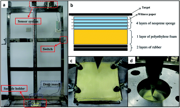 | ||
| Fig. 1 (a) Measuring installation, (b) installation of target and (c) target holder for the dynamic knife-stabbing tests, and (d) sample holder for the quasi-static knife-stabbing tests. | ||
| Drop mass (kg) | Drop height (cm) | Theoretical impact velocity (m s−1) | Theoretical impact energy (J) |
|---|---|---|---|
| 4.50 | 10 | 1.96 | 4.41 |
| 15 | 2.94 | 6.62 | |
| 20 | 3.92 | 8.82 | |
| 25 | 4.90 | 11.03 | |
| 30 | 5.88 | 13.23 |
The quasi-static knife-stabbing tests were performed with the electronic universal testing machine; the sample was clamped by a self-designed cylindrical holder, as shown in Fig. 1d. Sufficient force was introduced to clamp the specimen with the bolts in order to avoid slippage. The instrument measured the generated force, and the absorbed energy was simultaneously calculated for the sample against the displacement.
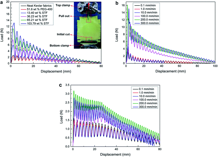
The quasi-static mechanical properties, tensile strength and tearing strength in warp direction, were measured with the electronic universal testing machine, referencing ASTM D5034 and ASTM D2261, respectively. The single yarn pull-out tests were performed as follows: the bottom portion of single yarn at the center of each specimen was intentionally cut so that it could be pulled out without elastic deformation or failure. The top of that yarn was loaded into the upper clamp of the testing machine, while the lower edge of the rectangular fabric specimen was mounted in a clamped holding fixture, as shown in the inset of Fig. 10a. Referencing ASTM D2256, the tensile strength of the single yarn was tested with the electronic universal testing machine. The flexural rigidities of the samples were measured with electronic rigidity equipment (LLY-01B) as stated in option A (cantilever test) of ASTM D1388.
3. Results and discussion
3.1 Properties of STFs
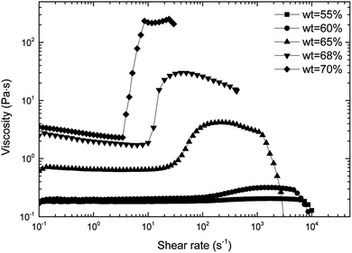
As shown in Fig. 2, STFs with different concentrations exhibit shear thickening behavior. With increasing concentration of STF, corresponding to the onset increase of viscosity, the critical shear rate decreases. For the STF with 70 wt% silica microspheres, the viscosity increases by nearly two orders of magnitude in the shear thickening region, and it presents jamming at high shear rates. The 70 wt% STF displayed such prominent shear thickening properties that it was selected to be combined with Kevlar fabrics. Moreover, the STF showed complete reversibility and instantaneous response (as shown in Fig. S1 and S2 in the ESI†). This indicates that the STF can be used repeatedly and responds quickly to external conditions.3.2 Dynamic and quasi-static knife-stabbing resistance
As shown in Table 2 and Fig. 3, the targets of neat and PEG-treated Kevlar fabrics are composed of twelve layers, while the targets of STF-prepared composites are constructed of nine layers. Although the targets of the composites were thinner than the other targets, their stabbing penetration was less than those of the neat and PEG-treated Kevlar fabrics. Both the untreated and PEG-treated targets with twelve layers were penetrated easily. Moreover, the areal density of the target with 13.40 wt% added STF was lower than that of the neat Kevlar fabric target, while its stabbing penetration was also lower. The knife-stabbing resistances of the targets for the composites containing 36.23 wt% and 65.21 wt% STF are prominent. The knife could not penetrate the target and was bounced back in some dynamic knife-stabbing tests. However, the knife-stabbing resistance became low and the area density was very high for the target containing excessive STF (103.79 wt% added). It is clear that the optimal amount of added STF is between 36.23 wt% and 65.21 wt% for dynamic stab resistance.| Label | Dimensions: length (cm) by width (cm) | STF absorbing capacity (wt%) | PEG-400 absorbing capacity (wt%) | Number of layers in target | Areal density (g m−2) |
|---|---|---|---|---|---|
| Neat Kevlar fabric | 15 × 15 | 0.00 | 0.00 | 12 | 2880 |
| PEG-400/Kevlar fabric | 15 × 15 | 0.00 | 51.60 | 12 | 4366 |
| STF/Kevlar fabrics | 15 × 15 | 13.40 | 4.02 | 9 | 2449 |
| 15 × 15 | 36.23 | 5.28 | 9 | 2942 | |
| 15 × 15 | 65.21 | 9.51 | 9 | 3568 | |
| 15 × 15 | 103.79 | 15.13 | 9 | 4401 |
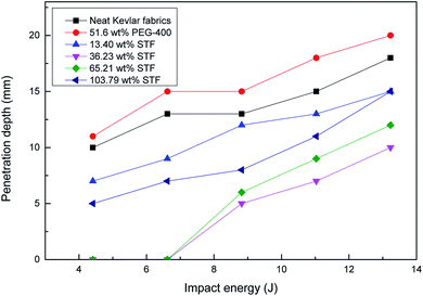 | ||
| Fig. 3 Impact energy dependencies of the knife penetration depth for targets containing different quantities of STF and 51.6 wt% PEG. | ||
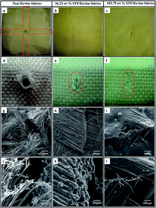
Furthermore, to investigate the microscopic mechanism, microscopic pictures of the damaged targets were investigated by photographic and SEM images, as shown in Fig. 4. For the neat Kevlar fabric, a crossed trace arises for the slippage of yarns around the cutting hole, as shown in the red rectangle in Fig. 4a. The broken cross-section is irregular, and the filaments are frayed and disordered, as shown in Fig. 4d and g. Some fibrils are dragged out, as shown in Fig. 4j. For the STF-prepared composites, as shown in Fig. 4b and c, the crossed trace does not exist around the cutting hole, implying that the friction in the yarns is increased. The damaged cross-section of yarns is more regular than that of the neat Kevlar fabric, as shown in Fig. 4e, f, h, i, k and l; this indicates that the mobility of the yarns declines, which can be attributed to the increase of friction between yarns. Moreover, it is clear that the STF is coated perfectly on the filaments in the composites, as shown in Fig. 4k. There is a large quantity of surplus STF on the surface of the target with 103.79 wt% STF, and its cutting hole is significantly larger than that of the target with 36.23 wt% STF.
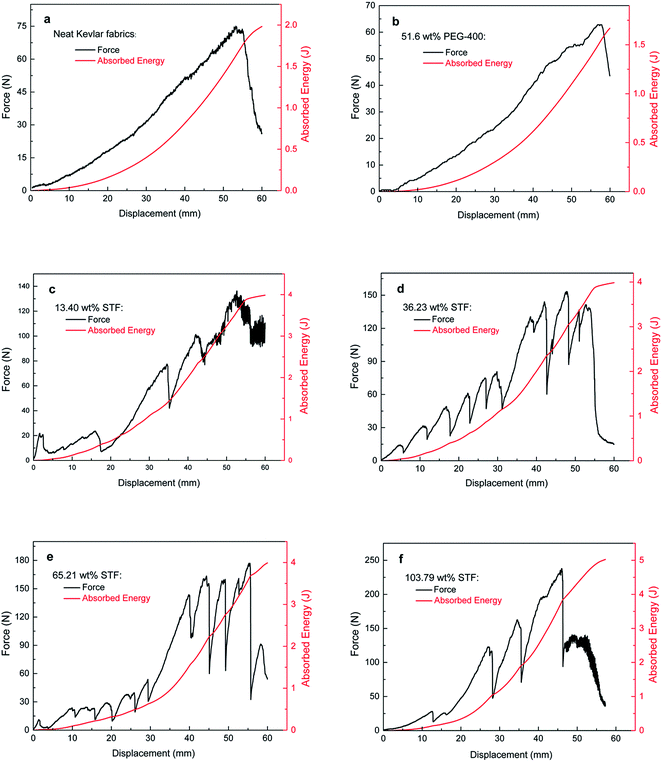
Fig. 5 presents the generated force and absorbed energy against displacement as the knife quasi-statically punctured the neat Kevlar fabric, PEG-treated fabric and STF-prepared composites. Both the maximum generated force and the maximum absorbed energy in the composites are two or three times that of the neat or PEG-treated Kevlar fabrics, respectively. The maximum generated force in the neat or PEG-treated Kevlar fabrics was obtained at a displacement of about 55 mm, as shown in Fig. 5a and b, while the generated force in the composites reached a higher value at a relatively small displacement, as shown in Fig. 5c–f. Moreover, except for a few yarns or filaments, most of these slipped around the punctured hole in the neat or PEG-treated Kevlar fabrics (as shown in Fig. S3a in the ESI†), and the generated force increased steadily with increasing puncture displacement, as shown in Fig. 5a and b. However, the primary yarns are cut off one by one around the punctured hole in the composites (as shown in Fig. S3b in the ESI†); this may cause the generated force to ascend oscillatorily, as shown in Fig. 5c–f. This implies that the friction between yarns or filaments increases significantly with the introduction of STF, and the mobility of yarns or filaments in the composites is much weaker than that of the neat or PEG-treated Kevlar fabrics. The immobile yarns resist knife puncture until they are cut off one by one in the composites, and the cutting-off force of the yarn is much higher than the force that causes it to slip; therefore, the generated force is very high and oscillatory, and the absorbed energy increases evidently. With increasing quantity of added STF, the friction between yarns may increase, causing the resistance and the absorbed energy to increase. The friction between yarns declines upon the introduction of PEG-400, which lubricates the yarns in the Kevlar fabrics; therefore, the generated force and absorbed energy decrease. In other words, it is the STF that causes the increases in the generated force and the absorbed energy.
3.3 Quasi-static mechanical properties of STF-prepared Kevlar fabric composites
In the quasi-static tensile tests, compared with the neat Kevlar fabric, as the load increased steeply, the tensile strength increased significantly and the elongation at break decreased for the STF-prepared Kevlar fabric composites, as shown in Fig. 6a. Apparently, the yarns are crimped in the neat Kevlar fabrics and the STF-prepared composites at the initial state and are progressively straightened along the loading direction.33 The straightened length is similar for the same size samples of the neat Kevlar fabric and the composites. Therefore, the displacement, corresponding to the loading peak in the composites, is the same as that in the neat Kevlar fabric. The friction between yarns in the composites is higher than that in the neat Kevlar fabric, leading to an increase in the straightened resistance. Most yarns in the composites were broken after the loading peak was reached (as shown in Fig. S4b in the ESI†), and the tensile load declined steeply thereafter. However, most of the yarns or filaments slip readily in the neat Kevlar fabric after the loading peak value is obtained (as shown in Fig. S4a in the ESI†); therefore, its elongation at break is higher than that of the composite. It is clear that the tensile strengths of the composites are higher than those of the neat and PEG-treated Kevlar fabrics by 40% to 80%, as shown in Fig. 6b. By increasing the quantity of the added STF, the friction between yarns or filaments may increase; therefore, the tensile strength of the composites is improved. This suggests that the introduction of STF increases the quasi-static tensile strength of the Kevlar fabric.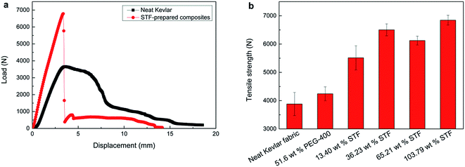 | ||
| Fig. 6 (a) Tensile load versus displacement and (b) tensile strength for Kevlar fabrics treated by different methods at a constant rate of 100 mm min−1. | ||
The results of the quasi-static tearing tests are shown in Fig. 7. It can be clearly seen that the tearing strengths of the neat and PEG-treated Kevlar fabrics are about 120 N and 70 N, respectively, and their absorbed energies are about 4.5 J and 2.1 J, respectively, as shown in Fig. 7a and b. However, both the tearing strength and the absorbed energy increase significantly for the STF-prepared composites; the tearing strength increases from about 400 N to 800 N and the absorbed energy increases from about 12 J to 30 J with increasing amount of added STF, as shown in Fig. 7c–f. Most of the yarns and filaments slip out in the tearing tests for high tensile strength of the Kevlar filament.34 This implies that the introduction of STF causes the friction between yarns to increase. For the neat and PEG-treated Kevlar fabrics, the tearing force increases progressively, and all yarns finally slip out. The tearing strength of the PEG-treated fabric is slightly lower than that of the neat Kevlar fabric because the inter-yarn friction decreases due to the lubrication of PEG-400. For the STF-prepared composites, the tearing force increases steeply at the initial displacements for the de-crimp and slippage of yarns. Some yarns are squeezed together at the point of the tearing gap with increasing displacement, which severely increases the friction between yarns; therefore, the tearing force is enhanced significantly. Moreover, the tearing force increases with increasing STF, also indicating that the friction between yarns or filaments is enhanced due to the introduction of the STF. The friction oscillates as soon as the yarns slip from one displacement to another, as shown in Fig. 7c–f; therefore, the tearing force is oscillatory. The tearing force decreases and its amplitude declines as the yarn progressively slips out of the fabrics.
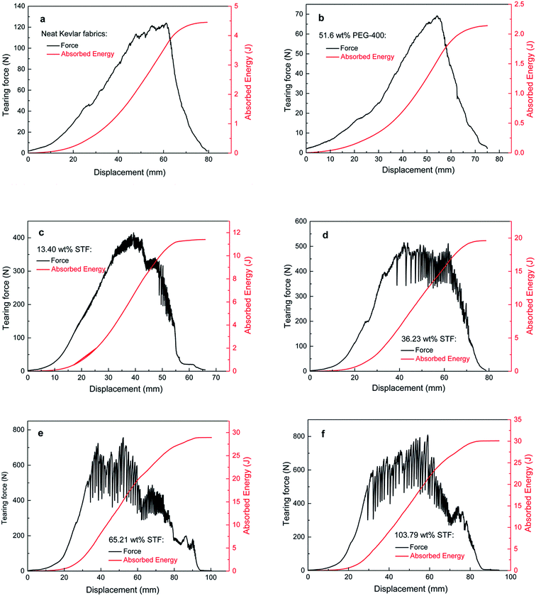 | ||
| Fig. 7 Tearing strength and energy absorption vs. displacement at a rate of 100 mm min−1 for (a) the neat Kevlar fabric, (b) the PEG-treated Kevlar fabric, and (c–f) the STF-prepared composites. | ||
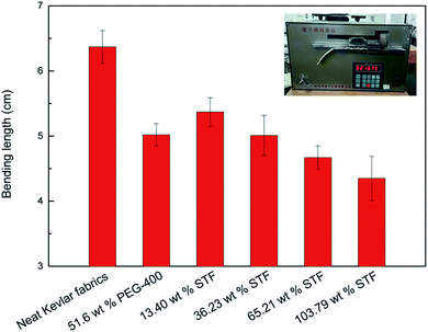
Moreover, compared with the neat Kevlar yarn, the tensile strengths of a single yarn for the composites with different amounts of added STF and the PEG-treated fabric are increased by about 12%, as shown in Fig. 8. The friction between the filaments in the yarns may also be enhanced due to the introduction of the STF, which is beneficial for the delivery of stress between different filaments. More filaments uniformly load the tensile stress, leading to increases in the tensile strengths of single yarns of the composites. Furthermore, the bending lengths of the composites and PEG-treated Kevlar fabric are shorter than that of the neat Kevlar fabric and decrease with increasing amount of added STF, as shown in Fig. 9. In other words, the flexural rigidity of the composites is better than that of the neat Kevlar fabric. Finally, the STF can be diluted and separated easily from the composites with ethyl alcohol and then recycled by volatilizing the ethyl alcohol.
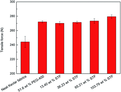 | ||
| Fig. 8 Tensile strengths of single yarns of Kevlar fabrics treated by different methods at a constant rate of 100 mm min−1. | ||
3.4 Mechanism of STF in Kevlar fabric composites
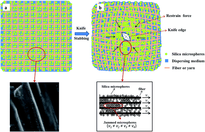
In order to demonstrate the working mechanism of the STF in fabrics, the effect of the STF on the friction in yarns was investigated in detail by single yarn pull-out tests, as shown in Fig. 10. In the first stage, the pull-out load increases rapidly, reaching the maximum value as soon as the straightening of the yarn has progressed past the final bottom transverse yarn. In the second stage, the pull-out force exhibits a fluctuant state as the residual crimp in the yarn moves alternately over and under transverse yarns. Moreover, it declines monotonically overall as the residual crimp and the length of the yarn in the fabric decreases progressively and engages with increasingly fewer transverse yarns. As shown in Fig. 10a, the pull-out forces of the different composites are much higher than those of the neat and PEG-treated Kevlar fabrics and increase with increasing amount of added STF. In contrast, the yarn pull-out force in the PEG-treated fabric is small and slightly less than that of the neat fabric due to the lubrication of PEG. In other words, the friction between yarns is significantly enhanced by the introduction of STF. As shown in Fig. 10b, the pull-out force of the composites with 65.21 wt% STF is small and similar to that in the neat fabric at lower testing rates, such as 0.1 mm min−1, 1 mm min−1 and 10 mm min−1. It increases prominently when the rate reaches 100 mm min−1, which is the same as the rates the of tensile and tearing tests. Moreover, with increasing rate of the pull-out tests, for 200 mm min−1 and 300 mm min−1, the yarn pull-out force increases slightly. However, the pull-out force changes slightly as the pull-out rate changes from low to high values for the neat Kevlar fabric, as shown in Fig. 10c. These results clearly demonstrate that the shear thickening of the STF between yarns is triggered as the relative rate of yarns exceeds 100 mm min−1 and the friction between yarns is enhanced.The working mechanism of STF in the composites can be explained as follows. At first, the STF combines uniformly with the Kevlar fabric, as shown in Fig. 11a. The gap (y) between adjacent filaments can be assumed to be 10 μm, which is larger than the practical value, as shown in Fig. 4k and l. The critical shear rate (γ) is about 4 s−1 for the 70 wt% STF, as shown in Fig. 2. The minimum critical velocity (v), estimated by the equation  , is only about 2.4 mm min−1. In other words, the shear thickening behavior can be triggered easily as soon as the yarns or filaments experience a relative motion under the knife impact, as shown in the inset of Fig. 11b. The distributed STF in the fabric acts as a bridging or matrix phase due to the very high viscosity of STF, and some silica microspheres may be jammed in the gaps between filaments, as shown in the inset of Fig. 11b. This causes stress to transfer between yarns or filaments, and more yarns or filaments function as an element to sustain the external dynamic or quasi-static impact, as shown in Fig. 11b. Thus, more energy can be absorbed and the composites can endure much higher forces during dynamic or quasi-static knife impact. In the quasi-static mechanical tests, the testing rate, 100 mm min−1, is much higher than the critical velocity; therefore, the shear thickening behavior of the STF can be triggered easily. This causes a prominent increase in the friction between yarns or filaments in the composites, and both the tensile strength and the tearing strength are enhanced. The tearing forces fluctuate in the composites, and the fluctuated amplitude increases with increasing amount of added STF. One possible reason is that the coupling between yarns or filaments will be destroyed when the external force is sufficiently strong; therefore, the tearing force declines sharply. However, new couplings will form quickly due to the reversible and transient response ability of STF, leading to a sharp increase in the tearing force. Moreover, the enhanced quasi-static mechanical properties, including the tensile strength and tearing strength, may also lead to improvements in the dynamic knife-stabbing resistance.
The dynamic knife-stabbing resistance decreases for composites containing an excessive quantity of STFs. One possible explanation is that the impacting behavior may not be optimized at the maximum friction but at some intermediate, tuned degree of mobility. Therefore, the yarns in the composites may be free to move to a certain extent, absorbing energy, lengthening the interaction time with the knife under impact, and decreasing the severity of the instantaneous stresses on the yarns and filaments. In this scenario, the very high pull-out force of the composites is detrimental to the overall stabbing performance, while enough slippage is permitted to reduce instantaneous stress concentrations in the vicinity of the impact. This example underscores an important conclusion that increased friction between yarns or filaments is not always beneficial. It is more likely that an optimal amount of added STF exists for these composites to resist knife impacts.
4. Conclusions
Both the dynamic and quasi-static knife-stabbing resistance and the quasi-static mechanical properties of STF-prepared Kevlar fabric composites are significantly improved compared to those of neat Kevlar fabric. The optimal dynamic knife-stabbing resistance is obtained when the added STF is between 36.23 wt% and 65.21 wt%. In this case, the composites are much lighter, thinner and more flexible than the neat Kevlar fabric and cannot even be penetrated by a knife. However, the dynamic stab resistance declines when the fabric contains excessive amounts of STF. The generated forces and the absorbed energies of the composites are much higher than that of the neat Kevlar fabric in the quasi-static knife-stab, and they increase with increasing amount of added STF. The quasi-static mechanical properties of STF-treated Kevlar fabric composites were studied for the first time. Both their tensile strengths and tearing strengths were enhanced significantly compared with those of neat Kevlar fabric. Their tensile strength is increased by 40% to 80%, and their tearing strength is increased by as much as nearly eight times as the amount of added STF increases. Moreover, the flexural rigidities of the composites were superior to that of the neat Kevlar fabric.The critical velocity of the shear thickening for STF in the composites is very low, and a series of yarn pull-out tests suggests that the increased friction between yarns or filaments is attributed to the shear thickening of the STF. More yarns or filaments will participate in bearing external forces with increased friction, leading to improvement in the dynamic and quasi-static properties of the STF-prepared composites. Regarding the dynamic knife-stabbing resistance, it is detrimental when the composite contains excessive STF. The optimal amount of added STF for the composites to resist dynamic knife impacts is between 36.23 wt% and 65.21 wt%. These composites have good adaptability for both high and low speeds, including dynamic and quasi-static conditions, and are suitable for use as soft body armour materials. Moreover, the STF can be separated easily from the composites and recycled due to its chemical properties.
Conflicts of interest
There are no conflicts to declare.Acknowledgements
The authors are grateful for the financial support provided by the National Science Foundation of China (No. 51303149) and the Foundation for the Fundamental Research Funds for Central Universities (3102014JC01095).References
- Y. S. Lee and N. J. Wagner, Rheol. Acta, 2003, 42(3), 199–208 CAS.
- E. Brown, N. A. Forman, C. S. Orellana, H. J. Zhang, B. M. Maynor, D. E. Betts, J. M. DeSimone and H. M. Jaeger, Nat. Mater., 2010, 9(3), 220–224 CAS.
- X. Q. Liu, R. Y. Bao, X. J. Wu, W. Yang, B. H. Xie and M. B. Yang, RSC Adv., 2015, 5(24), 18367–18374 RSC.
- G. Żyła, M. Cholewa and A. Witek, RSC Adv., 2013, 3(18), 6429–6434 RSC.
- M. Liu, W. Q. Jiang, Q. Chen, S. Wang, Y. Mao, X. L. Gong, K. C. Leung, J. Tian, H. J. Wang and S. H. Xuan, RSC Adv., 2016, 6(35), 29279–29287 RSC.
- R. Hoffman, Trans. Soc. Rheol., 1972, 16(1), 155–173 CrossRef CAS.
- R. Hoffman, J. Colloid Interface Sci., 1974, 46(3), 491–506 CrossRef CAS.
- G. Bossis and J. F. Brady, J. Chem. Phys., 1989, 91(3), 1866–1874 CrossRef CAS.
- W. H. Boersma, J. Laven and H. N. Stein, J. Colloid Interface Sci., 1992, 149(1), 10–22 CrossRef CAS.
- N. J. Wagner and J. F. Brady, Phys. Today, 2009, 62(10), 27–32 CrossRef CAS.
- X. Cheng, J. H. Mccoy, J. N. Israelachvili and I. Cohen, Science, 2011, 333(6047), 1276–1279 CrossRef CAS PubMed.
- C. Heussinger, Phys. Rev. E: Stat., Nonlinear, Soft Matter Phys., 2013, 88(5), 050201 CrossRef PubMed.
- D. Lootens, H. V. Damme, Y. Hémar and P. Hébraud, Phys. Rev. Lett., 2005, 95(26), 268302 CrossRef PubMed.
- A. Fall, N. Huang, F. Bertrand, G. Ovarlez and D. Bonn, Phys. Rev. Lett., 2008, 100(1), 018301 CrossRef PubMed.
- E. Brown and H. M. Jaeger, Phys. Rev. Lett., 2009, 103(8), 086001 CrossRef PubMed.
- R. Seto, R. Mari, J. F. Morris and M. M. Denn, Phys. Rev. Lett., 2013, 111(21), 218301 CrossRef PubMed.
- M. Wyart and M. Cates, Phys. Rev. Lett., 2014, 112(9), 098302 CrossRef CAS PubMed.
- H. Laun, R. Bung and F. Schmidt, J. Rheol., 1991, 35(6), 999–1034 CrossRef CAS.
- R. Yadav, M. Naebe, X. Wang and K. Kandasubramanian, RSC Adv., 2016, 6(116), 115145–115174 RSC.
- Y. S. Lee, E. D. Wetzel and N. J. Wagner, J. Mater. Sci., 2003, 38(13), 2825–2833 CrossRef CAS.
- E. D. Wetzel, Y. S. Lee, R. Egres, K. M. Kirkwood, J. E. Kirkwood and N. J. Wagner, Proceedings of the AIP Conference Proceedings, IOP Institute of Physics Publishing Ltd, 2004 Search PubMed.
- M. J. Decker, C. J. Halbach, C. H. Nam, N. J. Wagner and E. D. Wetzel, Compos. Sci. Technol., 2007, 67(3), 565–578 CrossRef CAS.
- D. P. Kalman, R. L. Merrill, N. J. Wagner and E. D. Wetzel, ACS Appl. Mater. Interfaces, 2009, 1(11), 2602–2612 CAS.
- B. W. Lee, I. J. Kim and C. G. Kim, J. Compos. Mater., 2009, 43(23), 2679–2698 CrossRef CAS.
- T. A. Hassan, V. K. Rangari and S. Jeelani, Mater. Sci. Eng., A, 2010, 527(12), 2892–2899 CrossRef.
- A. Srivastava, A. Majumdar and B. S. Butola, Mater. Sci. Eng., A, 2011, 529, 224–229 CrossRef CAS.
- A. Majumdar, B. S. Butola and A. Srivastava, Mater. Des., 2013, 51, 148–153 CrossRef CAS.
- A. Majumdar, B. S. Butola and A. Srivastava, Mater. Des., 2013, 46, 191–198 CrossRef CAS.
- X. Y. Feng, S. K. Li, Y. Wang, Y. C. Wang and J. X. Liu, Mater. Des., 2014, 64, 456–461 CrossRef CAS.
- J. B. Qin, G. C. Zhang, Z. L. Ma, J. T. Li, L. S. Zhou and X. T. Shi, RSC Adv., 2016, 6(85), 81913–81923 RSC.
- W. Li, D. S. Xiong, X. D. Zhao, L. L. Sun and J. Liu, Mater. Des., 2016, 102, 162–167 CrossRef CAS.
- S. Gürgen and M. C. Kuşhan, Composites, Part A, 2017, 94, 50–60 CrossRef.
- T. J. Kang, K. H. Hong and M. R. Yoo, Fibers Polym., 2010, 11(5), 719–724 CrossRef CAS.
- D. P. Kalman, J. B. Schein, J. M. Houghton, C. H. N. Laufer, E. D. Wetzel and N. J. Wagner, Proceedings of SAMPE, 2007, vol. 52, pp. 35–38 Search PubMed.
- P. D. Dubrovski, Text. Res. J., 2000, 70(10), 915–919 CrossRef.
Footnote |
| † Electronic supplementary information (ESI) available. See DOI: 10.1039/c7ra07549a |
| This journal is © The Royal Society of Chemistry 2017 |

