 Open Access Article
Creative Commons Attribution 3.0 Unported Licence
Effect of the relative permittivity of oxides on the performance of triboelectric nanogenerators†
Yeon Joo Kim,
Jaejun Lee,
Sangwon Park,
Chanho Park,
Cheolmin Park and
Heon-Jin Choi *
*
Department of Materials Science and Engineering, Yonsei University, 03722, Seoul, South Korea. E-mail: hjc@yonsei.ac.kr
First published on 23rd October 2017
Abstract
Since the working mechanism of triboelectric nanogenerators (TENGs) is based on triboelectrification and electrostatic induction, it is necessary to understand the effects of the inherent properties of dielectric materials on the performance of TENGs. In this study, the relationship between the relative permittivity and the performance of TENGs was demonstrated by fabricating TENGs using both pure oxide materials (SiO2, Al2O3, HfO2, Ta2O5 and TiO2) and oxide–PMMA composites. As oxide materials and PMMA are triboelectrically positive, PTFE film was selected as the counter tribo-material, which has highly negative triboelectric polarity. The triboelectric series of the above-mentioned oxides was experimentally organized to clarify the major parameter for the performance of TENGs. The electrical data values for both oxides and composites clearly showed a tendency to increase as the relative permittivity of the tribo-material increased. It is also well-matched with the theoretical analysis between the electrical performances (e.g. open-circuit voltage) and relative permittivity. However, such a tendency is not observed with the triboelectric polarity. Due to the tribo-material’s high relative permittivity, an open-circuit voltage of 124.1 V, a short-circuit current of 14.88 μA and a power of 392.08 μW were obtained in a pure TiO2 thin film.
Introduction
In the last decade, mechanical energy harvested from the ambient environment, such as wind, water waves and vibrations, has been extensively studied as a promising eco-friendly and sustainable power source.1–4 A triboelectric nanogenerator (TENG), which is a device that generates electricity from repetitive friction driven by the environment, has been introduced and studied as a solution for this purpose.5 Studies reveal that TENGs have advantages such as a simple structure, high energy conversion efficiency and low cost, as well as the ability to produce sustainable and eco-friendly power.6–8Meanwhile, theoretical analyses of the different structural models and friction modes in TENGs have been studied to clearly understand the fundamental mechanism of energy conversion and conversion efficiency.9–13 TENGs are categorized into two structural models: dielectric-to-dielectric and conductor-to-dielectric, and four basic working modes: contact, sliding, single-electrode and freestanding triboelectric layer mode.14–23 In most cases, tribo-material parameters such as relative permittivity or polarity are considered critical factors to achieve a high energy conversion efficiency, since they determine the electrostatic charge generation, accumulation and transportation, which are crucial to the performance of TENGs.5,24–26
However, limited studies have been done on these parameters, and more studies must be done to clearly understand the effect of the parameters of the material.27–29 For example, Jie Chen et al. demonstrated the influence of the effective relative permittivity of materials on the output performance of conductor-to-dielectric contact mode TENGs.26 However, since PDMS composites were used as the tribo-materials, and the effective relative permittivity was calculated using volumetric fractions of the matrix and filling materials, this method could not clearly address the effect of permittivity.
Herein, we present dielectric-to-dielectric contact mode TENGs using both pure dielectric oxide thin films and oxide–PMMA composites. The influence of the two critical parameters, dielectricity and triboelectric polarity, on the output performance is discussed experimentally and theoretically. The results indicate that both the surface charge density and the charge transfer quantity, which are important for the performance of TENGs, are dependent on the relative permittivity of the tribo-materials.
Results and discussion
A schematic design of the layered structure of TENGs is shown in Fig. 1a. In this study, the dielectric-to-dielectric contact-mode is used. PTFE film (50 μm) was chosen as a negative tribo-material, and sputter-deposited oxide thin films (300 nm), with a different relative permittivity, were chosen as positive tribo-materials, which are referred to as dielectric 1 and dielectric 2 in Fig. 1a, respectively. Fig. 1b illustrates the working mechanism of TENGs under a vertical load. In the initial state, there is no charge transfer between the two plates, and thus electric potential does not exist. When the top plate is pressed and the two tribo-materials contact, electrons transfer from the positive material to the negative material. Once the load is removed, the two plates are separated and an electric potential difference is established between the two plates. The electric potential difference works as a driving force of electron flow from the negative plate to the positive plate through the electrode. Upon applying the external load, the existing electric potential difference diminishes and the electric outputs, such as the open-circuit voltage (Voc) and short-circuit current (Isc), are measured from the electron flow. This process is repeated upon repetitive contact in a working device. From previous work by the Zhong Lin Wang group,10 the voltage of the dielectric-to-dielectric model in the contact mode can be given bywhere σ, ε0 and x(t) are, respectively, the triboelectric charge density, vacuum permittivity and separation distance, and Δσ, d and εr are the induced charge density, thickness and relative permittivity of each dielectric layer. In the case of open-circuit conditions, there is no charge transfer, which means Δσ is zero. Therefore, Voc is simplified by
As TENGs are fundamentally based on capacitive behavior, the concept of the displacement field (D) can be applied in order to determine the relationship between the relative permittivity and the electric performance of TENGs.11 In a parallel plate capacitor, the triboelectric charge density (σ) is equal to the magnitude of D,30 which is given by
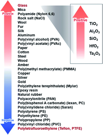
A table of the relative permittivity of several oxide dielectric materials is shown in Fig. 2. The triboelectric series is considered as a basic reference to select proper materials for TENGs. From the triboelectric series, it is possible to estimate which side will be negatively or positively charged when a triboelectric charge is generated by friction between two different materials. Since there is limited data for the above-mentioned oxide materials, a triboelectric series consisting of SiO2, Al2O3, HfO2, Ta2O5 and TiO2 was made experimentally. The series was made by comparing the measured Voc values of the TENGs using 10 combinations of two oxide materials. All of the Voc data showed very low Voc values, from 0.1 V to 1.7 V (Fig. S1†), which means the triboelectric polarities of the above-mentioned oxide materials have very small differences. The Voc values were also measured with a reversed connection of the electrodes to make sure that the generated pulses were from the TENGs. The most positively charged oxide material was TiO2, followed by Al2O3, SiO2 and HfO2, and the most negatively charged oxide material was Ta2O5.
 | ||
| Fig. 2 A conventional triboelectric series and an experimentally determined triboelectric series of oxide dielectric materials. | ||
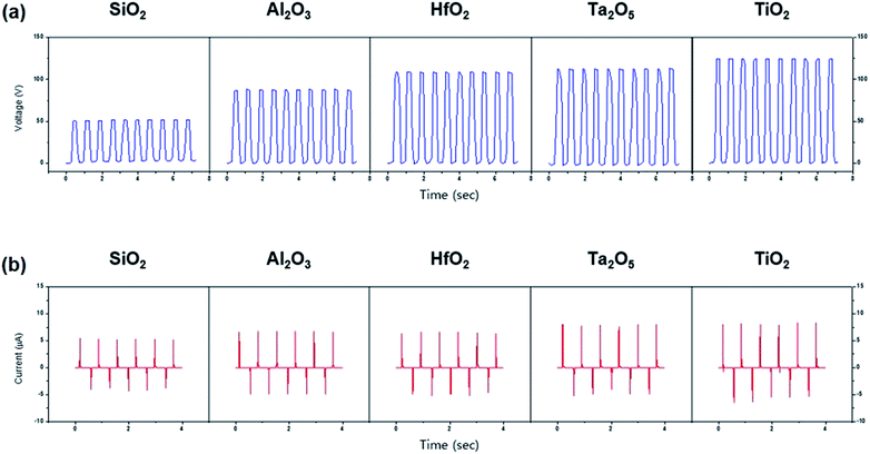
The oxide thin films with a thickness of 300 nm were used as the positive tribo-materials. PTFE film with a thickness of 50 μm was used as the counter tribo-material. The electrical data for the fabricated TENGs are shown in Fig. 3. Voc was measured using a Keithley 6514B electrometer, and Isc was measured using a Keithley 6485 picoammeter and a Tektronix DPO 2024 oscilloscope. The Voc values of SiO2, Al2O3, HfO2, Ta2O5 and TiO2 are, respectively, 50.2 V, 87.2 V, 109.3 V, 114.5 V and 124.1 V (Fig. 3a), and the Isc values are 3.92 μA, 5 μA, 5.12 μA, 6.24 μA and 14.88 μA (Fig. 3b). Both Voc and Isc showed a general tendency to increase as the relative permittivity increases.
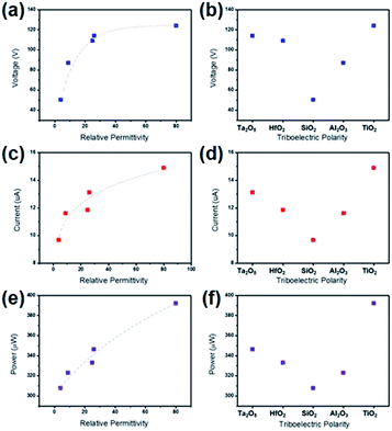
As shown in Fig. 4, the measured electrical data were plotted as a function of the relative permittivity and triboelectric polarity according to the organized triboelectric series. The maximum instantaneous power of the thin film (TF) TENGs was measured as 307.58 μW, 322.86 μW, 333.09 μW, 346.29 μW and 392.08 μW in order of relative permittivity. In contrast to the common understanding of the triboelectric series, the performance of the oxide TF TENGs does not follow the order of triboelectric polarity (Fig. 4b, d and f). Instead, the higher the relative permittivity of the material, the better the performance achieved (Fig. 4a, c and e). This result indicates that the relative permittivity is considered to be a more dominant factor than the triboelectric polarity which affects the electrical output of TENGs. Consequently, when the variation of triboelectric polarity is small, the electrical output is more dependent on the relative permittivity than the triboelectric polarity.
 | ||
| Fig. 4 Plotted Voc, Isc and power data as a function of (a–c) relative permittivity and (d–f) triboelectric polarity. | ||
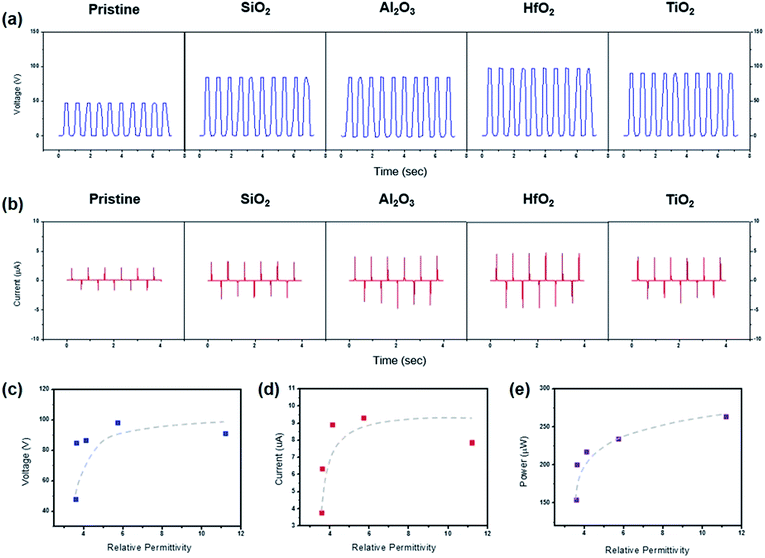
The same principle can be applied to composite materials. PMMA was chosen as a matrix for this experiment as it can be made into composites with ease, and it is located on the positive side of the triboelectric series. The fillers for the composites were SiO2, Al2O3, HfO2 and TiO2 nanoparticles (NPs). The morphologies of the NPs were observed using a scanning electron microscope (SEM) (Fig. S2†). The electrical data for the composite TENGs are shown in Fig. 5. The Voc values of the TENGs using PMMA composites consisting of SiO2 NPs, Al2O3 NPs, HfO2 NPs and TiO2 NPs are, respectively, 84.7 V, 86.3 V, 97.9 V and 90.7 V, while pristine PMMA had a Voc of 47.5 V (Fig. 5a). Isc showed a similar tendency to Voc, with values of 6.32 μA, 8.88 μA, 9.28 μA and 8.16 μA, while pristine PMMA had an Isc of 3.76 μA (Fig. 5b). The maximum instantaneous power data were measured as 153.63 μW, 200.04 μW, 216.36 μW, 236.33 μW and 262.94 μW, respectively (Fig. 5e). The results generally show a similar tendency to the experiment using pure oxide thin films, with some exceptions (Fig. 5c–e). Since the composite materials exhibit more complex structures compared to the pure materials, many factors such as the roughness of the surface and/or the effects generated at the interface between the fillers and the matrix can also affect the electrical outputs and results, with exceptions. However, both sets of results from the thin films and composites were well-matched with our theoretical prediction of the dependence of performance on the permittivity of the oxide materials.
Experimental
Preparation of the tribo-materials
A thin film of Al (60 nm) was deposited on a purchased PTFE film (50 μm) using a thermal evaporator. Al2O3, HfO2, Ta2O5 and TiO2 thin films (300 nm) were deposited by sputtering on a doped silicon substrate. The working power was 1000 W at 10−8 Torr. The SiO2 thin film (300 nm) was synthesized by oxidizing a Si wafer. As shown in Fig. S3,† the composition of each oxide material was analyzed by X-ray photoelectron spectrometry (XPS). The PMMA composite films were synthesized by the following method. SiO2 (ε = 3.9), Al2O3 (ε = 9), HfO2 (ε = 25) and TiO2 (ε = 80) nanoparticles were purchased from Sigma Aldrich. For uniform composite films, the oxide nanoparticles were dispersed in ethanol and sonicated for 30 min. Each dispersion solution was mixed with PMMA 495 and mechanically stirred at 348 K for 6 h in order to evaporate the ethanol completely. The volume ratio of nanoparticles to PMMA was 1![[thin space (1/6-em)]](https://www.rsc.org/images/entities/char_2009.gif) :
:![[thin space (1/6-em)]](https://www.rsc.org/images/entities/char_2009.gif) 10. Each suspension was spin-coated on a doped Si wafer and baked at 453 K for 2 min.
10. Each suspension was spin-coated on a doped Si wafer and baked at 453 K for 2 min.
Characterization
The deposition of the oxide thin films was confirmed by X-ray photoelectron spectroscopy (XPS) with a K-alpha (Thermo VG, UK) instrument at room temperature using a monochromatic Al X-ray source at 12 kV and 3 mA. The sample analysis chamber of the XPS instrument was maintained at a pressure of 4.8 × 10⁻⁹ mbar. The electrical outputs of the TENGs were measured using a Keithley 6485 picoammeter, a Tektronix DPO 2024 oscilloscope and a Keithley 6514B electrometer for low-noise and precise current/voltage measurements under a vertical load of 3–5 N with a frequency of 1.25 Hz. The separation distance between two plates was 4 mm.Conclusions
The influence of the relative permittivity of dielectric materials on the performance of TENGs, by controlling the positive plate with various oxide materials, has been demonstrated. SiO2 (εr = 3.9), Al2O3 (εr = 9), HfO2 (εr = 25), Ta2O5 (εr = 26) and TiO2 (εr = 80) were selected as pure oxide tribo-materials. From the most negative to the most positive, the oxides are listed in the order of Ta2O5, HfO2, SiO2, Al2O3 and TiO2. PMMA composite TENGs were also fabricated using SiO2, Al2O3, HfO2 and TiO2 NPs. The measured Voc, Isc and power values of the TENGs showed a general tendency to increase with an increase in the relative permittivity, while scattered data were observed as a function of the triboelectric polarity. In other words, the relative permittivity is considered to be a more dominant factor than the triboelectric polarity in this study. This work provides a better understanding of the factors affecting the performance of TENGs from the view of the materials. By considering the relative permittivity, it will be possible to broaden the range of selectable tribo-materials and the subsequent applications.Conflicts of interest
There are no conflicts to declare.Acknowledgements
This work is supported by the National Research Foundation of Korea (NRF) grant funded by the Korean government (MSIP) (No. 2017R1A2B3011586), the Nano-Material Technology Development Program through the National Research Foundation of Korea (NRF) funded by the Ministry of Education, Science and Technology (2014M3A7B4051594), the third Stage of Brain Korea 21 Plus Project in 2017, and the Yonsei University Yonsei-SNU Collaborative Research Fund of 2014.References
- Z. Zhao, X. Pu, C. Du, L. Li, C. Jiang, W. Hu and Z. L. Wang, ACS Nano, 2016, 10, 1780 CrossRef CAS PubMed.
- Y. Yang, G. Zhu, H. Zhang, J. Chen, X. Zhoung, Z. H. Lin, Y. Su, P. Bai, X. Wen and Z. L. Wang, ACS Nano, 2013, 6, 9461 CrossRef PubMed.
- X. Wang, S. Niu, Y. Yin, F. Yi, S. You and Z. L. Wang, Adv. Energy Mater., 2015, 5, 1501467 CrossRef.
- D. Bhatia, W. Kim, S. Lee, S. W. Kim and D. Choi, Nano Energy, 2017, 33, 515 CrossRef CAS.
- F. R. Fan, Z. Q. Tian and Z. L. Wang, Nano Energy, 2012, 1, 328 CrossRef CAS.
- Z. L. Wang, L. Lin, J. Chen, S. Niu and Y. Zi, Triboelectric Nanogenerators, Springer, Switzerland, 2016 Search PubMed.
- Y. Zi, J. Wang, S. Wang, S. Li, Z. Wen, H. Guo and Z. L. Wang, Nat. Commun., 2016, 7, 10987 CrossRef CAS PubMed.
- S. Wang, L. Lin and Z. L. Wang, Nano Lett., 2012, 12, 6339 CrossRef CAS PubMed.
- S. Niu and Z. L. Wang, Nano Energy, 2015, 14, 161 CrossRef CAS.
- S. Niu, S. Wang, L. Lin, Y. Liu, Y. S. Zhou, Y. Hu and Z. L. Wang, Energy Environ. Sci., 2013, 6, 3576 Search PubMed.
- S. Niu, Y. Liu, S. Wang, L. Lin, Y. S. Zhou, Y. Hu and Z. L. Wang, Adv. Mater., 2013, 25, 6184 CrossRef CAS PubMed.
- B. Yang, W. Zeng, Z. H. Peng, S. R. Liu, K. Chen and X. M. Tao, Adv. Energy Mater., 2016, 6, 1600505 CrossRef.
- S. M. Kim, J. Ha and J. B. Kim, Integr. Ferroelectr., 2016, 176, 283 CrossRef CAS.
- S. Wang, L. Lin, Y. Xie, Q. Jing, S. Niu and Z. L. Wang, Nano Lett., 2013, 13, 2226 CrossRef CAS PubMed.
- G. Zhu, J. Chen, Y. Liu, P. Bai, Y. S. Zhou, Q. Jing, C. Pan and Z. L. Wang, Nano Lett., 2013, 13, 2282 CrossRef CAS PubMed.
- Y. Yang, Y. S. Zhou, H. Zhang, Y. Liu, S. Lee and Z. L. Wang, Adv. Mater., 2013, 25, 6594 CrossRef CAS PubMed.
- Y. Yang, H. Zhang, J. Chen, Q. Jing, Y. S. Zhou, X. Wen and Z. L. Wang, ACS Nano, 2013, 7, 7342 CrossRef CAS PubMed.
- S. Niu, Y. Liu, S. Wang, L. Lin, Y. S. Zhou, Y. Hu and Z. L. Wang, Adv. Funct. Mater., 2014, 24, 3332 CrossRef CAS.
- S. Wang, Y. Xie, S. Niu, L. Lin and Z. L. Wang, Adv. Mater., 2014, 26, 2818 CrossRef CAS PubMed.
- B. Meng, W. Tang, Z. H. Too, X. Zhang, M. Han, W. Liu and H. Zhang, Energy Environ. Sci., 2013, 6, 3235 Search PubMed.
- F. R. Fan, L. Lin, G. Zhu, W. Z. Wu, R. Zhang and Z. L. Wang, Nano Lett., 2012, 12, 3109 CrossRef CAS PubMed.
- L. Lin, S. Wang, Y. Xie, Q. Jing, S. Niu, Y. Hu and Z. L. Wang, Nano Lett., 2013, 13, 2916 CrossRef CAS PubMed.
- S. Niu, Y. Liu, X. Chen, S. Wang, Y. S. Zhou, L. Lin, Y. Xie and Z. L. Wang, Nano Energy, 2015, 12, 760 CrossRef CAS.
- G. Zhu, Z. H. Lin, Q. Jing, P. Bai, C. Pan, Y. Yang, Y. Zhou and Z. L. Wang, Nano Lett., 2013, 13, 847 CrossRef CAS PubMed.
- Z. H. Lin, G. Cheng, W. Wu, K. C. Pradel and Z. L. Wang, ACS Nano, 2014, 8, 6440 CrossRef CAS PubMed.
- J. Chen, H. Guo, X. He, G. Liu, Y. Xi, H. Shi and C. Hu, ACS Appl. Mater. Interfaces, 2016, 8, 736 CAS.
- X. J. Zhao, G. Zhu and Z. L. Wang, ACS Appl. Mater. Interfaces, 2015, 7, 6025 CAS.
- J. Zhong, Q. Zhong, F. Fan, Y. Zhang, S. Wang, B. Hu and Z. L. Wang, Nano Energy, 2013, 2, 491 CrossRef CAS.
- Z. H. Lin, Y. Xie, Y. Yang, S. Wang, G. Zhu and Z. L. Wang, ACS Nano, 2013, 7, 4554 CrossRef CAS PubMed.
- R. Kronig, Textbook of Physics, Pergamon Press London, New York, 1959 Search PubMed.
Footnote |
| † Electronic supplementary information (ESI) available. See DOI: 10.1039/c7ra07274k |
| This journal is © The Royal Society of Chemistry 2017 |


