
 Open Access Article
 This Open Access Article is licensed under a
 Creative Commons Attribution 3.0 Unported Licence
Study on the preparation and performance of low gas permeability trifluoropropyl phenyl silicone rubber
Huaijun Zhu ab,
Zilin Daib and
Weiping Tu*a
ab,
Zilin Daib and
Weiping Tu*a
aSchool of Chemistry and Chemical Engineering, South China University of Technology, Guangzhou 510640, China. E-mail: cewptu@scut.edu.cn
bGuangdong Research Institute of Rare Metals, Guangdong Academy of Sciences, Guangzhou 510651, China
First published on 15th August 2017
Abstract
In order to overcome the defects of opacity, high gas permeability, poor heat and solvent oil resistance of methyl silicone rubber, optically transparent trifluoropropyl phenyl silicone rubber was prepared by introducing trifluoropropyl and phenyl to organic silicone molecules. Then organic polysilazane (OPSZ) was coated on the trifluoropropyl phenyl silicone rubber surface with tetramethylhexamethylenediamine as a catalyst and a dense coating with low gas permeability was achieved. This process realized low-temperature curing and siliceous transition. At the same time, optical performance, mechanical properties, oxygen permeation flux, and anti-sulfuration were measured. The results showed that the fluorine-containing phenyl silicone rubber had good optical transparency, tensile strength, elongation at break, tear strength, oil resistance and heat resistance. The OPSZ coating surface was continuous, uniform, dense and free of cracks and voids; meanwhile, the coating section was dense, uniform, seamless, without cracks. The interface between the coating and the silicone rubber exhibited good adhesion. Light transmission was over 92% between 400 and 800 nm. When the coating thickness was more than 12 μm, the oxygen permeation flux remained unchanged, lamps had good anti-sulfuration ability, and luminous flux was maintained at over 99.8%. when the mass fraction of tetramethyl hexamethylene diamine (w) was over 5%, siliceous transition was achieved under room temperature and 50% relative humidity for 24 h.
1 Introduction
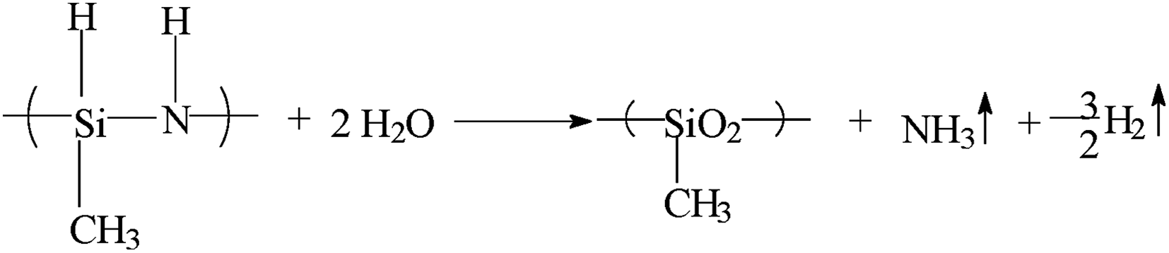
Silicone rubber can be used in packaging and sealing of precise electronic components, chips, LEDs, solar cells, fuel cells, medicine, etc. due to excellent properties of high-temperature resistance, radiation resistance, anti-UV, and anti-ageing.1–6 But low gas permeability is required, because permeable gases – particularly, oxygen, hydrogen sulphide, and sulphur vapour – can easily cause oxidation and sulfuration of electronic components, chips, electrodes, medicines, etc. and shorten their service lives.Some researchers have achieved good results in improving the gas barrier by coating or depositing dense inorganic materials such as nano-silica on the rubber surface.7,8 Siliceous coating made from polysilazane has excellent gas barrier properties and has been widely used in electronic protection and chip packaging. Therein, perhydropolysilazane (PHPS) has high reactivity and can be hydrolyzed or oxidized to form SiON at low temperature, and the resulting coating is of high transparency, hardness, and density. But PHPS releases ammonia and hydrogen during curing, along with weight loss and changes in density. With increasing thickness, the volume change increases inner stress of the coating, resulting in crack formation on the coating.9–11
Organic polysilazane (OPSZ) easily forms a thick elastic coating due to the introduction of organic groups to molecular chains, increasing flexibility and reducing volume shrinkage, but conversion to a siliceous coating is very slow and requires baking at more than 300 °C. Such high temperatures will inevitably lead to coated polymer oxidation, cracking and even carbonisation. Therefore, we wish to find a catalyst to realize low-temperature curing and siliceous transition and reduce gas permeability of the polymer.
Typically, silicone rubber is based on linear silicone oil and added silicone resin or silica as reinforcing fillers to improve mechanical properties. In order to obtain optically transparent silicone rubber, silicone resin with a refractive index matching that of silicone oil is needed. For silica reinforcement system, silicone oil with a refractive index matching that of silica is needed. Usually, silicone rubber cannot exhibit optical transparency due to differences in refractive index of silica and silicone oil, and hence, it cannot be applied to optical fields.
Phenyl silicone rubber has excellent heat resistance, but poor solvent resistance. Fluorine-containing silicone rubber has excellent solvent resistance but poor heat resistance. Fluorine-containing phenyl silicone rubber combines the advantages of phenyl silicone rubber and fluorine-containing silicone rubber, providing good tensile strength, elongation at break and tear strength, and at the same time, it has excellent oil resistance and heat resistance.
In this paper, optically transparent trifluoropropyl phenyl silicone rubber was prepared by introducing phenyl and trifluoropropyl to organic silicone molecules in order to overcome the defects of opacity, high gas permeability, no enduring high temperature and oil of methyl silicone rubber. OPSZ was coated on the silicone rubber surface with tetramethylhexamethylenediamine as a catalyst and a dense coating with low gas permeability was achieved. This process realized low-temperature curing and siliceous transition. Optical performance, mechanical properties, oxygen permeation flux, and anti-sulfuration were measured in an attempt to resolve oxidation and sulfuration of electronic components, chips, electrodes, medicines, etc.
2 Materials and methods
2.1 Materials
Octaphenyl cyclotetrasiloxane (purity of 99.7%) was purchased from Shaoguan Yueyouyan Chemical Technology Co. Ltd., China. Fluorine-containing hydroxy silicone oil (viscosity = 300 mPa s, volatility < 0.5%) was purchased from Weihai Xinyuan Chemical Co. Ltd., China. Vinyl-terminated silicone oil (viscosity = 1000 mPa s, volatility < 0.5%) was purchased from Jiangxi Xinghuo Chemical Factory, China. Dimethyl silicone oil (volatility < 0.5%), high-hydro silicone oil (hydrogen content of 1.58%, volatility < 0.5%) and hydrophobic fumed silica (HDK H20) were purchased from Wacker Chemical Co. Ltd., China. Nitrogen and ammonia (content > 99%) were purchased from Guangzhou Shiyuan Gas Co., Ltd., China. Chemically pure tetramethylhexamethylenediamine, tetramethylethylenediamine, hexamethylenediamine, m-xylylenediamine, and trimethylenebis (N-methylpyridine) were purchased from Aladdin Industrial Co., China. Platinum catalyst (platinum content of 5000 ppm) was purchased from Shanghai Heraeus Industrial Technology Materials Co., Ltd., China. Chemically pure dibutyl ether and pyridine were purchased from Sun Chemical Technology Co., Ltd., China. Methyl vinyl MQ silicone resin (vinyl content of 1.5%, viscosity of 8000 mPa s, refractive index of 1.41, volatility < 0.3%); methyl hydrogen silicone oil (hydrogen content of 0.8%, viscosity of 80 mPa s, refractive index of 1.41, volatility < 0.3%); and vinyl silicone oil (vinyl content of 0.135%, viscosity of 10![[thin space (1/6-em)]](https://www.rsc.org/images/entities/char_2009.gif) 000 mPa s, refractive index of 1.41, volatility < 0.1%) were synthesized by us. Other reagents were chemically pure grade.
000 mPa s, refractive index of 1.41, volatility < 0.1%) were synthesized by us. Other reagents were chemically pure grade.
2.2 Methods
Synthesis of fluorine-containing phenyl hydrogen silicone oil. The following substances were added to a 2 L three-necked flask: 150 g methyl silicone oil with viscosity of 5 mPa s, 250 g octaphenyl cyclotetrasiloxane, and 100 g fluorine-containing hydroxy silicone oil. The mixture was stirred until uniform, and then 0.5 g potassium hydroxide was added. The flask was heated to 160 °C for 7 hours and then cooled to room temperature. Into the flask, 50 g sulphuric acid (content of 98%), 800 g methylcyclohexane and 500 g methyl hydrogen silicone oil were added and stirred at room temperature for 5 hours; then 200 g sodium carbonate was added to neutralise the sulphuric acid until pH = 7. The mixture was vacuum filtered and the solvent was removed to yield a colourless and transparent fluorine-containing phenyl hydrogen silicone oil, with hydrogen content of 0.78%, refractive index of 1.4605, viscosity of 425 mPa s (labelled as FBH-1).
By adjusting the ratio of raw materials, fluorine-containing phenyl hydrogen silicone oil with refractive indexes of 1.42, 1.44, 1.48 and 1.50 were obtained (labelled as FBH-2, FBH-3, FBH-4, and FBH-5, respectively).
Synthesis of fluorine-containing phenyl vinyl silicone oil. The following substances were added to a 2 L three-necked flask: 200 g vinyl silicone oil with viscosity of 1000 mPa s, 500 g octaphenyl cyclotetrasiloxane and 300 g fluorine-containing hydroxy silicone oil. The mixture was stirred until uniform, and then 0.8 g lithium hydroxide was added. The flask was heated to 160 °C for 7 hours and then cooled to room temperature. Into the flask, 800 g methylcyclohexane and 1.1 g acetic acid were added and stirred for 1 hour; then 2.2 g sodium bicarbonate was added to neutralise the excessive acetic acid. The mixture was vacuum filtered and the solvent was removed to yield a colourless and transparent fluorine-containing phenyl vinyl silicone oil, with the refractive index of 1.4602, viscosity of 12
240 mPa s (labelled as FBV-1).By adjusting the ratio of raw materials, fluorine-containing phenyl vinyl silicone oil with refractive indexes of 1.42, 1.44, 1.48, and 1.50, were obtained (labelled as FBV-2, FBV-3, FBV-4, and FBV-5, respectively).
Preparation of fluorine-containing phenyl silicone rubber films. About 100 parts of the fluorine-containing phenyl vinyl silicone oil and 40 parts of hydrophobic fumed silica were added into a kneader, and kneaded at 140 °C and 0.08 MPa for 4 hours. Then the mixture was cooled and packaged. Some amounts of the mixture, fluorine-containing phenyl vinyl silicone oil, and fluorine-containing phenyl hydrogen silicone oil, platinum catalyst were taken together and stirred until uniform. This mixture was then poured into molds (10 cm × 4 cm × 2 mm) and vacuum deaerated until there were no residual air bubbles. Finally, the molds were placed in an oven and baked at 100 °C for 2 hours and at 150 °C for 3 hours sequentially, and then cooled to room temperature to give films of trifluoropropyl phenyl silicone rubber with hardness of 70 A.
Preparation of methyl silicone rubber films. Methyl vinyl MQ silicone resin, methyl hydrogen silicone oil, vinyl silicone oil, and platinum catalyst were mixed in proportion and stirred until uniform. These mixtures were then poured into molds (10 cm × 4 cm × 2 mm), and vacuum deaerated until there were no residual air bubbles. Finally, the molds were placed in an oven and baked at 100 °C for 2 hours and 150 °C for 3 hours, and then cooled to room temperature to give cured methyl silicone rubber films with a hardness of 70 A.
Preparation of packaged LED lamps. Trifluoropropyl phenyl silicone rubbers were packaged on 5050 chips. Then, they were placed in an oven and baked at 100 °C for 2 hours and 150 °C for 3 hours, and then cooled to room temperature to give packaged LED lamps.
Preparation of OPSZ. A 1 litre four-necked flask fixed with an intake duct, mechanical stirrer and condenser was used as reactor. Nitrogen, 200 mL of pyridine, and 28.75 g of methylhydrogen dichlorosilane were added to the four-necked flask, and then 20 g of ammonia gas was slowly pumped in. The mixture reacted in an ice-water bath for 4 hours, and then dry nitrogen was pumped into the flask for 30 minutes to remove excess ammonia. The mixture was vacuum filtered and the solvent was removed under −0.098 MPa and 180 °C to yield 13.86 g of colorless transparent OPSZ, the yield being 93.96%.
Preparation of OPSZ solution. Under dry nitrogen, 80 g dibutyl ether and 20 g OPSZ were added to a 100 mL three-necked flask and stirred with a stirrer; then 1 g of tetramethylhexamethylenediamine was added, stirring for 1 h. A colorless, transparent OPSZ solution was obtained.
Preparation of OPSZ coatings. OPSZ solution was brushed onto the silicone rubber films and the packaged LED lamps surface, with single or multiple brushing as needed. OPSZ would convert into a siliceous coating after curing at room temperature with 50% relative humidity for 24 hours.
3 Results and discussion
3.1 Structure analysis
Because of the large deviation in refractive index among methyl silicone oil, octaphenyl cyclotetrasiloxane and fluorine-containing hydroxy silicone oil, they formed an opaque mixture when they were mixed directly. A colourless and transparent product was obtained because breaking and rearrangement of molecular chains improve homogeneity of phase. Thus, we can judge whether the raw materials reacted by transparency (see Fig. 1 below).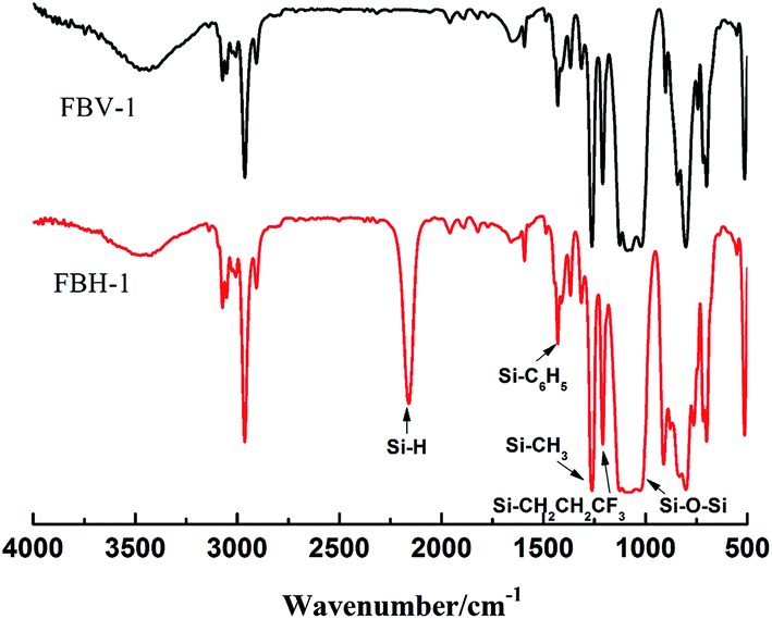 | ||
| Fig. 1 FT-IR spectra of FBH-1 and FBV-1. | ||
As can be seen in Fig. 1, 1431 cm−1 and 1080 cm−1 were the characteristic peaks of Si–C6H5, 1255 cm−1 was the characteristic peak of Si–CH3, 1210 cm−1 was the characteristic peak of Si–CH2CH2CF3, 1085 cm−1 was the characteristic peak of Si–O–Si, 2135 cm−1 was the characteristic peak of Si–H, and the characteristic peak of Si–Vi was not obvious due to the presence of phenyl, indicating that the products obtained in this study were fluorine-containing phenyl hydrogen silicone oil and fluorine-containing phenyl vinyl silicone oil.
3.2 Optical properties of fluorine-containing phenyl silicone rubber
Methyl silicone rubbers reinforced by fumed silica were not optically transparent due to the deviation in refractive index between methyl silicone oil and fumed silica. If the refractive index of silicone oil was similar or identical to fumed silica, we could obtain an optically transparent silicone rubber. The introduction of phenyl can increase the refractive index of silicone oil and trifluoropropyl can reduce the refractive index. By adjusting the ratio of phenyl and trifluoropropyl, we can obtain specific content and refractive index of fluorine-containing phenyl silicone oil.Fig. 2 shows the transmittance of the fluorine-containing phenyl silicone rubber prepared by different refractive indexes of silicone oil and fumed silica at 450 nm, m (fumed silica)/m (silicone oil) = 30:70, thickness 2 mm.
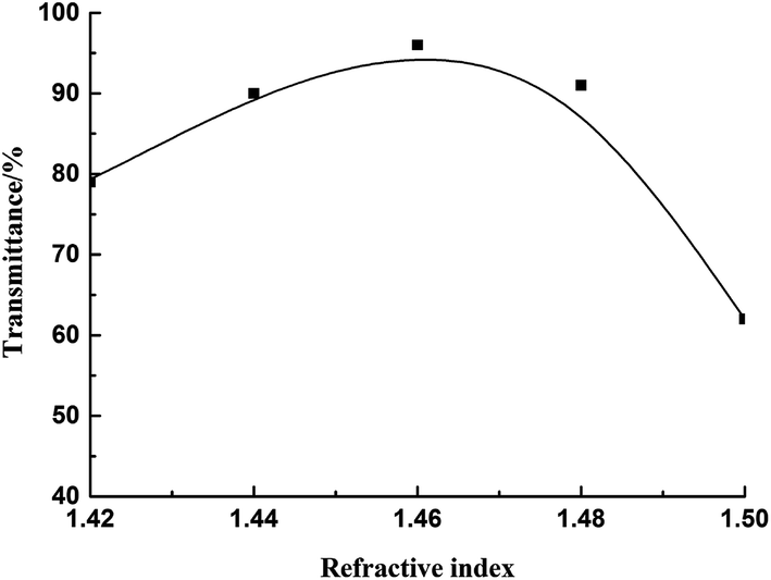 | ||
| Fig. 2 Transmittance of the fluorine-containing phenyl silicone rubber prepared by different refractive indexes of silicone oil and fumed silica at 450 nm. | ||
As can be seen in Fig. 2, when the refractive index of the fluorine-containing phenyl silicone oil was 1.46 ± 0.01, the transmittance was over 92%, and the rubber obtained was optically transparent. When the refractive index of the silicone oil was 1.46, the transmittance was the highest, up to 96%. Therefore, it is necessary to select silicone oil with refractive index of 1.46 to get the best transmittance.
A heterogeneous phase was formed when the refractive index of silicone oil did not match that of fumed silica. When light beam was passed through the rubber, part of the beam deviated from the original direction of spread due to scattering, and the rubber appeared opaque. When the refractive indexes of both were similar or identical, the beam was considered to spread in homogeneous media, and the scattering was too weak to observe, and the rubber appeared transparent.
Fig. 3 shows the transmittance of fluorine-containing phenyl silicone rubber with a refractive index of 1.46 at different wavelengths.
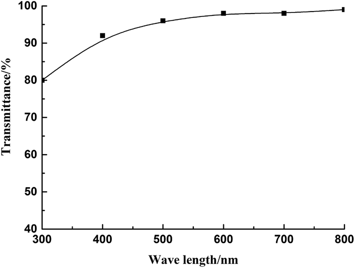 | ||
| Fig. 3 Transmittance of rubber with a refractive index of 1.46 at different wavelengths. | ||
As seen in Fig. 3, at 300 nm, the transmittance was 80%, and at the visible wavelength of 400–800 nm, the transmittance was over 92%. The result showed that the rubber films had good transmittance at visible wavelength. The pictures of silicone oils and cured rubber are shown in Fig. 4.
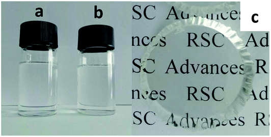 | ||
| Fig. 4 Pictures of silicone oils (a and b) and cured rubber (c). (a) Fluorine-containing phenyl vinyl silicone oil, (b) fluorine-containing phenyl hydrogen silicone oil, (c) fluorine-containing phenyl silicone rubber. | ||
3.3 Mechanical properties
Samples were prepared according to Method 1.3.3; the ratio of n(Si–CH = CH2)/n (Si–H) was controlled at 1:1.1, 1:1.2, 1:1.3, 1:1.4, and 1:1.5 (labelled as R1, R2, R3, R4, and R5, respectively). The mechanical performance test results are shown in Table 1.
| Samples | Standard | R1 | R2 | R3 | R4 | R5 |
|---|---|---|---|---|---|---|
| Hardness (25 °C) | GB/T531.1-2008 | 65 A | 68 A | 70 A | 72 A | 73 A |
| Tensile strength (25 °C), MPa | GB/T528-2009 | 5.4 | 5.3 | 5.5 | 6.5 | 6.8 |
| Tensile strength (280 °C × 1000 h), MPa | GB/T528-2009 | 4.0 | 4.0 | 4.2 | 4.1 | 4.3 |
| Elongation at break (25 °C), % | GB/T528-2009 | 350 | 390 | 420 | 380 | 340 |
| Elongation at break (280 °C × 1000 h), % | GB/T528-2009 | 240 | 230 | 220 | 220 | 210 |
| Tear strength (25 °C), kN m−1 | GB/T529-1999 | 22 | 24 | 23 | 24 | 26 |
| Tear strength (280 °C × 1000 h), kN m−1 | GB/T529-1999 | 18 | 19 | 17 | 18 | 21 |
| Oil resistance, C oil, Δm/% (25 °C × 72 h) | GB/T1690-2009 | 6.68 | 6.43 | 6.35 | 6.48 | 6.64 |
| Oil resistance, C oil, Δv/% (25 °C × 72 h) | GB/T1690-2009 | 7.23 | 7.62 | 7.68 | 7.53 | 7.75 |
As can be seen in Table 1, the cured fluorine-containing phenyl silicone rubber was of the tensile strength > 5.3 MPa, elongation at break > 340%, and tear strength > 22 kN m−1 at 25 °C, with excellent performance. After immersion in C oil at 25 °C for 72 hours, the largest volume change was of 7.75% and mass change of 6.68%, with good oil resistance. After high-temperature ageing at 280 °C for 1000 hours, we obtained tensile strength > 4.0 MPa, elongation at break > 210%, and tear strength > 17 kN m−1, with good heat resistance.
3.4 Curing mechanism of OPSZ
Chemical structure of OPSZ is as below.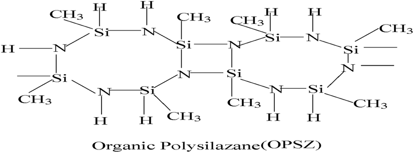
Curing mechanism of OPSZ is as below.
In the chemical structure of OPSZ, the electronegativity of Si and N atoms have a difference of 1.2, and the Si–N bond is between the Si–C and Si–O bonds, similar to the Si–Cl bond, so the Si–N bond has ionic bond characteristics. OPSZ forms a quadrilateral structure in the molecular centre, and the structure is unstable because of large tension; therefore, the Si–N bond is readily converted to other bonds.
Fig. 5 shows the sketch map of cured silicone rubber and low gas permeability coating.
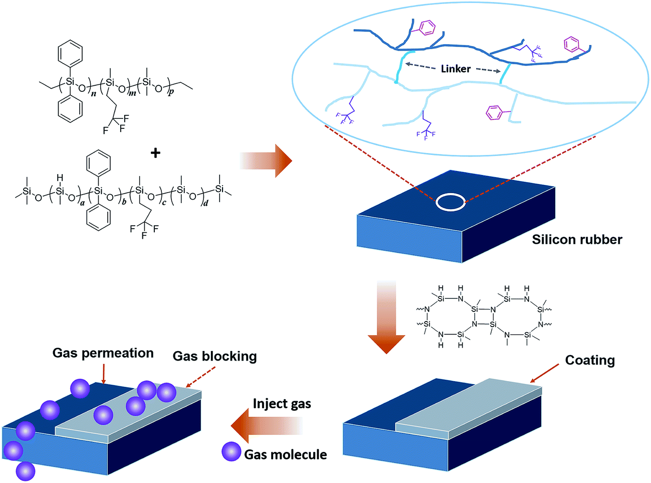 | ||
| Fig. 5 Sketch map of cured silicone rubber and low gas permeability coating. | ||
3.5 Structure characterisation
Fig. 6 shows the infrared spectra of OPSZ before Fig. 6(a) and after Fig. 6(b) curing; 3400 cm−1 and 1180 cm−1 were the characteristic peak of N–H, 2160 cm−1, 1261 cm−1, 820–1020 cm−1 were the characteristic peaks of Si–H, Si–CH3, and Si–N, respectively. All confirmed that the product contained Si–H, Si–CH3, N–H and Si–N bonds.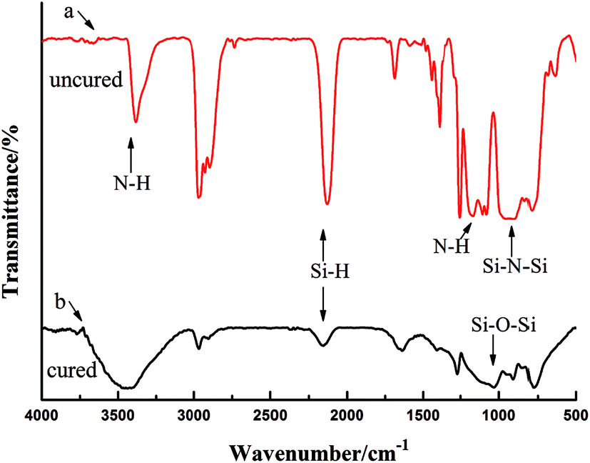 | ||
| Fig. 6 Infrared spectra of OPSZ before (a) and after (b) curing. | ||
Fig. 6(b) shows the infrared spectrum of OPSZ after curing. As can be seen, the characteristic peaks of the N–H bond at 3400 cm−1 and at 1180 cm−1 were reduced and the characteristic peak of Si–H bond at 2160 cm−1 and that of Si–N–Si bond at 820–1020 cm−1 decreased significantly, with the formation of a new characteristic peak of Si–O–Si bond at 1080 cm−1, thus indicating that the Si–H and Si–N bonds had converted to Si–O bonds.
3.6 Surface and section appearance of coating
Surface and section appearance of coatings were characterised by SEM (see Fig. 7 below).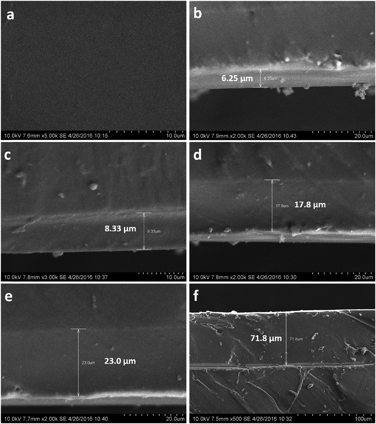 | ||
| Fig. 7 Surface (a) and section (b–f) morphology of coatings. | ||
Photograph Fig. 7(a) is the surface appearance of coating, and as can be seen, the coating surface was continuous, uniform, dense, crack-free and void. Photographs Fig. 7(b) to (f) are section appearances of coatings; Fig. 7(b) to (e) show that the thickness of the coating increased, but the coatings were still dense, seamless and crack-free, indicating that the coating had excellent adhesion to silicone rubber. But with increasing thickness of the coating, as in Fig. 7(f), there was a clear crack between the silicone rubber and coating, indicating that the adhesion between the coating and silicone rubber deteriorated. OPSZ released ammonia and hydrogen during curing, along with weight loss and changes in density. With increasing thickness, the volume change increased the inner stress of the coating, resulting in the coating becoming cracked. The experiments found that the interface between the coating and silicone rubber exhibited good adhesion when the coating thickness was less than 32–35 μm.
Generally, PHPS coating has a thickness from tens to hundreds of nanometers; when the coating thickness exceeds 1–2 μm, coating cracks due to volume contraction.8 PHPS coating is of high hardness and rigidity, and can only be coated on a hard substrate surface. Any polymer surface having slight elasticity cannot be coated, because a polymer is easily deformed and the coatings are easily crack and peel. In contrast, OPSZ coating has flexibility due to the introduction of methyl and is not brittle when a slight deformation occurs, thus maintaining good adhesion. However, due to the introduction of a methyl group, the density of an OPSZ coating is lower than a PHPS coating. For the same coating thickness, the gas barrier property of OPSZ coating is inferior to that of PHPS coating, but we can increase thickness to overcome this. With increasing thickness, gas permeability and diffusion paths in the coating increases and the ability of gas to permeate and diffuse is decreases.
3.7 Oxygen permeation flux
The tests were carried out according to 2.2.3. Table 2 displays the test results.| Samples | Coating thickness/μm | Oxygen permeation flux/cm3 m2, 24 h 0.1 MPa |
|---|---|---|
| Before coating (methyl silicone rubber) | 0 | 12500 |
| After coating (methyl silicone rubber) | 12.1 | 1.4 |
| Before coating (trifluoropropyl phenyl silicone rubber) | 0 | 280 |
| After coating (trifluoropropyl phenyl silicone rubber) | 12.4 | 1.3 |
Table 2 shows that before coating, methyl silicone rubber had the maximum oxygen permeation flux. This was because the molecular chains of methyl silicone rubber were spiral, the side chains of methyl were relatively isolated, and the intermolecular forces were so weak that molecular chains could rotate easily and oxygen could freely permeate. For fluorine-containing phenyl silicone rubber, the interaction forces increased because phenyl has a larger molecule structure and trifluoropropyl contains a longer carbon chain, which can twine and overlap. A high-electron-density barrier layer was formed around the molecular chains, especially the fluorine atom, which has a very small radius, filling the voids in the molecule, so that the barrier layer became denser and stopped oxygen molecules from freely permeating among the molecular chains, resulting in decreased oxygen permeation flux; hence, gas permeability was lower than methyl silicone rubber.
After coating, methyl silicone rubber exhibited good gas barrier properties, and the oxygen permeation flux reduced to 0.0112% of that before coating. For fluorine-containing phenyl silicone rubber after coating, the oxygen permeation flux reduced to 0.4643% of that before coating. Although values of oxygen permeation flux had a ratio of 44.64 between fluorine-containing phenyl silicone rubber and methyl silicone rubber, they had the same oxygen permeation flux after coating. So, we conclude that a gas barrier occurs in the OPSZ coating, but is not related to the gas permeability of the substrate.
The cured OPSZ formed a carbonaceous Si–O layer on the surface of silicone rubber, with excellent density, and oxygen was impermeable to the inorganic layer and the gas barrier improved, thus exhibiting an excellent gas barrier effect.
In actual use, we found considerable influence of coating thickness on oxygen permeation flux, although the coating was too thin to reduce cracks, voids and other defects, especially for complex shapes. Due to surface roughness of the substrate, it was difficult for the coating to obtain complete coverage and the penetration and diffusion of oxygen in the coating were of shorter distances, causing a poor barrier effect. Only when the coating reached a certain thickness was oxygen blocked, preventing continued penetration and diffusion due to the obstruction of inorganic material particles, leading to excellent barrier properties. Fig. 8 shows the effect of coating thickness on oxygen permeation flux.
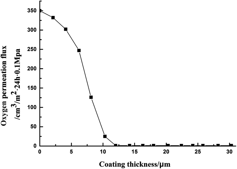 | ||
| Fig. 8 Influence of coating thickness on oxygen permeation flux. | ||
As can be seen, with increasing thickness of the coating, oxygen permeation flux decreased. With coating thickness of 12 μm or more, oxygen permeation flux remained unchanged, and after that, increasing the coating thickness had no effect on oxygen permeation flux. When the thickness was in the range 32–35 μm, volume changes increased internal stress of the coating, resulting in the coating becoming cracked. Therefore, the coating thickness should be controlled at 15–20 μm.
3.8 Sulfuration resistance
The tests were carried out according to 2.2.4. The results of the lamps photoelectronic test before and after sulfuration are shown in Table 3.| Package silicone rubber | Coating thickness/μm | Average optical power before sulfuration/10−2 W | Average optical power after sulfuration/10−2 W | Average flux maintenance rate after sulfuration/% |
|---|---|---|---|---|
| Before coating (methyl silicone rubber) | 0 | 2.142 | 1.400 | 65.21 |
| After coating (methyl silicone rubber) | 17.2 | 2.132 | 2.130 | 99.91 |
| Before coating (fluorine-containing phenyl silicone rubber) | 0 | 2.413 | 2.257 | 93.54 |
| After coating (fluorine-containing phenyl silicone rubber) | 17.8 | 2.404 | 2.402 | 99.92 |
As can be seen from Table 3, for lamps packaged by methyl silicone rubber before coating, the luminous flux maintenance was 65.21% after sulfuration. For lamps packaged by fluorine-containing phenyl silicone rubber before coating, the luminous flux maintenance was 93.54% after sulfuration. Lamps packaged by fluorine-containing phenyl silicone rubber after coating had good anti-sulfuration ability, and the luminous flux maintenance was over 99.9% after sulfuration.
This is because the cured OPSZ could form a carbonaceous Si–O layer on the surface of silicone rubber, with excellent density, and because sulfuric vapour was impermeable to the inorganic layer; thus, the gas barrier was improved and an excellent gas barrier effect was observed.
3.9 Influence of amine catalyst
OPSZ curing can be divided into three stages: (1) the coating became touch dry because of solvent evaporation and self-crosslinking characteristics of OPSZ; (2) the coating and moisture reacted, releasing hydrogen and ammonia and increasing density; and (3) there was no substantial loss of quality in forming a stable structure.The transition of OPSZ to a siliceous material is very slow because of steric hindrance of methyl at room temperature, taking OPSZ more than 24 hours to become touch dry and three weeks to form a stable structure. In order to improve curing speed, we can take a variety of curing forms, such as using an ammonia atmosphere,12,13 exposure to hydrogen peroxide vapor,14 hydrothermal treatment,15 using a noble metal catalyst16 or amine catalyst,17 and vacuum ultraviolet light irradiation.18,19 Typically, with catalyst-free, high-temperature baking is required to achieve siliceous conversion, such as 450 °C baking for 1 to 2 hours; with the use of a palladium catalyst, siliceous conversion requires 250 °C baking for 2 to 4 hours; and with an amine catalyst, siliceous conversion requires 100 °C baking for 24 to 72 hours. For this study, an ammonia atmosphere, heat treatment, palladium catalysis, and ultraviolet radiation are not suitable, all of which can cause damage to the chips or silicone rubber, so it is necessary to find a suitable amine catalyst in order to accelerate siliceous conversion at low temperature.
Different coating solutions were prepared by changing the type and amount of solvent and amine compounds. The tests were carried out according to 2.2.3. The degree of conversion of coating was evaluated by oxygen permeation flux. Tables 4 and 5 display the amine compounds and test results, respectively.
| Number | I | II | III | IV | V |
|---|---|---|---|---|---|
| Amine compounds | Tetramethylhexamethylenediamine | Tetramethylethylenediamine | m-Xylylenediamine | Hexamethylenediamine | Trimethylenebis (N-methylpyridine) |
| Test no. | Amine compounds | w (amine compounds)/% | Solvent | Coating thickness/μm | Coating quality | Oxygen permeation flux/cm3 m2, 24 h 0.1 MPa |
|---|---|---|---|---|---|---|
| a Curing conditions: room temperature, relative humidity of 50%, for 24 hours. A = uniform, B = continuous, C = defect-free, D = uneven, E = defective. | ||||||
| 1 | I | 1.0 | Dibutyl ether | 16.8 | A, B, C | 263.7 |
| 2 | I | 3.0 | Dibutyl ether | 17.4 | A, B, C | 206.4 |
| 3 | I | 5.0 | Dibutyl ether | 17.2 | A, B, C | 1.4 |
| 4 | I | 10.0 | Dibutyl ether | 17.8 | A, B, C | 1.4 |
| 5 | II | 5.0 | Dibutyl ether | 18.2 | A, B, C | 236.4 |
| 6 | III | 1.0 | Dibutyl ether | Unmeasurable | D, E | Unmeasurable |
| 7 | III | 5.0 | Xylene | 17.4 | A, B, C | 247.2 |
| 8 | IV | 1.0 | Dibutyl ether | Unmeasurable | D, E | Unmeasurable |
| 9 | IV | 5.0 | Xylene | 18.5 | A, B, C | 218.6 |
| 10 | V | 1.0 | Dibutyl ether | Unmeasurable | D, E | Unmeasurable |
| 11 | V | 5.0 | Xylene | 18.1 | A, B, C | 226.5 |
As can be seen, the amine compounds used in test no. 6, 8, and 10 were of too low solubility in dibutyl ether to prepare a uniform, continuous coating.
At the same dosage and curing conditions, using tetramethylethylenediamine, m-xylylenediamine, hexamethylenediamine, or trimethylenebis (N-methylpyridine) as catalysts, the oxygen permeation flux was higher than tetramethylhexanediamine. We could not obtain high siliceous conversion and high-density coatings at low temperature in this way.
Even using a lower amount of tetramethylhexamethylenediamine as catalyst, the oxygen permeation flux did not increase. But with an increased amount, the oxygen permeation flux significantly reduced. When w (amine compounds) > 5%, the oxygen permeation flux remained unchanged, so the optimum amount of tetramethylhexamethylenediamine was 5%.
The molecular structure of tetramethylhexamethylenediamine consists of six CH2 connecting two N atoms, one at each end, and from the electronic and stereochemical point of view, it has a small electron density and steric hindrance, so it reacts easily with Si–N bonds. Since an N atom attaches to a hydrocarbon group, compatibility is improved and the electron-donating ability is enhanced. At the same time, the number of carbon atoms in a hydrocarbon group linking N atoms must be limited for electron density and steric reasons, because too much or too little may hinder their interaction. For example, tetramethylethylenediamine and tetramethylhexanediamine, although structurally similar, have significantly different catalytic effects. m-Xylylenediamine, hexamethylenediamine, and trimethylenebis (N-methylpyridine) do not have a similar structure and are not as effective as tetramethylhexanediamine at low temperature.
3.10 Selection of curing conditions
To study the effects of different curing conditions on coating performance, we used the sulfidation resistance test of 2.2.4; the degree of conversion of coating was evaluated by testing the optoelectronic property of lamps before and after sulfuration in different curing conditions.The curing conditions and results are shown in Tables 6 and 7, respectively.
| Level | Factor | ||
|---|---|---|---|
| A temperature/°C | B relative humidity/% | C curing time/h | |
| 1 | 25 | 50 | 6 |
| 2 | 80 | 90 | 8 |
| 3 | 150 | — | 24 |
| 4 | — | — | 72 |
| Curing conditions | Amine compounds | w (amine compounds)/% | Coating thickness/μm | a/10−2 W | b/10−2 W | c/% |
|---|---|---|---|---|---|---|
| a A = average optical power before sulfuration, B = average optical power after sulfuration, C = average flux maintenance rate after sulfuration. | ||||||
| A1B1C3 | I | 5.0 | 16.8 | 2.126 | 2.124 | 99.91 |
| A1B1C4 | I | 5.0 | 17.2 | 2.223 | 2.221 | 99.91 |
| A2B1C2 | I | 5.0 | 16.8 | 2.175 | 2.172 | 99.86 |
| A2B2C1 | I | 5.0 | 17.5 | 2.147 | 2.145 | 99.91 |
| A3B2C1 | I | 5.0 | 16.6 | 2.235 | 2.233 | 99.91 |
| A1B1C3 | II | 5.0 | 16.5 | 2.253 | 1.575 | 69.91 |
| A1B1C3 | III | 5.0 | 18.3 | 2.146 | 1.483 | 69.10 |
| A1B1C3 | IV | 5.0 | 17.2 | 2.148 | 1.506 | 70.11 |
| A1B1C3 | V | 5.0 | 16.3 | 2.237 | 1.481 | 66.20 |
As can be seen, using tetramethylhexamethylenediamine as a catalyst under the curing conditions in Table 6 gave a luminous flux maintenance of 99.8% after vulcanization, indicating that this catalyst had excellent sulfidation resistance. At room temperature and a relative humidity of 50% for 24 hours, the optimal degree of siliceous conversion was obtained. Using extended curing times, this effect remained unchanged; and the siliceous conversion time could be effectively shortened by increasing heating temperature and relative humidity.
Using tetramethylethylenediamine, xylylenediamine, hexamethylenediamine, or trimethylenebis (N-methylpyridine) as catalysts at room temperature and a relative humidity of 50% for 24 hours, the luminous flux maintenance of the lamps after vulcanization was equal to or less than 75%; the anti-sulfidation properties were not ideal, indicating that these siliceous conversions were not high and did not have high density and high barrier at this curing condition.
4 Conclusions
Optically transparent trifluoropropyl phenyl silicone rubber combined the advantages of phenyl silicone rubber and fluorine-containing silicone rubber and exhibited excellent oil and heat resistance. This rubber overcame the disadvantages of opacity, high gas permeability, and no enduring high temperature and oil of methyl silicone rubber. In summary, low gas permeability coating prevent electronic components, chips, electrodes, medicines, etc. from oxidation and sulfuration by oxygen, hydrogen sulphide, and sulphur vapour and extend their service lives. This coating also realizes low-temperature curing and siliceous transition, which make the application more convenient and extensive, and is expected to be applied in other materials and fields.Conflicts of interest
There are no conflicts to declare.Acknowledgements
This study was supported by Funds of Applied Science and Technology Research in Guangdong Province, China (2017A070701024, 2017A070702020), and Special Fund Project for Technology Development of Guangdong Province, China (2016B070701023).References
- S. A. Seyedmehdi, H. Zhang and J. Zhu, Prog. Org. Coat., 2016, 90, 291–295 CrossRef CAS.
- D. Liu, J. Chen and L. Song, Polymer, 2017, 120, 155–163 CrossRef CAS.
- P. Jha, L. W. Mason and J. D. Way, J. Membr. Sci., 2006, 272, 125–136 CrossRef CAS.
- D. W. Kang, H. G. Yeo and K. S. Lee, J. Inorg. Organomet. Polym., 2004, 14, 73–84 CrossRef CAS.
- A. B. Birkefeld, H. Eckert and B. Pfleiderer, Biomaterials, 2004, 25, 4405–4413 CrossRef CAS PubMed.
- Q. G. Gu and Q. L. Zhou, Eur. Polym. J., 1998, 34, 1727–1733 CrossRef CAS.
- J. Zhang and S. Y. Feng, J. Appl. Polym. Sci., 2003, 89, 3471–3475 CrossRef CAS.
- Y. Tang and R. Tsing, Polymer, 1999, 40, 6135–6146 CrossRef CAS.
- A. Kojima, S. Hoshii and T. Muto, J. Mater. Sci. Lett., 2002, 21, 757–760 CrossRef CAS.
- M. Gnthner, T. Kraus and A. Dierdorf, J. Eur. Ceram. Soc., 2009, 29, 2061–2068 CrossRef.
- P. Lutz, D. Andreas and L. Hubert, Chem.–Eur. J., 2007, 13, 8522–8529 CrossRef PubMed.
- B. Frank, D. Ulrich and D. Andreas, Prog. Org. Coat., 2005, 53, 183–190 CrossRef.
- G. Martin, K. Tobias and K. Walter, Int. J. Appl. Ceram. Technol., 2009, 6, 373–380 CrossRef.
- O. Funayama, Y. Tashiro and A. Kamo, J. Mater. Sci., 1994, 29, 4883–4888 CrossRef CAS.
- T. Takahiro, H. Koji and Y. Masuji, Dent. Mater. J., 2011, 30, 170–175 CrossRef.
- K. Tomoko, T. Eisuke and K. Hiromitsu, J. Sol-Gel Sci. Technol., 2004, 31, 257–261 CrossRef.
- Z. J. Peng, X. L. Fu and N. Zhu, J. Non-Cryst. Solids, 2009, 355, 2156–2159 CrossRef CAS.
- M. Matteo, D. Barbara and B. Renzo, J. Cult. Herit., 2008, 9, 143–145 CrossRef.
- C. Chiaming, Y. Minghsin and C. Hungju, Microelectron. Eng., 2010, 87, 1927–1931 CrossRef.
| This journal is © The Royal Society of Chemistry 2017 |