 Open Access Article
Creative Commons Attribution 3.0 Unported Licence
An acid-treated reduced graphene oxide/Mn3O4 nanorod nanocomposite as an enhanced anode material for lithium ion batteries†
Chae-Yong Seonga,
Seung-Keun Parkb,
Youngkuk Baea,
Suyeon Yooa and
Yuanzhe Piao *ac
*ac
aProgram in Nano Science and Technology, Graduate School of Convergence Science and Technology, Seoul National University, 145 Gwanggyo-ro, Yeongtong-gu, Suwon-si, Gyeonggi-do 443-270, Republic of Korea. E-mail: parkat9@snu.ac.kr
bDepartment of Materials Science and Engineering, Korea University, Anam-Dong, Seongbuk-Gu, Seoul 136-713, Republic of Korea
cAdvanced Institutes of Convergence Technology, 145 Gwanggyo-ro, Yeongtong-gu, Suwon-si, Gyeonggi-do 443-270, Republic of Korea
First published on 28th July 2017
Abstract
This work describes the preparation of an acid-treated reduced graphene oxide/Mn3O4 nanorod (ArGO/Mn3O4 NR) nanocomposite using a simple mixing and heat treatment of acid-treated graphene oxide (AGO) and MnOOH nanorods (MnOOH NRs). The as-prepared ArGO/Mn3O4 NR sample shows a higher performance as an anode material than bare Mn3O4 nanorods (Mn3O4 NRs) and reduced graphene oxide/Mn3O4 nanorods (rGO/Mn3O4 NR) in Li-ion batteries (LIBs). The electrochemical performance reveals that the ArGO/Mn3O4 NR electrode retains a higher reversible capacity of 749 mA h g−1 after 100 cycles at a current density of 200 mA g−1. In addition, the electrode mixed with ArGO delivers a stable capacity of 412 mA h g−1 at a high current density of 2000 mA g−1 while bare Mn3O4 NR and rGO/Mn3O4 NR deliver 173 and 318 mA h g−1, respectively. With the advantages of facile preparation and improved electrochemical properties, the ArGO/Mn3O4 NR electrode can be a promising candidate as a high-performance anode material for LIBs.
Introduction
Rechargeable Li-ion batteries (LIBs) for green and sustainable energy storage are considered as the most promising power source, from portable electronics to electric vehicles.1,2 Despite the fact that LIBs have attracted great concern due to high power density (150 W h kg−1) and high energy density (400 W h L−1),3–5 graphite is not able to meet the customers' ever increasing requirements with its limited specific capacity (372 mA h g−1) and poor rate capability. Accordingly, great efforts have been focused on searching for advanced anode materials with high capacity, good rate capability, and long cycle life.6–8In the early 1980s, cobalt, iron and copper oxides9–11 have been used as cathodes in primary batteries. Recently, many transition metal oxides such as manganese, cobalt and iron oxides have been further studied because of their fascinating performance as anode materials in LIBs. Among these metal oxides, Mn3O4 delivers a high theoretical capacity (937 mA h g−1),12–14 which is almost three times as high as that of graphite materials. Furthermore, manganese has many advantages such as low discharge potential, high abundance, low cost, low toxicity.15–20 In the light of the properties of manganese, Mn3O4 possesses a great potential as a promising anode material for LIBs. However, this anode material still suffers from large volume expansion, pulverization, poor electrical conductivity (∼10−7 to 10−8 S cm−1) and unstable solid electrolyte interface (SEI) formation during Li insertion/extraction.13,15,20–22 To overcome the above disadvantages, many new researches have been attempted in order to tackle these problems, for example Mn3O4 with the conductive carbon surface, composites with graphene or CNTs, mesoporous Mn3O4 nanotubes and sponge-like Mn3O4 nanostructures.12,15,16,23–28
Carbon materials, such as amorphous carbon, carbon nanofibers and carbon nanotubes, have proved to be a useful strategy to improve the cycling stability and the overall capacity of the transition metal oxides in LIBs because of their unique buffering ability. Recently, graphene, a single-atom-thick and two-dimensional sheet of carbon, has been suggested as the potential matrix to support transition metal oxides because of its good electrical conductivity, excellent mechanical strength, and high specific surface area.29,30 Therefore, intensive research has been carried out to investigate the effect of graphene on the electrochemical performance of metal oxides. The results have shown that the cycling stability and the overall capacity of these oxides could be considerably improved by mixing them with graphene. In this regard, previous researches such as SnO2/graphene, Mn3O4/graphene have been reported to demonstrate the improved electrochemical performance.25,31–34 Yang et al.32 showed that the SnO2/graphene nanocomposite presented a reversible capacity of 942 mA h g−1 at a current density of 100 mA g−1 after 80 cycles. Ding et al.33 reported that Mn3O4/graphene showed a capacity of 500 mA h g−1 at 60 mA g−1 after 100 cycles. The rGO/Mn3O4 electrode reported in ref. 34 delivered a reversible capacity of 1294 mA h g−1 at 100 mA g−1 after 100 cycles. As a result, graphene–metal oxide nanocomposites are expected to be good candidates as anode electrodes in LIB.
In recent years, nanostructured electrode materials have been widely developed due to their improved electrochemical performance for LIBs. Among nanostructured electrode materials, one dimensional (1D) nanomaterials not only has a large surface-to-volume ratio but also provides efficient 1D electron transport pathway and short Li-ion diffusion length, which can improve the electrochemical performance in LIBs.18,35 Furthermore, introduction of in-plane pores on graphene provides a high density of cross-plane Li+ diffusion channels, so that reduced graphene oxides by acid treatment exhibits excellent electrochemical performance.36,37
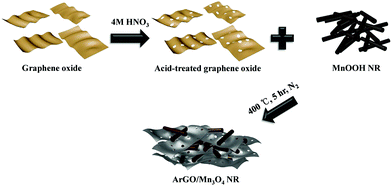
The effect of the acid-treated reduced graphene oxide on the electrochemical Li-storage properties of Mn3O4, however, has been rarely reported. In this work, we demonstrate the preparation of ArGO/Mn3O4 nanocomposites by simple mixing and thermal treatment (Scheme 1). Mn3O4 NR in the nanocomposites has a high aspect ratio and is homogeneously distributed between ArGO. This structure is effective to improve electrochemical performance due to the presence of various new pores between Mn3O4 NR and ArGO to provide open channels and pathways for Li ions. As a consequence, ArGO/Mn3O4 nanocomposites exhibits a high reversible capacity and cycling stability. The ArGO/Mn3O4 nanocomposites is expected to present obviously improved electrochemical properties compared with bare oxides and reduced graphene oxide-wrapped manganese oxide nanorods.
Experimental section
Preparation of graphene oxide and acid-treated graphene oxide
The modified Hummers' method was used to synthesize graphene oxide (GO) from graphite powder (<20 micron, Aldrich).38,39 The general synthetic procedure of GO consisted of pre-oxidation and oxidation. In the pre-oxidation step, 3 g of graphite in 80 mL of sulfuric acid (H2SO4, 95–98%, Aldrich) was mixed with 2.5 g of potassium persulfate (K2S2O8, 98.0%, SAMCHUN) and phosphorus pentoxide (P2O5, 97.0%, Aldrich). This solution was stirred and heated at 95 °C for 5 h. After the solution is naturally cooled down, it was vacuum-filtered and washed with DI water several times and freeze-dried overnight. In the oxidation step, 15 g of potassium permanganate (KMnO4, 99.3%, Aldrich) was slowly added to 120 mL of sulfuric acid solution with the obtained powders while the acid solution was in an ice bath. After the solution was reacted at 80 °C for 4 h, hydrogen peroxide (H2O2, 30.0–35.5%) was added to it. The color of the solution was instantly changed from dark brown to yellow. Lastly, the mixture solution was vacuum-filtered, washed and rinsed with diluted HCl solution (1![[thin space (1/6-em)]](https://www.rsc.org/images/entities/char_2009.gif) :
:![[thin space (1/6-em)]](https://www.rsc.org/images/entities/char_2009.gif) 10 volume ratio) and DI water to remove impurities and neutralize, followed by freeze-drying for 24 h. Acid-treated graphene oxide (AGO) was synthesized by using the process developed by Shi's group.40 Typically, 250 mg of GO was immersed in 250 mL of nitric acid solution (4 M) and refluxed at 100 °C for 1 hour. The resulting solution was washed several times with DI water to neutralize, and then it was freeze-dried.
10 volume ratio) and DI water to remove impurities and neutralize, followed by freeze-drying for 24 h. Acid-treated graphene oxide (AGO) was synthesized by using the process developed by Shi's group.40 Typically, 250 mg of GO was immersed in 250 mL of nitric acid solution (4 M) and refluxed at 100 °C for 1 hour. The resulting solution was washed several times with DI water to neutralize, and then it was freeze-dried.
Synthesis of MnOOH nanorod
MnOOH nanorods were prepared by a hydrothermal method.41 KMnO4, polyethylene glycol 400 (H(OCH2CH2)nOH, PEG-400, SAMCHUN) and DI water were prepared to obtain MnOOH NR. Typically, 0.3 g of KMnO4, 7.5 mL of PEG-400 and 60 mL of DI water were stirred for 30 min until the color of the solution was changed to purple brown. The mixture in a 100 mL Teflon-lined stainless steel autoclave was heated at 160 °C for 3 h in an electric oven. Finally, the brownish product was obtained and washed several times with DI water and ethanol.Fabrication of Mn3O4 NR, rGO/Mn3O4 NR and ArGO/Mn3O4 NR
Mn3O4 NR, rGO/Mn3O4 NR and ArGO/Mn3O4 NR were fabricated using a simple mixing and heat treatment. GO (or AGO) and MnOOH NR (3![[thin space (1/6-em)]](https://www.rsc.org/images/entities/char_2009.gif) :
:![[thin space (1/6-em)]](https://www.rsc.org/images/entities/char_2009.gif) 1 weight ratio) were homogeneously dispersed in DI water using sonication for 30 min followed by drying at 60 °C in an electric oven. The bare and mixed powders were heated in a tube furnace at 400 °C for 5 h under N2 atmosphere.
1 weight ratio) were homogeneously dispersed in DI water using sonication for 30 min followed by drying at 60 °C in an electric oven. The bare and mixed powders were heated in a tube furnace at 400 °C for 5 h under N2 atmosphere.
Material characterization
High-resolution transmission electron microscopy (HR-TEM, JEOL JEM 2100F) was performed to characterize the morphologies at an accelerating voltage of 200 kV. Field-emission scanning electron microscopy (FE-SEM, Hitachi S-4800) was used to examine the surfaces at an accelerating voltage of 0.5–30 kV. X-ray diffraction patterns of the samples were measured on an X-ray diffractometer (XRD, BRUKER D8 Advance) with Cu Kα radiation (α = 1.54 Å) at a scan rate of 2° min−1. Brunauer–Emmett–Teller (BET) specific surface areas (SSA) and pore-size distribution were calculated by N2 absorption/desorption isotherms on a BELSORP apparatus and Barrett–Joyner–Halenda (BJH) method, respectively.Electrochemical measurements
CR2016-type coin cells were assembled in an Ar-filled glovebox and tested for the electrochemical performance. The electrolyte was 1 M LiPF6 solution in a mixture of ethylene carbonate and dimethyl carbonate (1![[thin space (1/6-em)]](https://www.rsc.org/images/entities/char_2009.gif) :
:![[thin space (1/6-em)]](https://www.rsc.org/images/entities/char_2009.gif) 1 volume ratio). The working electrode was fabricated by mixing 70 wt% of active material (samples), 10 wt% of binder (PVDF) and 20 wt% of conductive carbon (Super P). These materials were mixed with the n-methyl-2-pyrrolidinone (NMP) and coated onto the Cu foil by a doctor blade. After drying at 60 °C in a vacuum oven for 2 h, the coated foil was compressed and cut into circular electrodes. Electrodes were dried overnight at 120 °C in a vacuum oven and transferred to an Ar-filled glove box. All the cells were galvanostatically tested at 200 mA g−1 between 0.01 and 3.0 V versus Li/Li+ (WBCS3000 cycler system, Wonatech, Korea). Cyclic voltammetry (CV) tests were also conducted at a scan rate of 0.1 mV s−1 between 0.01 and 3.0 V.
1 volume ratio). The working electrode was fabricated by mixing 70 wt% of active material (samples), 10 wt% of binder (PVDF) and 20 wt% of conductive carbon (Super P). These materials were mixed with the n-methyl-2-pyrrolidinone (NMP) and coated onto the Cu foil by a doctor blade. After drying at 60 °C in a vacuum oven for 2 h, the coated foil was compressed and cut into circular electrodes. Electrodes were dried overnight at 120 °C in a vacuum oven and transferred to an Ar-filled glove box. All the cells were galvanostatically tested at 200 mA g−1 between 0.01 and 3.0 V versus Li/Li+ (WBCS3000 cycler system, Wonatech, Korea). Cyclic voltammetry (CV) tests were also conducted at a scan rate of 0.1 mV s−1 between 0.01 and 3.0 V.
Results and discussion
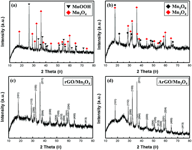
Fig. 1 shows the XRD patterns of MnOOH, Mn3O4, rGO/Mn3O4 and ArGO/Mn3O4 NR. The diffraction peaks of MnOOH NR can be indexed to a mixture of γ-MnOOH and Mn3O4. The results indicate that MnOOH NR is comprised of predominant γ-MnOOH and some Mn3O4. In the case of Mn3O4 NR, it consists of two phases as Mn3O4 and Mn5O8 indicating that the only MnOOH NR without GO or AGO is not completely reduced to Mn3O4 NR. On the other hand, the XRD peaks of rGO/Mn3O4 and ArGO/Mn3O4 nanocomposites match well to Mn3O4 hausmannite (JCPDS no. 24-0734). The diffraction peaks at 18.0°, 28.9°, 31.0°, 32.3°, 36.1° and 38.1° can be assigned to (101), (112), (200), (103), (211) and (004) planes of the tetragonal Mn3O4. As observed, the peaks of rGO and ArGO is not distinguished due to a lower content and intensity than those of Mn3O4 NRs. It can be reasonably deduced from the results that MnOOH NR including GO and AGO is more completely transformed to Mn3O4 NR.Fig. 2 presents the nitrogen adsorption/desorption isotherms and pore-size distribution of Mn3O4, rGO/Mn3O4 and ArGO/Mn3O4 NR. As shown in Fig. 2a, the isotherm of the ArGO/Mn3O4 NR nanocomposite was classified as type IV with an H3 hysteresis loop. ArGO/Mn3O4 NR exhibits a higher SSA than bare Mn3O4 and rGO/Mn3O4 NR because of the restrained aggregation of the nanorods and the introduction of acid-treated graphene nanosheet with a relatively large SSA. According to BJH data, the pore-size distribution and pore volume for ArGO/Mn3O4 NR are much higher than those for bare Mn3O4 and rGO/Mn3O4 NR. It is believed that ArGO is contributed to SSA and pore volume.
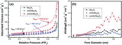 | ||
| Fig. 2 (a) Nitrogen adsorption/desorption isotherms and (b) pore-size distribution of Mn3O4 NR, rGO/Mn3O4 and ArGO/Mn3O4. | ||
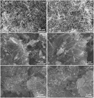
Fig. 3 displays SEM images of MnOOH, Mn3O4, rGO/Mn3O4 and ArGO/Mn3O4 NR. It demonstrates that MnOOH NR was transformed to Mn3O4 NR without any deformation during heat treatment. After AGO (or GO) and MnOOH NR were reduced, a ArGO (or rGO)/Mn3O4 sandwich-like structure was finally formed due to the restacking of the hydrophobic graphene nanosheet in Fig. 3c–f. This sandwich-like structure acts as a strain buffer for volume changes of Mn3O4 NR during the electrochemical reaction.42 In addition, the 1D structure of the nanorods provides a short diffusion length for Li-ion and electron transport along the 1D direction. Through the transparent rGO and ArGO, it is clear that Mn3O4 NR is confined in between graphene nanosheets, which provide the pathway and open channel for Li-ions and electrons, respectively. A large contact interface between electrode and electrolyte is also formed in this structure. Furthermore, Fig. 3c–f clearly indicates that Mn3O4 NR in the nanocomposite is uniformly distributed and continuously interconnected with rGO and ArGO. As a consequence of the ArGO (rGO)/Mn3O4 NR structure, it is anticipated that the electrolyte wettability over the entire nanocomposite and an effective diffusion for lithium ions and electrons is favorable. The morphology of the ArGO/Mn3O4 NR after 100 cycles was also characterized by SEM as shown in Fig. S1.† Mn3O4 nanorods still retains their 1D structure and SEI around them is observed. It confirms that ArGO nanosheets function as buffer layers to prevent the volume change of Mn3O4 NR.
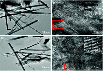
The crystalline structure and morphology of Mn3O4, rGO/Mn3O4 and ArGO/Mn3O4 NR were further studied by TEM and HR-TEM, as shown in Fig. 4. Without any structural variation, Mn3O4 NR (Fig. 4a) was formed after heat treatment, which is well matched with SEM results (Fig. 3a and b). In HR-TEM image of rGO/Mn3O4 and ArGO/Mn3O4 NR (the inset of Fig. 4d and f), Mn3O4 NR clearly have crystal lattice fringes of 0.31 and 0.27 nm, corresponding to the (112) and (103) planes, respectively.
Cyclic voltammetry (CV) tests were performed at a scan rate of 0.1 mV s−1 between 0.01 and 3 V to understand the redox reactions to Mn3O4 NR, rGO/Mn3O4 NR and ArGO/Mn3O4 NR as anode materials. The 1st, 2nd, 5th and 10th of CV curves for all electrodes are presented in the Fig. 5a, c and e. In the first cycle of the Mn3O4 NR electrode, a broad cathodic peak in the range of 0.5–1.9 V was observed and disappeared in the following cycles, which is ascribed to the formation of solid electrolyte interfaces (SEI) due to the electrolyte decomposition43 and the reduction of Mn3O4 (Mn3+) to MnO (Mn2+).16 In addition, the strong cathodic peak centered at 0.035 V is attributed to the reduction of MnO (Mn2+) to Mn (Mn0). After the first cycle, the reduction peak shifts from 0.035 to ca. 0.35 V because of the structural transformations during the first discharge.13,44–47 The anodic peak at 1.3 V corresponds to the oxidation of Mn to MnO.16 For the Mn3O4 NR electrode, this peak intensity decreases drastically which means the poor reversibility. As shown in the Fig. 5c, the CV curve for the rGO/Mn3O4 demonstrates the effect of reduced graphene oxides when Mn3O4 NR is mixed with rGO. Unlike the Mn3O4 electrode, the reversible capacity of the rGO/Mn3O4 electrode is pronouncedly enhanced. In the case of the ArGO/Mn3O4 electrode, there is another anodic peak at 2.34 V which is related with the further oxidation of MnO to Mn3O4.14,15,17,19,25,48,49 Furthermore, the cathodic peak at 1.65 V is clearly observed and associated with the reduction of Mn3O4 to MnO. It is anticipated that lithium ions may easily pass through graphene sheets without detouring. As a result of the CV curves, ArGO/Mn3O4 electrode displays a higher reversible capacity than Mn3O4 and rGO/Mn3O4 electrodes. Based on the CV analyses and the previous studies,50 the mechanism for the electrochemical conversion reaction between Li and Mn3O4 can be expressed by the following equation:
| Mn3O4 + 8Li+ + 8e− ↔ 3Mn + 4Li2O |
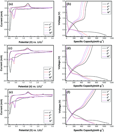 | ||
| Fig. 5 Cyclic voltammograms and charge–discharge profiles of (a, b) Mn3O4, (c, d) rGO/Mn3O4 and (e, f) ArGO/Mn3O4 NR. | ||
Fig. 5b, d and f shows the 1st, 2nd, 5th and 10th charge–discharge curves for all electrodes at a current density of 200 mA g−1 between 0.01 and 3 V. The curves are well-matched with the previous reports on12,15,16,24–27 the charge–discharge trend of Mn3O4 anodes. During the first discharge, the voltage plateau at 1.25 V is sloping down to 0.27 V, which is mainly attributed to the SEI formation and the initial reduction of Mn3O4 to MnO.15,25 The long voltage plateau from 0.27 V to 0.01 V indicates that MnO is further reduced to Mn.13,15 After the first cycle, the plateau at 0.27 V moves up to 0.45 V, which implies that lithium ions can readily react with MnO in the following cycles. On the other hand, the voltage plateau at 1.25 V results from the oxidation of Mn to MnO while the electrodes are charging.15
Mn3O4, rGO/Mn3O4 and ArGO/Mn3O4 electrodes deliver a first discharge capacity of 1060, 1100 and 1130 mA h g−1 and then a reversible capacity of 556, 695 and 778 mA h g−1, respectively. The ArGO/Mn3O4 electrode exhibits a lower initial irreversible capacity of 32% than those of 48 and 37% for Mn3O4 and rGO/Mn3O4 electrodes, respectively. The capacity loss for the first cycle is mainly due to the SEI formation by the decomposition of electrolyte and the large volume change which is the common phenomenon relating to the conversion reaction for anode materials. Coulombic efficiency (CE) increases to 98% after 3 cycles. The reversible capacity reaches to 749 mA h g−1 after 100 cycles, higher than other anode materials.
Among all electrodes, the ArGO/Mn3O4 electrode presents the most excellent reversibility because acid-treated reduced graphene oxides have the performance of the electrode improved. Consequently, the ArGO/Mn3O4 electrode has more stable and reversible charge–discharge process than other electrodes due to acid treatment of graphene oxide, which may promote the transportation for lithium ions and electrons through ArGO sheets.
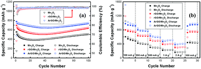
The cycle performance tests of electrodes were performed at a current density of 200 mA g−1 and the results were given in Fig. 6a. The initial charge capacity is 778 mA h g−1, and thereafter, the capacity decreases gradually. However, it is interesting that a gradual increase of capacity is also observed after the capacity reaches a minimum capacity. A high capacity of 749 mA h g−1 is achieved after 100 cycles. This capacity variation has been reported on many transitional metal oxides, particularly nanostructured MnxOy.51–53 Lowe and co-workers proposed that the extra capacity may be contributed to a capacitive-like charge storage.54 Yonekura et al. suggested that the increasing capacity was caused by the degradation of electrolyte.55 This phenomenon, proposed by J. M. Tarascon, might be related to the reversible growth of a polymeric gel-like film catalyzed by 3d metals.56 The capacity increases that comes from activation of electrode materials could be another possibility. In other words, small nanoparticles not only increase the surface area but also active sites for lithium storage. The polymeric gel-like SEI layer which can improve the mechanical cohesion among the active materials without hindering the ion transfer is formed by the electrolyte decomposition.
The rate performance of bare Mn3O4, rGO/Mn3O4 and ArGO/Mn3O4 nanocomposites from 100 to 2000 mA g−1 is shown in Fig. 6b. The ArGO/Mn3O4 electrode delivers a high capacity of 948, 778, 597, 509, and 412 mA h g−1 at different current densities of 100, 200, 500, 1000, and 2000 mA g−1, respectively. When the current density returned to 100 mA g−1, the discharge capacity of the ArGO/Mn3O4 electrode remarkably recovered to 802 mA h g−1. This performance presents that a high current density doesn't affect the ArGO/Mn3O4 electrode.
Conclusions
In this research, a simple and two-step process such as mixing and heat treatment was applied to fabricating the ArGO/Mn3O4 NR nanocomposite. Mn3O4 NR between ArGO layers is homogeneously dispersed, thus preventing aggregation of nanorods. The nanocomposite structure of ArGO and Mn3O4 NR not only forms large contact areas between electrolyte and electrode but also provide the effective diffusion pathways for Li-ions and electrons. As a result, the ArGO/Mn3O4 NR electrode delivers reversible capacities of 778 and 412 mA h g−1 at 200 and 2000 mA g−1, respectively, which are higher than those of bare Mn3O4 NR and rGO/Mn3O4 NR. It is expecting that ArGO/other metal oxides nanocomposites will be developed to improve the anode performance for energy storage devices.Acknowledgements
This work was supported by the Center for Integrated Smart Sensors funded by the Ministry of Science, ICT and Future Planning, Republic of Korea, as Global Frontier Project (CISS-012M3A6A6054186) and by Basic Science Research Program through the National Research Foundation of Korea (NRF) funded by the Ministry of Education (2015R1D1A1A01060398).Notes and references
- M. S. Whittingham, Chem. Rev., 2004, 104, 4271 CrossRef CAS PubMed.
- M. Armand and J. M. Tarascon, Nature, 2008, 458, 652 CrossRef PubMed.
- J. M. Tarascon and M. Armand, Nature, 2001, 414, 359 CrossRef CAS PubMed.
- P. G. Bruce, B. Scrosati and J. M. Tarascon, Angew. Chem., Int. Ed., 2008, 47, 2930 CrossRef CAS PubMed.
- S. Goriparti, E. Miele, F. De Angelis, E. Di Fabrizio, R. Proietti Zaccaria and C. Capiglia, J. Power Sources, 2014, 257, 421 CrossRef CAS.
- B. Dunn, H. Kamath and J. M. Tarascon, Science, 2011, 334, 928 CrossRef CAS PubMed.
- N. S. Choi, Z. Chen, S. A. Freunberger, X. Ji, Y. K. Sun, K. Amine, G. Yushin, L. F. Nazar, J. Cho and P. G. Bruce, Angew. Chem., Int. Ed., 2012, 51, 9994 CrossRef CAS PubMed.
- M. G. Kim and J. Cho, Adv. Funct. Mater., 2009, 19, 1497 CrossRef CAS.
- M. M. Thackeray, S. D. Baker and J. Coetzer, Mater. Res. Bull., 1982, 17, 405 CrossRef CAS.
- M. M. Thackeray and J. Coetzer, Mater. Res. Bull., 1981, 16, 591 CrossRef CAS.
- T. Iijima, Y. Toyoguchi, J. Nishimura and H. Ogawa, J. Power Sources, 1980, 5, 99 CrossRef CAS.
- H. Wang, L. F. Cui, Y. Yang, H. S. Casalongue, J. T. Robinson, Y. Liang, Y. Cui and H. Dai, J. Am. Chem. Soc., 2010, 132, 13978 CrossRef CAS PubMed.
- J. Z. Wang, N. Du, H. Wu, H. Zhang, J. X. Yu and D. Yang, J. Power Sources, 2013, 222, 32 CrossRef CAS.
- C. J. Chae, J. H. Kim, J. M. Kim, Y. K. Sun and J. K. Lee, J. Mater. Chem., 2012, 22, 17870 RSC.
- J. Gao, M. A. Lowe and H. c. D. Abruña, Chem. Mater., 2011, 23, 3223 CrossRef CAS.
- Z. C. Bai, N. Fan, Z. C. Ju, C. L. Guo, Y. T. Qian, B. Tang and S. L. Xiong, J. Mater. Chem. A, 2013, 1, 10985 CAS.
- S. Z. Huang, J. Jin, Y. Cai, Y. Li, H. Y. Tan, H. E. Wang, G. Van Tendeloo and B. L. Su, Nanoscale, 2014, 6, 6819 RSC.
- Z. C. Bai, X. Y. Zhang, Y. W. Zhang, C. L. Guo and B. Tang, J. Mater. Chem. A, 2014, 2, 16755 CAS.
- G. Q. Jian, Y. H. Xu, L. C. Lai, C. S. Wang and M. R. Zachariah, J. Mater. Chem. A, 2014, 2, 4627 CAS.
- A. Ponrouch, P. L. Taberna, P. Simon and M. R. Palacín, Electrochim. Acta, 2012, 61, 13 CrossRef CAS.
- D. Pasero, N. Reeves and A. West, J. Power Sources, 2005, 141, 156 CrossRef CAS.
- Q. Fan and M. S. Whittingham, Electrochem. Solid-State Lett., 2007, 10, A48 CrossRef CAS.
- C. Wang, L. Yin, D. Xiang and Y. Qi, ACS Appl. Mater. Interfaces, 2012, 4, 1636 CAS.
- S. Y. Liu, J. Xie, Y. X. Zheng, G. S. Cao, T. J. Zhu and X. B. Zhao, Electrochim. Acta, 2012, 66, 271 CrossRef CAS.
- L. Li, Z. Guo, A. Du and H. Liu, J. Mater. Chem., 2012, 22, 3600 RSC.
- N. Lavoie, P. R. L. Malenfant, F. M. Courtel, Y. Abu-Lebdeh and I. J. Davidson, J. Power Sources, 2012, 213, 249 CrossRef CAS.
- Z. H. Wang, L. X. Yuan, Q. G. Shao, F. Huang and Y. H. Huang, Mater. Lett., 2012, 80, 110 CrossRef CAS.
- S. Luo, H. C. Wu, Y. Wu, K. L. Jiang, J. P. Wang and S. S. Fan, J. Power Sources, 2014, 249, 463 CrossRef CAS.
- A. K. Geim and K. S. Novoselov, Nat. Mater., 2007, 6, 183 CrossRef CAS PubMed.
- K. S. Novoselov, A. K. Geim, S. V. Morozov, D. Jiang, M. I. Katsnelson, I. V. Grigorieva, S. V. Dubonos and A. A. Firsov, Nature, 2005, 438, 197 CrossRef CAS PubMed.
- C. M. Chen, Q. Zhang, J. Q. Huang, W. Zhang, X. C. Zhao, C. H. Huang, F. Wei, Y. G. Yang, M. Z. Wang and D. S. Su, J. Mater. Chem., 2012, 22, 13947 RSC.
- H. Zhang, L. Gao and S. Yang, RSC Adv., 2015, 5, 43798 RSC.
- Y. Ren, J. Wang, X. Huang, B. Yang and J. Ding, RSC Adv., 2015, 5, 59208 RSC.
- I. Nam, N. D. Kim, G.-P. Kim, J. Park and J. Yi, J. Power Sources, 2013, 244, 56 CrossRef CAS.
- D. K. Kim, P. Muralidharan, H. W. Lee and R. Ruffo, Nano Lett., 2008, 8, 3948 CrossRef CAS PubMed.
- X. Zhao, C. M. Hayner, M. C. Kung and H. H. Kung, ACS Nano, 2011, 5, 8739 CrossRef CAS PubMed.
- N. Wang, J. Yue, L. Chen, Y. Qian and J. Yang, ACS Appl. Mater. Interfaces, 2015, 7, 10348 CAS.
- W. S. Hummers and R. E. Offeman, J. Am. Chem. Soc., 1958, 80, 1339 CrossRef CAS.
- N. I. Kovtyukhova, P. J. Ollivier, B. R. Martin, T. E. Mallouk, S. A. Chizhik, E. V. Buzaneva and A. D. Gorchinskiy, Chem. Mater., 1999, 11, 771 CrossRef CAS.
- X. Wang, L. Jiao, K. Sheng, C. Li, L. Dai and G. Shi, Sci. Rep., 2013, 3, 1996 CrossRef PubMed.
- Z. Bai, N. Fan, Z. Ju, C. Sun and Y. Qian, Mater. Lett., 2012, 76, 124 CrossRef CAS.
- J. Su, M. Cao, L. Ren and C. Hu, J. Phys. Chem. C, 2011, 115, 14469 CAS.
- S. Grugeon, S. Laruelle, R. Herrera Urbina, L. Dupont, P. Poizot and J. M. Tarascon, J. Electrochem. Soc., 2001, 148, A285 CrossRef CAS.
- X. Li, X. Meng, J. Liu, D. Geng, Y. Zhang, M. N. Banis, Y. Li, J. Yang, R. Li, X. Sun, M. Cai and M. W. Verbrugge, Adv. Funct. Mater., 2012, 22, 1647 CrossRef CAS.
- C. Wang, D. Wang, Q. Wang and H. Chen, J. Power Sources, 2010, 195, 7432 CrossRef CAS.
- X. Wang, X. Li, X. Sun, F. Li, Q. Liu, Q. Wang and D. He, J. Mater. Chem., 2011, 21, 3571 RSC.
- J. Guo, Q. Liu, C. Wang and M. R. Zachariah, Adv. Funct. Mater., 2012, 22, 803 CrossRef CAS.
- H. Kim, S. W. Kim, J. Hong, Y. U. Park and K. Kang, J. Mater. Res., 2011, 26, 2665 CrossRef CAS.
- L. Wang, Y. Li, Z. Han, L. Chen, B. Qian, X. Jiang, J. Pinto and G. Yang, J. Mater. Chem. A, 2013, 1, 8385 CAS.
- J. F. M. Oudenhoven, L. Baggetto and P. H. L. Notten, Adv. Energy Mater., 2011, 1, 10 CrossRef CAS.
- L. Li, C. Nan, J. Lu, Q. Peng and Y. Li, Chem. Commun., 2012, 48, 6945 RSC.
- M. Kundu, C. C. Ng, D. Y. Petrovykh and L. Liu, Chem. Commun., 2013, 49, 8459 RSC.
- Q. Hao, J. Wang and C. Xu, J. Mater. Chem. A, 2014, 2, 87 CAS.
- M. A. Lowe, J. Gao and H. D. Abruña, J. Mater. Chem. A, 2013, 1, 2094 CAS.
- D. Yonekura, E. Iwama, N. Ota, M. Muramatsu, M. Saito, Y. Orikasa, W. Naoi and K. Naoi, Phys. Chem. Chem. Phys., 2014, 16, 6027 RSC.
- S. Grugeon, S. Laruelle, L. Dupont and J. M. Tarascon, Solid State Sci., 2003, 5, 895 CrossRef CAS.
Footnote |
| † Electronic supplementary information (ESI) available. See DOI: 10.1039/c7ra06396b |
| This journal is © The Royal Society of Chemistry 2017 |

