
 Open Access Article
 This Open Access Article is licensed under a
 Creative Commons Attribution 3.0 Unported Licence
Hierarchical porous graphitic carbon for high-performance supercapacitors at high temperature†
Chong Chena,
Dengfeng Yub,
Gongyuan Zhaoa,
Lei Suna,
Yinyong Sun a,
Kunyue Lenga,
Miao Yu*a and
Ye Sun*b
a,
Kunyue Lenga,
Miao Yu*a and
Ye Sun*b
aSchool of Chemistry and Chemical Engineering, Harbin Institute of Technology, Harbin 150001, China. E-mail: miaoyu_che@hit.edu.cn
bCondensed Matter Science and Technology Institute, Harbin Institute of Technology, Harbin 150001, China. E-mail: sunye@hit.edu.cn
First published on 10th July 2017
Abstract
Developing supercapacitors with high energy density without sacrificing the power density and cycle life has attracted enormous attention. Hierarchical porous graphitic carbons (HPGCs) have been demonstrated to be promising candidates. However, the complicated, energy-intensive synthesis and the difficult post-treatment for the reported synthetic HPGCs have confined the potential for large-scale production and practical applications. In this work, HPGCs have been fabricated by a one-step metallothermic reaction, using magnesium, urea, and zinc acetate dehydrate, showing a distinct hierarchical porous structure with graphitic domains. The assembled supercapacitors exhibit excellent performance at 150 °C, resulting in an energy density of 16 W h kg−1 (with a power density of 500 W kg−1). Moreover, the HPGC shows a high cycling stability (5% loss after 30![[thin space (1/6-em)]](https://www.rsc.org/images/entities/char_2009.gif) 000 cycles), and ultrahigh capacitance retention, i.e. 70% at 5 A g−1 and 62% at 10 A g−1 using EMIMBF4 electrolyte, and 70% at 400 mV s−1 and 77% at 20 A g−1 using 6 mol L−1 KOH electrolyte. Most importantly, the universality of this new metallothermic method of HPGC fabrication has been demonstrated by replacing urea with other chemical substances. Such a facile synthesis may have provided a fresh route to produce HPGCs with excellent supercapacitive performance.
000 cycles), and ultrahigh capacitance retention, i.e. 70% at 5 A g−1 and 62% at 10 A g−1 using EMIMBF4 electrolyte, and 70% at 400 mV s−1 and 77% at 20 A g−1 using 6 mol L−1 KOH electrolyte. Most importantly, the universality of this new metallothermic method of HPGC fabrication has been demonstrated by replacing urea with other chemical substances. Such a facile synthesis may have provided a fresh route to produce HPGCs with excellent supercapacitive performance.
1 Introduction
Over recent decades, sustainable energies and energy storage have never failed to attract attention, due to the fossil fuel crisis, ecological deterioration and the enormous demand of modern economic developments. Superior to lithium-ion batteries which have successfully occupied the market, supercapacitors have been recognized as highly promising energy storage devices due to their high power density, high charging/discharging rate, long-term cycling life and high safety.1 However, the energy density of commercially-available supercapacitors, which is an order of magnitude lower than that of lithium-ion batteries, still does not meet the ever-growing need for high-performance energy storage.2 Therefore, developing supercapacitors with high energy density without sacrificing the power density and cycle life has become essential and fascinating.Given that the energy density of a supercapacitor is proportional to the total capacitance and the square of the operating voltage, significant efforts have been devoted to produce electrode materials with higher capacitances and new electrolytes with higher maximum operating voltages.3,4 Among numerous electrode materials, porous carbon materials have stimulated tremendous interest and investigated extensively, because of their high specific surface area (SSA), stable physicochemical properties, wide-ranging operating voltage and low cost.5–12 In particular, three-dimensional (3-D) hierarchical porous carbons, combining macroporous cores, mesoporous walls, and micropores, have been demonstrated to be the most competent candidates, where the interconnected porous configuration can minimize diffusion pathways to the interior surfaces, decrease transport resistance of ions, increase the accessible and electroactive surface area for ion storage.10,13 In addition, a high electronic conductivity, which is mainly determined by the degree of crystallinity, is also essential for the capacitive performance of carbon electrode materials.14 It is known that, albeit inducing largely enhanced conductivity, a high crystallinity, i.e. graphitization, can seriously reduce the SSA.15 In this case, hierarchical porous graphitic carbon (HPGC) optimizing both SSA and conductivity is preferred with pronounced superiorities. So far, most of synthetic HPGCs were fabricated by adding catalyst precursors (such as nickel nitrate or ferric chloride) and/or adopting a high-temperature (>900 °C) carbonization. Apparently, such complicated and energy-intensive synthesis, and difficult post-treatment to remove the catalyst have confined the potential for large-scale production and practical applications.9–10,16–18 It is, therefore, paramount to develop a facile, low-cost, and universal method to fabricate HPGCs.
Ionic liquids (ILs) have emerged as promising electrolytes owing to their distinct advantages, including low vapor pressure, non-flammability, chemical and thermal stability, low toxicity and large electrochemical potential window.19 As a matter of fact, the low ionic conductivity and high viscosity of ILs at room temperature are detrimental.20 To overcome the drawbacks, one attempt is to dissolve ILs in organic solvents, e.g. acetonitrile, propylene carbonate (PC), etc., which however increases the volatility, flammability and toxicity of the electrolytes inevitably.21–22 For instance, given the boiling point of 80 °C and high flammability, the addition of acetonitrile can induce severe instability at a temperature higher than 100 °C.22 Another efficient and more reliable approach is by increasing working temperature.23 This is also beneficial for the devices operating at high temperatures, such as those applied in automotive, aerospace, solar/wind energy, and ultrahigh power electronics.24,25 Very recently, major progress has been accomplished on increasing the maximum operating temperature of supercapacitors.25–27 Li et al. reported that a maximum energy density of 50.1 W h kg−1, a capacitance of 160.3 F g−1 (at 0.1 A g−1) and 53.8% of the rate capability (at 1 A g−1) can be achieved by supercapacitors based on a 3-D hierarchical porous graphene/carbon composite at 100 °C.26 Kim et al. demonstrated that a maximum energy density of 11 W h kg−1, a capacitance of 160 F g−1 (at 0.5 A g−1) and 78% of the rate capability (at 10 A g−1) were obtained from a super-capacitors assembled using graphene oxide flexible films at 160 °C.25 Wang et al. reported a high capacitance of 165 F g−1 at 1.5 A g−1 and 104 F g−1 at 25 mV s−1 from supercapacitors using IL-based gel electrolytes at 200 °C.27 Although the capacitance mentioned look similar, those obtained at higher current densities indicate a better capacitive property since the specific capacitance normally suffers a large reduction at higher current densities due to the less time allowing for electrolyte ions diffusion.10 In another word, besides the maximum capacitance and energy density, a high capacitance retention at higher scan rate/current density is also rather crucial. Clearly, supercapacitors with a significant enhancement of capacitance, rate capability, capacitance retention and energy density would be much more preferred.
In this work, HPGCs have been fabricated by one-step metallothermic reaction, using magnesium (Mg), urea (U), and zinc acetate dehydrate (ZA), as the reductant, carbon source, and hard template/supplement carbon source, respectively (Fig. 1). The products possess a distinct hierarchical porous structure integrating interconnected macro-, meso- and micropores. Meanwhile, the HPGCs have graphitic domains to benefit the conductivity, with the graphitization degree tunable by the combination of the reactants. The supercapacitors assembled using the HPGCs as the electrode material and 1-ethyl-3-methylimidazolium tetrafluoroborate (EMIMBF4) as the electrolyte exhibited excellent performance at 150 °C, showing a specific capacitance of 115 F g−1 at a current density of 0.5 A g−1, an energy density as high as 16 W h kg−1 (with a power density of 500 W kg−1). Moreover, the HPGC shows a high cycling stability (1% loss after 10000 cycles), and ultrahigh capacitance retention, i.e. 70% at 5 A g−1 and 62% at 10 A g−1 using EMIMBF4 electrolyte, and 70% at 400 mV s−1 and 77% at 20 A g−1 using 6 mol L−1 KOH electrolyte. Most importantly, the universality of this new metallothermic method of HPGC fabrication has been demonstrated by replacing urea with other chemical substances, including glycine, polyvinylpyrrolidone and hexamethylene-tetramine. Such a facile, low cost and energy-saving synthesis together with the easy post-treatment may have provided a fresh route to produce HPGCs with excellent supercapacitive performance.
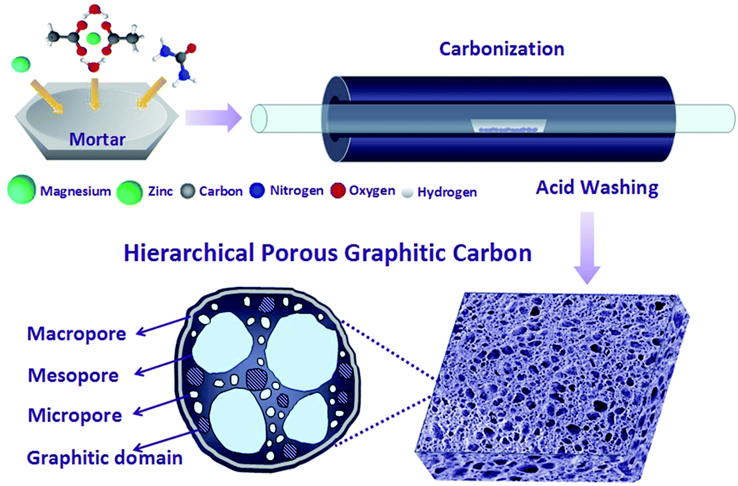 | ||
| Fig. 1 Schematic illustration of HPGCs synthesized by one-step metallothermic reaction. | ||
2 Experimental details
2.1 Synthesis of the HPGCs
The HPGCs were synthesized by one-step metallothermic reaction. In brief, magnesium (Mg, 6.0 g, 200 mesh), urea (CO(NH2)2, 2.0 g), and zinc acetate dehydrate (Zn(CH3COO)2·2H2O, 6.0 g) were mixed together, and placed in a corundum boat in a horizontal tube furnace. After flushing with Argon flow for 30 min, the furnace was heated to 700 °C at a rate of 5 °C min−1 and kept at the temperature for 2 h. The samples were collected, then immersed in 0.1 mol L−1 HCl aqueous solution for 12 h and repeatedly washed with deionized (DI) water. The final product (200 mg) was obtained after drying at 120 °C for 12 h.2.2 Instruments
The samples were characterized by TEM (FEI, Tecnai-G2-F30), XRD (PANalytical, X'Pert Pro, with Cu Ka radiation), Raman spectroscopy (Renishaw with an excitation at 532 nm), and XPS (ESCALAB, 250Xi). The SSA and pore size distribution were measured by nitrogen adsorption–desorption isotherms at 77.4 K (Quantachrome Autosorb-iQ) after vacuum drying at 200 °C for 30 h, and calculated by using a multi-point BET method to deduce the SSA and by using the quenched solid density functional theory method to deduce the pore size distribution and total pore volume.3 Results and discussion
3.1 Characterization of the carbon samples
To understand the formation mechanism and optimize the properties of the products, a series of carbon samples were fabricated by using different combination of Mg, U, and ZA at different mass ratios, including (1) the carbons produced by the Mg/U mixtures, denoted as ‘GC-nMg/U’, where n indicates the mass ratio of Mg:U; (2) those produced by the Mg/ZA mixtures, denoted as ‘GC-Mg/ZA’ (Mg:ZA = 1:1); (3) those produced by Mg/U/ZA mixtures, denoted as ‘HPGC-m’, where m indicates the mass ratio of ZA:U. Since ‘GC-3Mg/U’ showed the best electrochemical properties among all Mg/U samples in the pre-selection, Mg:U was kept as 3:1 for the fabrication of ‘HPGC-m’ samples.
All the samples obtained were first characterized by Raman spectroscopy (Fig. 2a), presenting three peaks in each spectrum, including the G-band at 1580 cm−1 attributed to the E2g vibration mode of sp2 hybridized carbon atoms of in-plain graphite, the D-band at 1340 cm−1 corresponding to the defects in the graphitic carbon, and the 2D band at 2680 cm−1 which is characteristic of GCs, indicating the graphitic nature of all the samples. According to the literature, the graphitization degree can be qualitatively evaluated by the intensity ratio between D- and G-band (ID/IG),28 and a higher ID/IG means a less graphitization. As shown in Fig. 2b, the varied values of ID/IG imply that the graphitization degree of the products can be modified by changing the combination of the reactants in the synthesis. It is noticeable that, ‘HPGC-3’ exhibited a higher ID/IG than all the other samples, together with the weakest 2D-band peak, revealing the presence of abundant defects in the graphitic domains. The crystallization nature of ‘GC-Mg/ZA’, ‘GC-3Mg/U’, and ‘HPGC-3’ were then characterized by X-ray diffraction (XRD). Consistently, while the sharp and strong peak at around 26° corresponding to the (002) graphitic structure15 indicate the high graphitization of ‘GC-3Mg/U’ and ‘GC-Mg/ZA’, the broad and weaker peak located in that range reveal the less crystallinity of ‘HPGC-3’ (Fig. 2c).
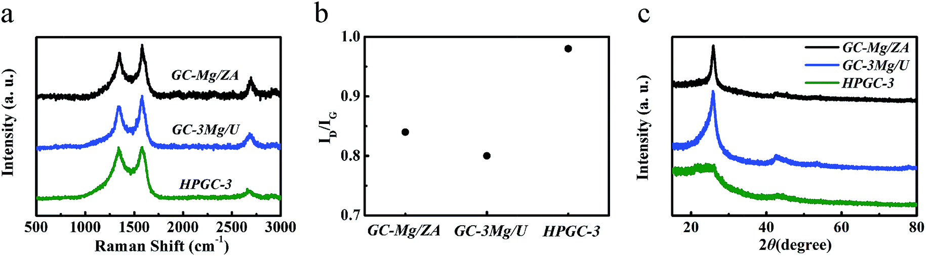 | ||
| Fig. 2 (a) Raman spectra and (b) the intensity ratio of D- and G-band (ID/IG) of ‘GC-Mg/ZA’, ‘GC-3Mg/U’, and ‘HPGC-3’. (c) XRD patterns of ‘GC-Mg/ZA’, ‘GC-3Mg/U’, and ‘HPGC-3’. | ||
The structure of the ‘GC-3Mg/U’ and ‘HPGC-3’ samples was further characterized by transmission electron microscopy (TEM) (Fig. 3). ‘GC-3Mg/U’ showed a porous structure (Fig. 3a). In good agreement with the XRD and Raman results, the high resolution (HR) image (Fig. 3b) in the inset revealed its good crystallization nature, showing a lattice spacing of ∼0.37 nm corresponding to the interlayer spacing of graphite (002).18 As comparison, ‘HPGC-3’ was more porous, showing a texture composed of much more pores with sizes in the range of 4–70 nm, i.e. macrospores (marked by the blue dashed line in Fig. 3c) and mesopores (circled by the green dashed contours in Fig. 3d). The HRTEM image (Fig. 3e) further revealed that high-density micropores (depicted by the green dashed contours, 1.5–2.0 nm) were distributed homogeneously throughout the walls of mesopores. Still, small graphitic domains with high crystallinity can be observed (Fig. 3f), showing a lattice spacing of ∼0.21 nm which is attributed to the d-spacing of graphene (100) planes.29
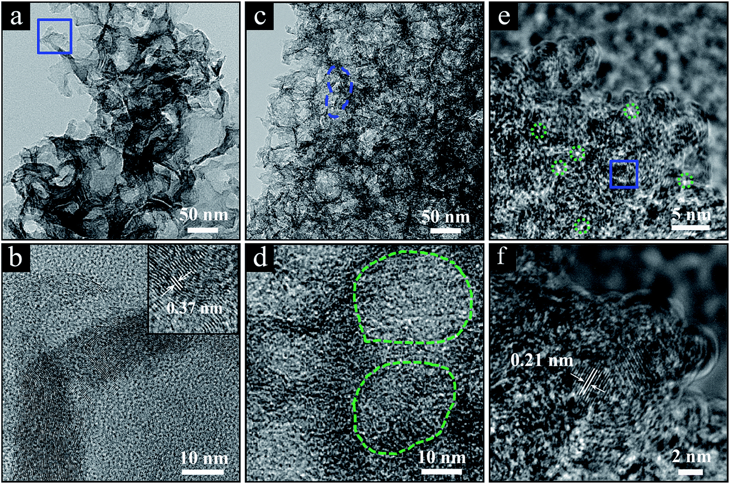 | ||
| Fig. 3 (a) TEM image of ‘GC-3Mg/U’ and (b) zoom-in image of the marked section in panel a with a high-resolution (HR) TEM image in the inset. (c and d) TEM images of ‘HPGC-3’, where typical macro- and mesopores are circled by the dashed lines in blue and green, respectively. (e) HRTEM image of ‘HPGC-3’ and (f) zoom-in image corresponding to the marked blue-square section in panel (e). The typical micro-pores are circled by the green dashed lines. | ||
The porosity nature of the ‘HPGC-3’ sample was further explored by the nitrogen adsorption–desorption isotherm. As shown in Fig. 4a, the isotherm was type I + IV according to IUPAC classification, showing multiple pore sizes ranging from micropores to mesopores. The nitrogen adsorption at low pressure region implies the presence of micropores. The adsorption–desorption hysteresis loop and the steep rise in adsorption at the relative pressure of >0.4 indicate a large amount of mesopores. The sharp increase at the high pressure region of the adsorption curve indicates the existence of macropores.17 The hierarchical porosity is in good accordance with the TEM results. Moreover, the BET SSA and total pore volume were calculated to be 765 m2 g−1 and 1.41 cm3 g−1, which were higher than those of the other samples (Fig. S1 ESI†). The sample was also analyzed by the pore size distribution using the density functional theory (DFT) method (Fig. 4b). Sharp and strong peaks at 2.0 and 4.7 nm together weaker ones located from 1.6 to 33.0 nm were observed, indicating the combination of micro- and mesopores in the ‘HPGC-3’ sample, together with macropores revealed by the isotherm.
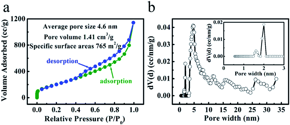 | ||
| Fig. 4 (a) Nitrogen adsorption–desorption isotherm and (b) pore size distribution of ‘HPGC-3’. | ||
The chemical composition of the ‘HPGC-3’ and ‘GC-3Mg/U’ samples were further investigated by X-ray photoelectron spectroscopy (XPS). The survey (Fig. 5a) showed C, O, and N content of 92.1, 7.2, and 0.7 wt%, respectively. As comparison, no N element was detected in the ‘GC-3Mg/U’ sample (Fig. S2 ESI†). The high-resolution C 1s spectrum (Fig. 5b) can be deconvoluted into four peaks centered at 284.8, 285.7, 286.6 and 290.3 eV, assigned to C![[double bond, length as m-dash]](https://www.rsc.org/images/entities/char_e001.gif) C/C–C, C–N, C–O, and O–CO, respectively.29,30 The O 1s spectrum (Fig. 5c) can be deconvoluted into two peaks located at 532.3 and 533.7 eV, corresponding to CO and O–CO groups respectively.31 The weak peak located at 400.1 eV (Fig. 5d) can be attributed to pyrrolic nitrogen (N-5).
C/C–C, C–N, C–O, and O–CO, respectively.29,30 The O 1s spectrum (Fig. 5c) can be deconvoluted into two peaks located at 532.3 and 533.7 eV, corresponding to CO and O–CO groups respectively.31 The weak peak located at 400.1 eV (Fig. 5d) can be attributed to pyrrolic nitrogen (N-5).
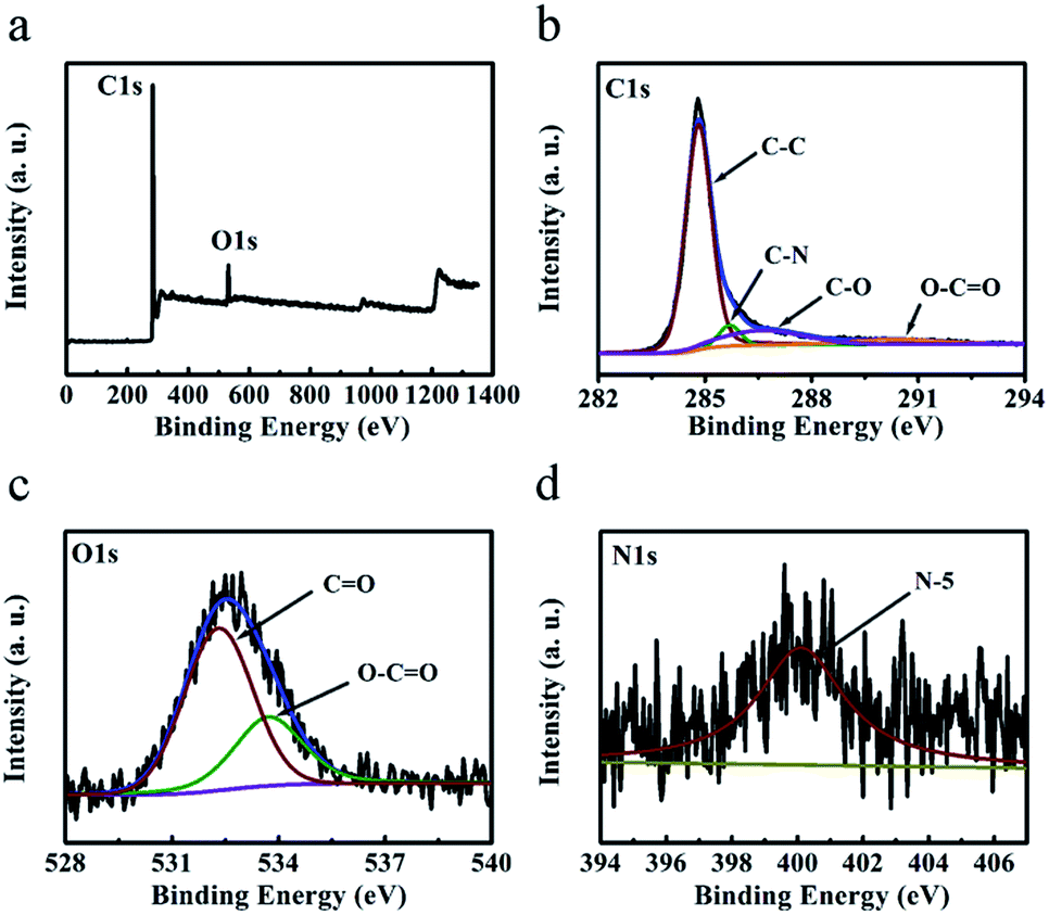 | ||
| Fig. 5 (a) XPS survey, (b) C 1s, (c) O 1s and (d) N 1s spectra of the ‘HPGC-3’ sample. | ||
Based on the Raman, XRD, TEM, XPS, the nitrogen adsorption–desorption isotherm and pore size distribution analysis of ‘HPGC-3’, we can conclude that this carbon material synthesized by the one-step metallothermic reaction using Mg/U/ZA was highly porous, showing a distinct hierarchical structure interconnected by micro-, meso- and macropores together with graphitic domains and doping of N and O. As well-demonstrated in the literature, the macropores can form the ion-buffering reservoirs to minimize the diffusion distances of ions to the interior surfaces of the electrode materials, while the mesoporous walls can facilitate low-resistant traverse for the ions and perform as the skeleton to avoid collapse, and the micropores can increase the ion-storage capability.10 In this way, the hierarchical porous structure can significantly increase the effective surface area hence the specific capacitance and energy density, meanwhile favor fast charge/discharge and high capacitance retention.32 Moreover, the small graphitic domains can enhance the electrical conductivity to further benefit its capacitive properties without compromising the SSA.33 In addition, the doping of heteroatoms, such as N and O, can enhance the wettability of carbon materials and generate pseudocapacitance in addition to the electrical double-layer capacitance (EDLC),34 hence to improve the supercapacitor performance significantly. Together with the high thermal and chemical stability of porous carbons, ‘HPGC-3’ may have promising potentials for high-performance supercapacitor, even applied under harsh conditions.
3.2 Reaction mechanism
To understand the reaction mechanism and the formation of the hierarchical porous carbons, we analyzed the XRD patterns of ‘HPGC-3’, ‘GC-3Mg/U’ and ‘GC-Mg/ZA’ before HCl treatment. As shown in Fig. 6, hexagonal Mg (JCPDS card no. 35-0821) and massive cubic MgO (JCPDS card no. 71-1176) were observed in all the samples together with a third component, hexagonal ZnO (JCPDS card no. 76-0704) for ‘HPGC-3’, traces of cubic Mg3N2 (JCPDS card no. 35-0778) and monoclinic Mg4Zn7 (JCPDS card no. 29-0878) for ‘GC-3Mg/U’ and ‘GC-Mg/ZA’, respectively. In the reaction, Mg was excess and it is not unreasonable to see unreacted Mg remaining. MgO was formed from the metallothermic reaction of Mg with CO2 derived from the thermal decomposition of U or/and ZA,35–37 and ZnO was also derived from decomposed ZA. Carbon was produced from the reduction of CO2 by Mg.38 To prove this point, a control experiment was performed by heating the U/ZA mixture under the same conditions as the synthesis. White power instead of black carbon was found in the corundum boat (Fig. S3 ESI†), and no carbon was obtained after HCl treatment. The different structures of the three samples were induced by the different combinations of the reactants. For ‘GC-3Mg/U’ and ‘GC-Mg/ZA’, the meso- and macropores were generated by etching the in situ formation of MgO in the carbon materials upon HCl washing. While for ‘HPGC-3’, both MgO and ZnO performed as hard template to form the meso- and macropores, and the micropore was induced by the evaporation of abundant volatile species, such as CO2, CO, H2O and N-containing gas during the pyrolysis process of urea and ZA. In the Mg/U/ZA system, ZA provided not only carbon resource additional to U but also a dual template with MgO.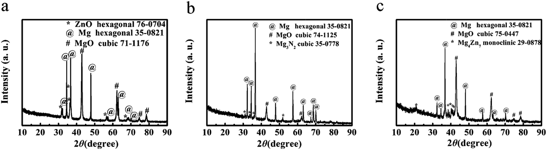 | ||
| Fig. 6 XRD patterns of (a) ‘HPGC-3’, (b) ‘GC-3Mg/U’ and (c) ‘GC-Mg/ZA’ before HCl treatment. | ||
3.3 Supercapacitive performance
To compare and evaluate the supercapacitive performance of all the samples, the cyclic voltammetry (CV) and galvanostatic charge–discharge curves of ‘GC-Mg/ZA’, ‘GC-nMg/U’, and ‘HPGC-3’ were attributed to its hierarchical porous structure and graphitic nature, as discussed above. It is worth emphasizing that the value of 320 F g−1 is higher than or comparable to that of previously fabricated hierarchical porous carbons (Table S1 ESI†). The performance of ‘HPGC-3’ was then further examined in a two-electrode coin-type system using the same electrolyte. As shown in Fig. 7a, the CV curves exhibited an ideal rectangular shape at all scan rates ranging from 5 to 400 mV s−1, revealing the dominant contribution and good nature of EDLC formed. In particular, the rectangular curve maintained at the highest scan rate of 400 mV s−1 directly revealed a quick ion transfer, which is exactly one of the pronounced advantages of the HPGCs. Moreover, the galvanostatic charge–discharge curves (Fig. 7b) exhibited a nearly triangular shape at all current density ranging from 1 to 20 A g−1, showing highly reversible charge–discharge behavior. It is worthy to mention that, for a great proportion of reported results so far, a steep decline normally occurs with increased scan rate or current density, due to the less time allowing for electrolyte ions diffusion. In many cases, albeit a relative high value achieved at a low current density/scan rate (e.g. 0.5 A g−1), only 30% or lower of the capacitance value can be maintained even at 10 A g−1. Encouragingly, ultrahigh capacitance retention was achieved from ‘HPGC-3’, i.e. 70% at a scan rate as high as 400 mV s−1 (Fig. 7c), and 77% at a current density as high as 20 A g−1 (Fig. 7d). This can be attributed to the hierarchical porosity and good electrical conductivity of the HPGC. As anticipated, the interconnected macro-, meso- and micropores can shorten ion diffusion distance and minimize ion transport resistance to induce the high-rate performance and the high capacitance retention. All these results confirm the excellent properties of ‘HPGC-3’ for high-rate operation.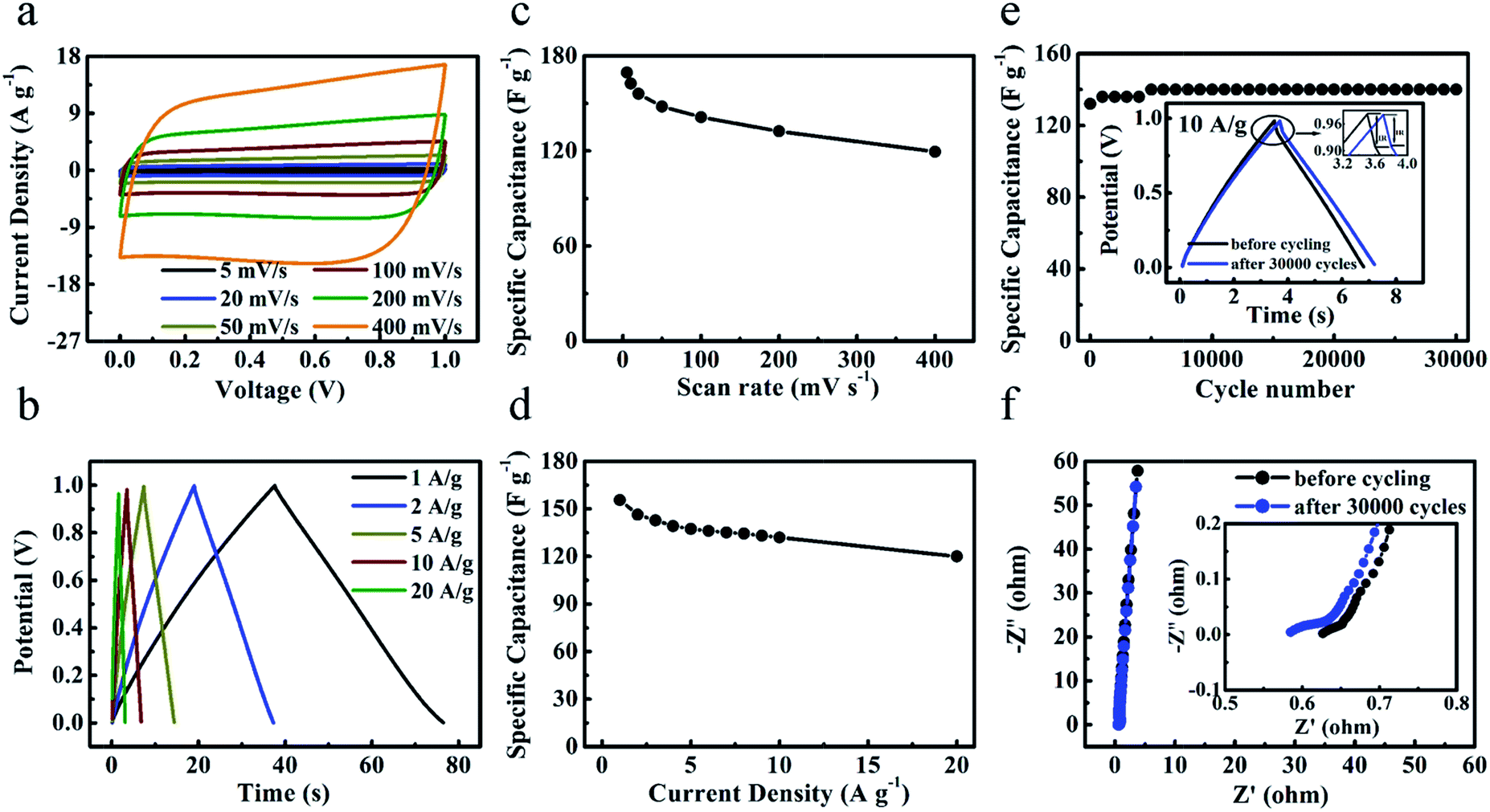 | ||
| Fig. 7 Electrochemical performance of ‘HPGC-3’ measured in a two-electrode system using the 6 M L−1 KOH aqueous solution as the electrolyte. (a) CV curves at different scan rates from 5 to 400 mV s−1. (b) Specific capacitances at various scan rates. (c) Galvanostatic charge–discharge curves at different current densities. (d) Gravimetric capacitances at different current densities. (e) Cycling stabilities measured at 20 A g−1, with the magnified galvanostatic charge–discharge curves before and after 30000 cycles in the inset. (f) Nyquist plots before/after 30000 cycles. | ||
Long-term cyclic stability is another important factor to evaluate the supercapacitive performance. As shown in Fig. 7e, the ‘HPGC-3’ based supercapacitor exhibited a quite high stability over 30000 cycles at the current density of 10 A g−1. Capacitance retention of 106% was achieved after the 30000 cycles, where the slight increase occurred during the initial 5000 cycles is likely attributed to the enhanced effectiveness of the electrode surfaces during charge–discharge process. The IR drop (voltage drop) was decreased after the 30000 cycles, as depicted in the insert of Fig. 7e, which indicates a lower overall internal resistance. The complex-plane Nyquist plot before/after 30000 cycles (Fig. 7f) both showed as a nearly vertical line, with a semicircle in the high-frequency region (the inset). The vertical lines at the low frequency region revealed the nearly ideal capacitive behavior without diffusion limitation, while the semicircle at the high frequency region reflected the charge transfer resistance.38 The equivalent series resistances (ESR) obtained by the x-intercept of the Nyquist plots was decreased from 0.63 to 0.59 Ω after the 30000 cycles, hence leading to the smaller IR drop.
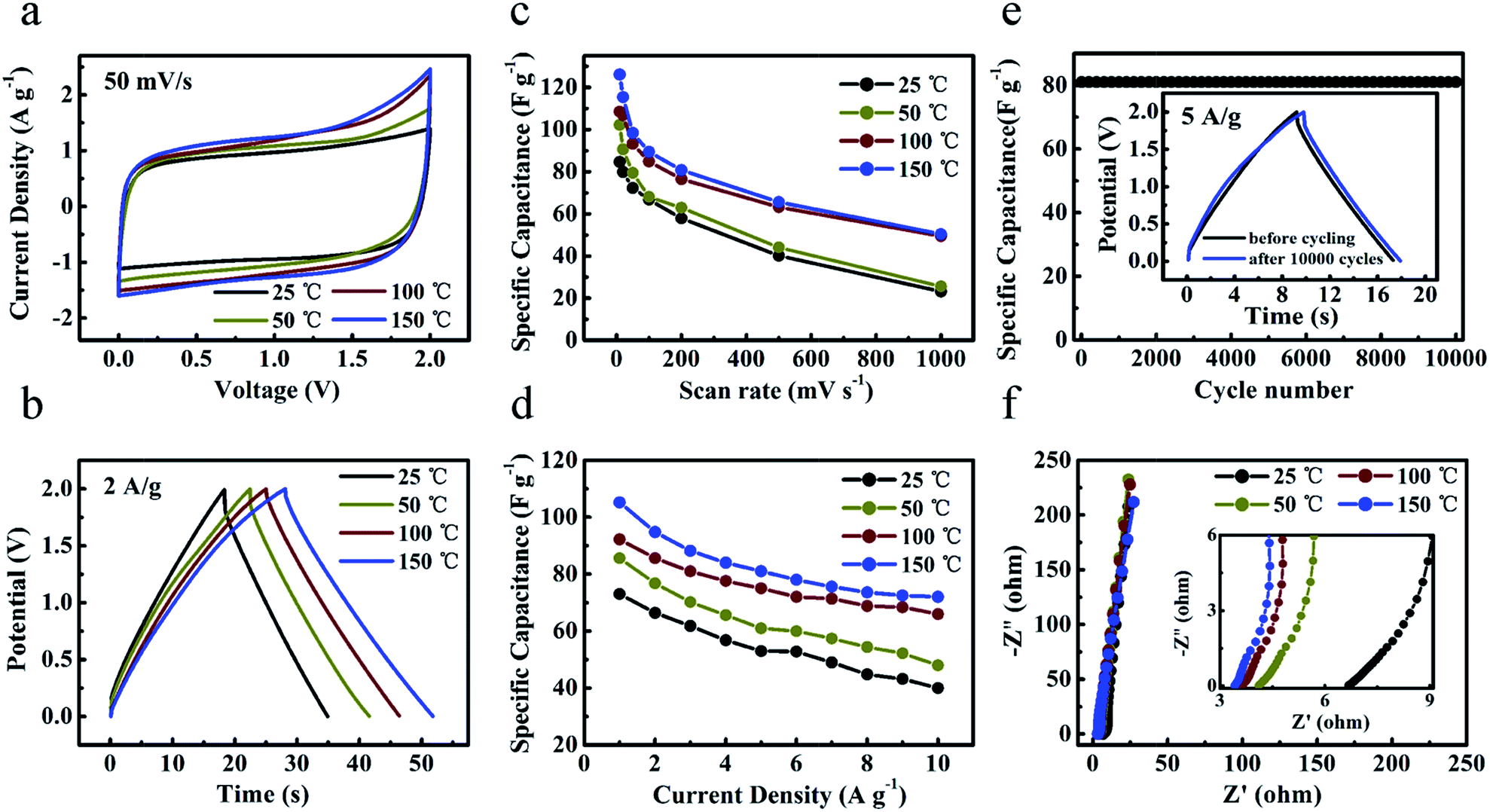
To explore the application potentials operating at high temperature, two-electrode coin-type ‘HPGC-3’-based super-capacitors were fabricated with a typical IL, i.e. EMIMBF4, as the electrolyte. The performance of the device was investigated by CV and galvanostatic charge–discharge at 25 °C, 50 °C, 100 °C, and 150 °C (Fig. 8a and b), respectively. The device can be operated at a wide voltage window range from 0 to 2 V. Both rectangular CV curves and symmetric triangular galvanostatic charge–discharge profiles revealed its good EDLC properties (Fig. S5 ESI†). Fig. 8c and d present the specific capacitances calculated from the CV and charge–discharge curves at different temperatures. Notably, both the specific capacitances and rate capability were largely enhanced at 100 °C and 150 °C (Fig. 8c), due to the enhanced ionic conductivity and lower viscous of ILs as well as the unique texture of the HPGC. For instance, the capacitance at 150 °C was increased to 2.1 folds as that at 25 °C when scanned at 1000 mV s−1. This phenomenon is consistent with the earlier reports.25,26 In addition, the capacitance retention was also raised largely. For example, the retention can be maintained to be ∼40% at a rather high scan rate of 1000 mV s−1. In the galvanostatic charge–discharge profiles, a capacitance of 115 F g−1 (at 0.5 A g−1) was achieved at 150 °C (Fig. 8d). More importantly, ultrahigh capacitance retention of 70% (at 5 A g−1) and 62% (at 10 A g−1) was achieved at this temperature. Meanwhile, after 10000 charge–discharge cycles at 5 A g−1 (Fig. 8e) and 150 °C, the specific capacitance was extremely steady over the cycling with only 1% loss. The nearly unchanged specific capacitance was also observed after 1500 charge–discharge cycles at 2 A g−1 and 150 °C (Fig. S6a ESI†). Furthermore, the stability upon repeated heating–cooling cycles was also investigated (Fig. S6b ESI†). It was found that the specific capacitance at 150 °C was not influenced by such cycling. And the samples after the cycling showed capacitance retention of 100% upon 500 charge–discharge cycles at 5 A g−1.
 | ||
| Fig. 8 Electrochemical performance of ‘HPGC-3’ in a two-electrode system using EMIMBF4 electrolyte at 25 °C, 50 °C, 100 °C, and 150 °C. (a) CV curves at 50 mV s−1 in a voltage window from 0 to 2 V. (b) Galvanostatic charge–discharge curves at 2 A g−1. (c) Volumetric capacitances at various scan rates. (d) Gravimetric capacitances at different current densities from 0.5 to 10 A g−1. (e) Cycling stabilities measured at 5 A g−1, with the magnified galvanostatic charge–discharge curves before and after 10000 cycles in the inset. (f) Nyquist plots with the magnified section in the inset. | ||
The frequency response of the ‘HPGC-3’-based super-capacitor was analyzed by electrochemical impedance spectroscopy, with the frequency range from 0.01 Hz to 100 kHz and amplitude of 5.0 mV (Fig. 8f). All Nyquist plots exhibited almost vertical lines at a low frequency region and no evident semicircle was observed in the high frequency region, indicating the nearly ideal capacitive behavior with low charge transfer resistance. As the temperature was increased from 25 to 150 °C, the ESR of the device was decreased from 6.7 to 3.4 Ω, consistent with the literature.39 The power and energy density of ‘HPGC-3’ can be easily deduced from the Ragone plots (Fig. S6c ESI†). An energy density as high as 16 W h kg−1 with a power density of 500 W kg−1 was achieved at 150 °C. Even when the power density was increased to 10000 W kg−1, a high energy density of 10 W h kg−1 can be still maintained.
Tandem ‘HPGC-3’-based supercapacitors assembled in series and in parallel configurations (Fig. 9a and b) were also examined at 150 °C. When two supercapacitors were connected in series, the voltage window was double as that of a single device, together with a similar discharge time at a given current (Fig. 9a and b). When two devices were in parallel, the discharge time was increased more than two times as that of a single device at the same current (Fig. 9a and b). Furthermore, a device of two ‘HPGC-3’-based supercapacitors assembled in series were used to power red LEDs (Fig. 9c, the Video was presented in the ESI†) and drive a small fan (Fig. 9d) at 150 °C, which directly demonstrated its excellent performance on energy storage.
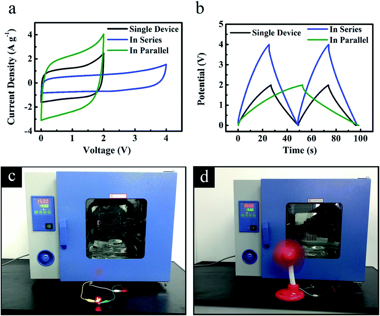 | ||
| Fig. 9 Electrochemical performance of the tandem ‘HPGC-3’-based two-electrode supercapacitors using EMIMBF4 electrolyte at an operation temperature of 150 °C. (a) CV curves at 50 mV s−1 and (b) galvanostatic charge–discharge curves at 2 A g−1. Digital photographs of (c) 3 LEDs and (d) a small fan powered by the tandem ‘HPGC-3’-based supercapacitors working at 150 °C. | ||
3.4 Universality of the metallothermic reaction on HPGC synthesis
As mentioned above, we develop a facile, low cost, energy-saving synthesis with easy post-treatment to produce HPGCs with high supercapacitive performance at high operating temperature. To prove the universality of this new method, we extended the one-step metallothermic reaction to other chemical substances by replacing urea. In brief, additional HPGCs were produced under the same experimental conditions as those for ‘HPGC-m’, by the combination of Mg and ZA with other chemicals instead of U, including glycine (NH2CH2COOH, G), polyvinylpyrrolidone ((C6H9NO)n, P) and hexamethylenetetramine (C6H12N4, H), at the mass ratio same as that of ‘HPGC-3’, denoted as ‘HPGC-3G’, ‘HPGC-3P’ and ‘HPGC-3H’, respectively. The hierarchical porous graphitic structure of all these samples were confirmed by both Raman spectroscopy and TEM images (Fig. 10). The supercapacitive performance of all samples were examined in a three-electrode system using 6 mol L−1 KOH aqueous solution as the electrolyte (Fig. S7 ESI†), showing good electrochemical performance in all cases.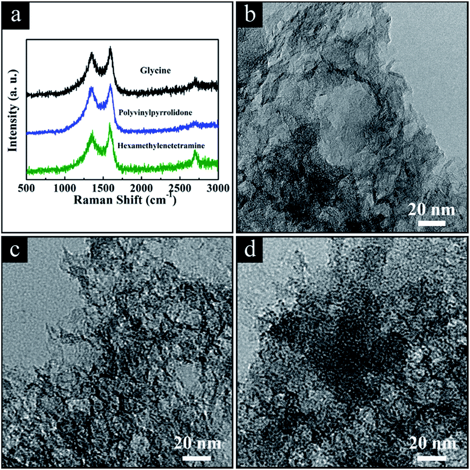 | ||
| Fig. 10 (a) Raman spectra and TEM images of the HPGC samples using (b) glycine, (c) polyvinylpyrrolidone, and (d) hexamethylenetetramine replacing urea, respectively. | ||
4 Conclusions
In summary, we have achieved hierarchical porous graphitic carbons by one-step metallothermic reaction, where Mg performed as the reductant to generate C from CO2 thermally decomposed from urea and zinc acetate dehydrates, and the unique combination of micro-, meso- and macropores were induced by the evaporation of abundant gases and the dual hard template of MgO and ZnO particles. This method can be easily extended to other chemical substances by replacing urea with e.g. glycine, polyvinylpyrrolidone, and hexamethylenetetramine. The hierarchical porous structure and good conductivity can increase the accessible surface area for charge storage, minimize the diffusion distances and resistance of ions, and fasten the ions transport, leading to high specific capacitance, capacity retention, long-term cycling stability as well as high energy density and power density under severe conditions. Together with the simple procedure, low cost and easy post-treatment, this work may have provided a fresh route to produce HPGCs with high supercapacitive performance.Acknowledgements
This work is financially supported by the National Natural Science Foundation of China (21473045, 51401066), the Fundamental Research Funds from the Central University (PIRS OF HIT A201503), and State Key Laboratory of Urban Water Resource and Environment, Harbin Institute of Technology (2015TS06).Notes and references
- C. Liu, F. Li, L. P. Ma and H. M. Cheng, Adv. Mater., 2010, 22, E28–E62 CrossRef CAS PubMed.
- P. Simon and Y. Gogotsi, Nat. Mater., 2008, 7, 845–854 CrossRef CAS PubMed.
- F. Béguin, V. Presser, A. Balducci and E. Frackowiak, Adv. Mater., 2014, 26, 2219–2251 CrossRef PubMed.
- H. Jiang, P. S. Lee and C. Z. Li, Energy Environ. Sci., 2013, 6, 41–53 CAS.
- B. Fang, J. H. Kim, M. S. Kim and J. S. Yu, Acc. Chem. Res., 2013, 46, 1397–1406 CrossRef CAS PubMed.
- Y. F. Zhao, W. Ran, J. He, Y. F. Song, C. M. Zhang, D. B. Xiong, F. M. Gao, J. S. Wu and Y. Y. Xia, ACS Appl. Mater. Interfaces, 2015, 7, 1132–1139 CAS.
- X. Y. Zheng, J. Y. Luo, W. Lv, D. W. Wang and Q. H. Yang, Adv. Mater., 2015, 27, 5388–5395 CrossRef CAS PubMed.
- T. Q. Lin, I. W. Chen, F. X. Liu, C. Y. Yang, H. Bi, F. F. Xu and F. Q. Huang, Science, 2015, 350, 1508–1513 CrossRef CAS PubMed.
- L. Sun, C. G. Tian, Y. Fu, Y. Yang, J. Yin, L. Wang and H. G. Fu, Chem.–Eur. J., 2014, 20, 564–574 CrossRef CAS PubMed.
- D. W. Wang, F. Li, M. Liu, G. Q. Lu and H. M. Cheng, Angew. Chem., Int. Ed., 2008, 47, 373–376 CrossRef CAS PubMed.
- C. Chen, D. F. Yu, G. Y. Zhao, B. S. Du, W. Tang, L. Sun, Y. Sun, F. Besenbacher and M. Yu, Nano Energy, 2016, 15, 377–389 CrossRef.
- Z. K. Kou, B. B. Guo, Y. F. Zhao, S. F. Huang, T. Meng, J. Zhang, W. Q. Li, I. S. Amiinu, Z. H. Pu, M. Wang, M. Jiang, X. B. Liu, Y. F. Tang and S. C. Mu, ACS Appl. Mater. Interfaces, 2017, 9, 3702–3712 CAS.
- Y. F. Zhao, S. F. Huang, M. R. Xia, S. Rehman, S. C. Mu, Z. K. Kou, Z. Zhang, Z. Y. Chen, F. M. Gao and Y. L. Hou, Nano Energy, 2016, 28, 346–355 CrossRef CAS.
- Q. Wang, J. Yan and Z. J. Fan, Energy Environ. Sci., 2016, 9, 729–762 CAS.
- L. Sun, C. G. Tian, L. Wang, J. L. Zou, G. Mu and H. G. Fu, J. Mater. Chem., 2011, 21, 7232–7239 RSC.
- J. H. Hou, C. B. Cao, F. Idrees and X. L. Ma, ACS Nano, 2015, 9, 2556–2564 CrossRef CAS PubMed.
- D. Eisenberg, W. Stroek, N. J. Geels, C. S. Sandu, A. Heller, N. Yan and G. Rothenberg, Chem.–Eur. J., 2016, 22, 501–505 CrossRef CAS PubMed.
- J. Y. Liang, C. C. Wang and S. Y. Lu, J. Mater. Chem. A, 2015, 3, 24453–24462 CAS.
- M. Armand, F. Endres, D. R. Macfarlane, H. Ohno and B. Scrosati, Nat. Mater., 2009, 8, 621–629 CrossRef CAS PubMed.
- A. Brandt, S. Pohlmann, A. Varzi, A. Balducci and S. Passerini, MRS Bull., 2013, 38, 554–559 CrossRef CAS.
- A. Lewandowski, A. Olejniczak, M. Galinski and I. Stepniak, J. Power Sources, 2010, 195, 5814–5819 CrossRef CAS.
- R. Y. Lin, P. L. Taberna, S. Fantini, V. Presser, C. R. Pérez, F. Malbosc, N. L. Rupesinghe, K. B. K. Teo, Y. Gogotsi and P. Simon, J. Phys. Chem. Lett., 2011, 2, 2396–2401 CrossRef CAS.
- K. Tochigi and H. Yamamoto, J. Phys. Chem. C, 2007, 111, 15989–15994 CAS.
- R. S. Hastak, P. Sivaraman, D. D. Potphode, K. Shashidhara and A. B. Samui, Electrochim. Acta, 2012, 59, 296–303 CrossRef CAS.
- S. K. Kim, H. J. Kim, J. C. Lee, P. V. Braun and H. S. Park, ACS Nano, 2015, 9, 8569–8577 CrossRef CAS PubMed.
- X. J. Li, W. Xing, J. Zhou, G. Q. Wang, S. P. Zhuo, Z. F. Yan, Q. Z. Xue and S. Z. Qiao, Chem.–Eur. J., 2014, 20, 13314–13320 CrossRef CAS PubMed.
- X. H. Liu, Z. B. Wen, D. B. Wu, H. L. Wang, J. H. Yang and Q. G. Wang, J. Mater. Chem. A, 2014, 2, 11569–11573 CAS.
- M. B. V. Santos, E. Geissler, K. László, J. N. Rouzaud, A. M. Alonso and J. M. D. Tascón, J. Phys. Chem. C, 2012, 116, 257–268 Search PubMed.
- L. Tang, J. J. Wang, C. T. Jia, G. X. Lv, G. Xu, W. T. Li, L. Wang, J. Y. Zhang and M. H. Wu, Appl. Catal., B, 2017, 205, 587–596 CrossRef CAS.
- G. X. Li, Y. L. Li, H. B. Liu, Y. B. Guo, Y. J. Li and D. B. Zhu, Chem. Commun., 2010, 46, 3256–3258 RSC.
- J. L. Figueiredo and M. F. R. Pereira, Catal. Today, 2010, 150, 2–7 CrossRef CAS.
- B. Z. Fang, A. Bonakdarpour, M. S. Kim, J. H. Kim, D. P. Wilkinson and J. S. Yu, Microporous Mesoporous Mater., 2013, 182, 1–7 CrossRef CAS.
- S. S. Zheng, H. Ju and X. Lu, Adv. Energy Mater., 2015, 5, 1500871–1500879 CrossRef.
- L. Hao, X. L. Li and L. J. Zhi, Adv. Mater., 2013, 25, 3899–3904 CrossRef CAS PubMed.
- P. M. Schaber, J. Colson, S. Higgins, D. Thielen, B. Anspach and J. Brauer, Thermochim. Acta, 2004, 424, 131–142 CrossRef CAS.
- C. C. Lin and Y. Y. Li, Mater. Chem. Phys., 2009, 113, 334–337 CrossRef CAS.
- Z. Y. Xing, B. Wang, W. Y. Gao, C. Q. Pan, J. K. Halsted, E. Chong, J. Lu, X. F. Wang, W. Luo, C. H. Chang, Y. H. Wen, S. Q. Ma, K. Amine and X. L. Ji, Nano Energy, 2015, 11, 600–610 CrossRef CAS.
- L. Yang, S. Cheng, Y. Ding, X. B. Zhu, Z. L. Wang and M. L. Liu, Nano Lett., 2012, 12, 321–325 CrossRef CAS PubMed.
- W. Y. Tsai, R. Y. Lin, S. Murali, L. L. Zhang, J. K. McDonough, R. S. Ruoff, P. L. Taberna, Y. Gogotsi and P. Simon, Nano Energy, 2013, 2, 403–411 CrossRef CAS.
Footnote |
| † Electronic supplementary information (ESI) available. See DOI: 10.1039/c7ra06234f |
| This journal is © The Royal Society of Chemistry 2017 |