 Open Access Article
Lead-free and stable antimony–silver-halide double perovskite (CH3NH3)2AgSbI6†
Ya-Juan Li‡
ab,
Tao Wu‡c,
Lei Suna,
Rui-Xia Yanga,
Lei Jianga,
Peng-Fei Chengab,
Qun-Qing Haoab,
Tian-Jun Wanga,
Rui-Feng Luc and
Wei-Qiao Deng *a
*a
aState Key Laboratory of Molecular Reaction Dynamics, Dalian Institute of Chemical Physics, Chinese Academy of Science, Dalian 116023, P. R. China. E-mail: dengwq@dicp.ac.cn
bUniversity of the Chinese Academy of Sciences, Beijing 100039, P. R. China
cDepartment of Applied Physics, Nanjing University of Science and Technology, Nanjing 210094, P. R. China
First published on 13th July 2017
Abstract
A mixed metal organic–inorganic perovskite (CH3NH3)2AgSbI6 was developed in which pairs of the Pb(II) atoms in traditional CH3NH3PbI3 perovskite are replaced by Sb(III)/Ag(I) aliovalent units. We used density functional theory (DFT) calculations (the GLLB-SC method) with spin–orbit coupling corrections to predict the optical band gap of the most stable MA2AgSbI6 structure (2.00 eV). The results suggest that it is a promising light absorber. We then synthesized the double perovskite MA2AgSbI6 and confirmed its structure using X-ray diffraction (XRD). The optical band gap (1.93 eV) is in good agreement with the DFT calculations. The band positions of the material (vs. vacuum) are provided for future uses such as achieving the precise energy level alignments for potential photovoltaic applications. This perovskite material exhibits excellent stability in ambient air.
1. Introduction
Organic–inorganic hybrid perovskite materials such as CH3NH3PbI3 (MAPbI3) have attracted broad interest in recent years for thin film solar cells. This is because of their high performance and low cost.1–4 The power conversion efficiency (PCE) of solar cells with organic–inorganic metal trihalide perovskites has increased from 3.8% (ref. 5) to 22.1%,6 which is comparable to those of commercial silicon solar cells. However, several drawbacks greatly hamper their use in large-scale applications: (I) the PCE is significantly affected by different measurement delay times, scan direction, light, and voltage bias pre-treatments;7–10 (II) the PCE decreases sharply if the temperature is above 85 °C and humidity above 80%;11 and (III) Pb is a bioaccumulative and toxic element. In regard to the first drawback, interface optimization or modification has been used to decrease the hysteresis of perovskite-based solar cells.12,13 Han and co-workers found that the addition of 5-ammoniumvaleric acid (5-AVA) in a TiO2–ZrO2-MAPbI3-carbon cell improves the stability of the solar cell.14 Additionally, the solar cell stability improves upon compositional engineering such as doping with Cs+ or Rb+ in a mixed-cation lead mixed-halide perovskite absorber,11,15 or substituting spiro-oMeTAD for an inorganic hole transporting material.16–18 Layered two-dimensional perovskites such as (PEA)2(MA)2[Pb3I10] have also been used as absorbers to enhance the moisture stability of the solar cells.19 While the stability of the devices is enhanced, the Pb pollution is still a concern. Therefore, perovskite crystalline structures containing Sn2+ or Ge2+ (same group as Pb), which have a low toxicity, have been used for the light absorption layer. However, both the device performance and stability are not ideal. The PCE of solar cells based on MAGeI3 have only reached 0.2%. The inadequate device performance can be attributed to a poor open circuit voltage resulting from Ge oxidation (Ge2+ → Ge4+).20 Additionally, Sn2+ is also easily prone to be oxidized to the tetravalent state, yielding a maximum efficiency of only 6.4% only under a N2 atmosphere.21–24 These issues, together, have pushed researchers to find new air-stable and non-toxic lead-free halide perovskites for photovoltaic application. Recently, developments of Bi3+ and Sb3+ related double perovskites have been explored using both theoretical and experimental methods.25,26Cs3B2X9 (B = Bi, Sb, X = I, Br, Cl) related to cesium lead halides have been investigated for their luminescence properties in 1970s and 1980s.27–29 The phase transition of MA3B2I9 (B = Sb, Bi) at different temperature were also studied to explore their potential applications as ferroelectric and dielectric materials in later 1990s.30–35 These materials have a hexagonal crystalline phase, which can exhibited either 0-D dimers or 2-D layered structure based on the preparation method.36 Among them, Cs3Bi2I9 has been reported with a PCE of over 1%,37 while MA3Sb2I9 and MA3Bi2I9 can have PCEs of ∼0.5% and ∼0.2%, respectively.38–40 Furthermore, mixed metal double perovskites with a basic formula A2B′B″X6(A = Cs; B′ = Cu, Ag, Au; B″ = Bi, Sb; X = I, Br, Cl) exhibit tunable band gaps and lower carrier effective masses.26 It is for these reasons that they have attracted intention as an alternative to MAPbI3. Cs2AgBiBr6 (2.19 eV) and Cs2AgBiCl6 (2.77 eV) has been examined to consist of two types of octahedral alternating in rock-salt face-centered cubic structure.41,42 Cs2AgBiBr6 is predicted to be a promising photovoltaic material with long carrier recombination lifetime,43,44 however, it has narrow stable chemical potential region.45 Deng et al. screened hybrid double perovskites MA2B′BiX6 (B′ = Cu, Ag; X = Cl, Br, I) with band gaps similar to those of the MAPbX3. However, MA2CuBiX6 was found to be unstable.46 Later, MA2KBiCl6 (3.04 eV)47 and MA2AgBiBr6 (2.02 eV)45 were also synthesized for potential photovoltaic applications. However, MA2B′SbX6 materials have not yet been reported.
To address a stable lead-free perovskite material, we replaced the pairs of Pb(II) atoms with Sb(III)/Ag(I) aliovalent units, thus resulting in an alternative mixed metal organic–inorganic perovskite MA2AgSbI6. In this regard, we first used DFT calculations to predict its properties before synthesizing the material. Its experimental properties are in good agreement with the calculated predictions. MA2AgSbI6 exhibits efficient optical absorption and has a high stability, therefore making it a promising absorber for lead-free perovskites solar cells.
2. Experimental section
2.1 Theoretical calculation
All structure optimization were performed by using the generalized gradient approximation (GGA) with density functional theory (DFT) as implemented in the Vienna ab initio simulation package (VASP).48,49 The projector augmented-wave method is applied to describe the interaction between electron and ion.50 The Perdew–Burke–Ernzerhof (PBE) functional was chosen to describe the electron exchange–correlation.51 In particular, the kinetic energy cutoff for plane wave basis set was set to 500 eV, and the numerical convergence criteria was 10−4 eV for the energy and 0.02 eV Å−1 for the force. A Monkhorst–Pack k point mesh of 6 × 6 × 4 was used for all calculations. The lattice and atom positions of all suspected structures are fully optimized without any symmetry constraints.2.2 The material preparation
The MA2AgSbI6 was prepared by solid state reactions in a sealed vacuum tube.52 502 mg (1 mmol) SbI3, 234 mg (1 mmol) AgI and 318 mg (2 mmol) MAI were ground uniformly in an agate mortar inside an Ar2 gas glove box to ensure a homogenous mixture. This yielded a light red powder, which was sealed in an evacuated (mechanical pump for 40 min) 1 cm × 10 cm quartz ampere tube. The powder turned into a crimson color after loading the tube in an oven with constant temperature 150 °C for 2 h.2.3 Characterization
The solid UV-Vis absorption spectra were recorded using a JASCO V-550 UV-Vis spectrophotometer. The XRD spectra were recorded using an Empyrean X-ray diffractometer with Cu Kα radiation (λ = 1.54 Å). The UPS measurements were carried out using a He I (hν = 21.2 eV) source in a UHV chamber. The morphology of the powder was characterized by FESEM (JSM-7800F) and TEM (JEM-2100).3. Results and discussion
The tolerance factor was calculated to evaluate the metal ionic radii mismatch for the MA2AgSbI6 double perovskite material. Using the approach introduced by V. M. Goldschmidt,53 the tolerance factor equation can be expressed as follows:In our research system, rA and rX are the effective ionic radii of the MA and iodide, which are 180 pm and 220 pm,54 respectively. rB is the effective ionic radius of the metal with six-coordinates. Considering that there are two metal elements in our system (Sb and Ag) with effective ionic radii corresponding to 76 pm and 115 pm,55 we set rB to their average value (95.5 pm). The calculated tolerance factor of MA2AgSbI6 is 0.90, which is a little larger than that observed for MAPbI3 (0.83). This indicates that MA2AgSbI6 can form a basic perovskite structure.
The orientation of MA cation in tetragonal phase affects the structural stability and electronic properties of MAPbI3, which has been fully discussed by Claudio et al.56 Herein, we considered ten different orientations of the MA cation in MA2AgSbI6. The orientation of the MA cation can be described by the angle of the MA cation projection in the ab-plane with respect to the a-axis (θ = 45°, 135°, 225°, 315°) and the angle of the MA cation with respect to the ab plane (φ = 30°, −30°). These orientations are illustrated in Scheme S1 (ESI†). After constructing the MA2AgSbI6 structures with different MA cation orientations (Table S1†), we start the structural optimization of the tetragonal phase. All ten optimized structures (denoted as number 1–10 in Fig. 1), with the exceptions of structure 3(α = 90.5°, β = 89.2°, γ = 84.5°) and 9(α = 90.1°, β = 91.2°, γ = 96.6°) clearly exhibit the orthogonal phase. Structures 3 and 9 each have structural distortions, which tend to form hexagonal structures. This serves as evidence that the orientation of the MA cation influences the inorganic framework. The calculated relative energies and band gaps are listed in Table 1. Structures 9 and 3 have lower relative energies than the other structures (∼0.2–0.4 eV), which explains why both of these structures exhibit large distortions from the orthogonal phase and prefer the hexagonal configuration. Additionally, there are three groups in terms of band gap classification: small gaps (0.00 to 0.10 eV), mid-sized gaps (0.60 to 0.80 eV), and large gaps (1.10 to 1.30 eV). The broad gap range indicates that the band gap of MA2AgSbI6 is heavily affected by the orientation of the MA cation and the inorganic framework. This may be due to different electronic couplings between the MA cation and the metal–iodine framework. Moreover, there are two distinct types of metal–iodine bonds (Sb–I and Ag–I) in MA2AgSbI6. This differs from MAPbI3, which has only one type of metal–iodine bond (Pb–I). The orientation of the MA cation therefore affects MA2AgSbI6 more significantly than MAPbI3.56
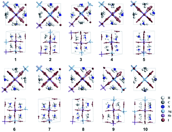 | ||
| Fig. 1 Ten optimized structures (1–10) of MA2AgSbI6. The views along the [001] and [110] planes are shown for each structure. | ||
| Structure | Lattice parameters (a, b, c) | Relative energy | Eg |
|---|---|---|---|
| 1 | 8.51, 8.52, 13.02 | 0.19 | 0.61 |
| 2 | 8.46, 8.50, 13.22 | 0.17 | 0.75 |
| 3 | 8.54, 8.59, 13.35 | 0.04 | 1.16 |
| 4 | 8.49, 8.50, 13.08 | 0.27 | 0.65 |
| 5 | 8.45, 8.51, 13.21 | 0.45 | 0.09 |
| 6 | 8.47, 8.52, 13.19 | 0.27 | 0.66 |
| 7 | 8.45, 8.50, 13.27 | 0.44 | 0.02 |
| 8 | 8.45, 8.47, 13.31 | 0.17 | 0.73 |
| 9 | 8.59, 8.55, 13.37 | 0 | 1.25 |
| 10 | 8.48, 8.46, 13.35 | 0.27 | 0.79 |
Structure 9 is the most stable structure as it has the lowest energy based on calculations using the PBE functional. Additionally, the PBE functional shows that its band gap (1.25 eV) is appropriate for photovoltaic application. In light of this, we focus on structure 9 in the following discussion. Considering standard DFT calculations seriously underestimate semiconductor band gaps, the inclusion of relativistic effects is important to calculate more accurate band gaps for hybrid perovskites. The GLLB-SC model potential method57 implemented in the GPAW code,58 was previously used to predict the band gaps for hybrid organic–inorganic perovskites. The mean absolute error was only 0.2 eV compared with experiments.59 The band gap (2.12 eV) of structure 9 was calculated by using this method. To further improve the accuracy, spin–orbit coupling (SOC) calculations were also taken into account. The SOC effect induces a small decrease in the band gap (∼0.12 eV), which results in a band gap of 2.00 eV for structure 9. This proper band gap means MA2AgSbI6 may exhibit efficient absorption in the visible light region. The band dispersion of structure 9 is depicted in Fig. 2 using the PBE functional. The valence band maximum (VBM) is located at the K point whereas the conduction band minimum (CBM) is at the N point, thus indicating that MA2AgSbI6 has an indirect band gap. Similar to silicon, this means that photoelectric conversion in MA2AgSbI6 requires the aid of lattice phonons. Further, we calculated the effective mass of MA2AgSbI6 to evaluate its charge transport properties. Based on the DFT calculations, we obtain a hole effective mass of  and 4.49 along the K–M and K–Λ directions. However, the electron effective masses are
  and 0.53 along the N–Λ and N–Γ directions, respectively. These results imply that charge transport is anisotropic and electron transport is much faster than hole transport. Its effective mass of the electron are comparable to MAPbI3,60 which indicates that MA2AgSbI6 exhibits facile electron transport properties. Moreover, the charge densities of the VBM and CBM of structure 9 are plotted in Fig. 3. The charge density of VBM is mainly distributed around I and Ag atoms, while the charge density of CBM is localized mostly on the Sb atoms. This is beneficial for charge separation in photovoltaic application.
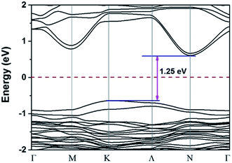 | ||
| Fig. 2 PBE calculated band structure of 9 in the first Brillouin zone; the Fermi level is set to be zero. | ||
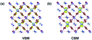 | ||
| Fig. 3 Partial orbital charge density of VBM (a) and CBM (b), respectively. The isosurface level is 0.005 [purple: Sb; silvery: Ag; brown: I; grey: C; blue: N; white: H atoms]. | ||
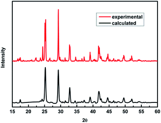
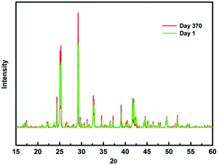
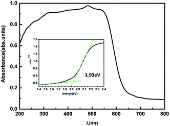
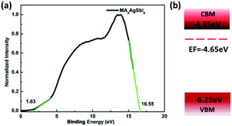
To verify our theoretical predictions, we synthesized the MA2AgSbI6 perovskite by a solid–state reaction (the detailed synthetic method is listed in the Experimental section). Its powder XRD spectrum coincides well with the simulated one (Fig. 4). The XRD spectrum, outside of peak intensity, was the same (Fig. S1†) for each of the three different preparation temperatures 150 °C, 200 °C and 220 °C. This demonstrated the new material is stable in broad temperature range. Notably, the XRD spectrum for the powder is relatively unaltered after being exposed to air for 370 days (Fig. 5). We find the peak intensity increases, which may be attributed to the different crystal sizes. However, there are no additional peaks associated with degradation products. The material is therefore more stable than MAPbI3, which will partially decompose to PbI2 yellow powder as shown by XRD spectrum or the naked eye.43 The thermal decomposition temperature, based on thermogravimetric analysis, can reach up to 260 °C (Fig. S2†) in N2 gas flow. This material therefore exhibits excellent air and thermal stability. The synthesized crimson powder efficiently absorbs light in the ultraviolet-visible range of 200–650 nm (Fig. 6), and has an optical band gap of 1.93 eV (based on the Tauc plot shown in the Fig. 6 inset). The band gap is close to the theoretical prediction. Moreover, the powder exhibits a poly-crystalline morphology as shown in the SEM and TEM images, and further confirmed by the TEM selected area electron diffraction (SAED) pattern (Fig. S3†). The Fermi level (4.65 eV) of MA2AgSbI6 was also obtained from the cut-off energy (16.55 eV) of ultraviolet photoelectron spectrum (Fig. 7) and the energy (21.2 eV) of the He I source. The VBM position is 1.63 eV lower than the Fermi level. The CBM position was calculated according to the optical band gap (1.93 eV), which was obtained from absorption spectrum. The Fermi level is closed to the CBM, which indicates that it may be an N-type semiconductor (Fig. 7). The energy level alignment is provided as a reference for future endeavors to achieve precise band alignments for high performance photovoltaic devices.
4. Conclusions
In summary, we synthesized a new kind of antimony and silver based double perovskite material with a band gap of 1.93 eV. Both DFT calculations and experimental results are in good agreement. The new double perovskite exhibits a high stability in ambient conditions (room temperature, in air at 20–60% humidity) for 370 days. The ideal band gap and excellent stability make this material a promising absorber for photovoltaic applications.Acknowledgements
This work was supported by the Ministry of Science and Technology of China (grant number 2017YFA0204800) and National Natural Science Foundation of China (grant number 21525315, 21403211, and 91333116).References
- M. M. Lee, J. Teuscher, T. Miyasaka, T. N. Murakami and H. J. Snaith, Science, 2012, 338, 643–647 CrossRef CAS PubMed.
- J. Burschka, N. Pellet, S.-J. Moon, R. Humphry-Baker, P. Gao, M. K. Nazeeruddin and M. Graetzel, Nature, 2013, 499, 316 CrossRef CAS PubMed.
- X. Li, D. Bi, C. Yi, J.-D. Decoppet, J. Luo, S. M. Zakeeruddin, A. Hagfeldt and M. Gratzel, Science, 2016, 353, 58–62 CrossRef CAS PubMed.
- W. S. Yang, J. H. Noh, N. J. Jeon, Y. C. Kim, S. Ryu, J. Seo and S. I. Seok, Science, 2015, 348, 1234–1237 CrossRef CAS PubMed.
- A. Kojima, K. Teshima, Y. Shirai and T. Miyasaka, J. Am. Chem. Soc., 2009, 131, 6050 CrossRef CAS PubMed.
- National Renewable Energy Laboratory, Best Research-Cell Efficiencies, http://www.nrel.gov/pv/assets/images/efficiency_chart.jpg, 2016 Search PubMed.
- E. L. Unger, E. T. Hoke, C. D. Bailie, W. H. Nguyen, A. R. Bowring, T. Heumueller, M. G. Christoforo and M. D. McGehee, Energy Environ. Sci., 2014, 7, 3690–3698 CAS.
- W. Tress, N. Marinova, T. Moehl, S. M. Zakeeruddin, M. K. Nazeeruddin and M. Grätzel, Energy Environ. Sci., 2015, 8, 995–1004 CAS.
- Z. G. Xiao, Y. B. Yuan, Y. C. Shao, Q. Wang, Q. F. Dong, C. Bi, P. Sharma, A. Gruverman and J. S. Huang, Nat. Mater., 2015, 14, 193–198 CrossRef CAS PubMed.
- Y. H. Zhang, P. Wang, X. G. Yu, J. S. Xie, X. Sun, H. H. Wang, J. B. Huang, L. B. Xu, C. Cui, M. Lei and D. R. Yang, J. Mater. Chem. A, 2016, 4, 18509–18515 CAS.
- D. P. McMeekin, G. Sadoughi, W. Rehman, G. E. Eperon, M. Saliba, M. T. Hoerantner, A. Haghighirad, N. Sakai, L. Korte, B. Rech, M. B. Johnston, L. M. Herz and H. J. Snaith, Science, 2016, 351, 151–155 CrossRef CAS PubMed.
- H. P. Zhou, Q. Chen, G. Li, S. Luo, T. B. Song, H. S. Duan, Z. R. Hong, J. B. You, Y. S. Liu and Y. Yang, Science, 2014, 345, 542–546 CrossRef CAS PubMed.
- D. Yang, R. Yang, X. Ren, X. Zhu, Z. Yang, C. Li and S. Liu, Adv. Mater., 2016, 28, 5206 CrossRef CAS PubMed.
- A. Mei, X. Li, L. Liu, Z. Ku, T. Liu, Y. Rong, M. Xu, M. Hu, J. Chen, Y. Yang, M. Graetzel and H. Han, Science, 2014, 345, 295–298 CrossRef CAS PubMed.
- M. Saliba, T. Matsui, K. Domanski, J. Y. Seo, A. Ummadisingu, S. M. Zakeeruddin, J. P. Correa-Baena, W. R. Tress, A. Abate, A. Hagfeldt and M. Gratzel, Science, 2016, 354, 206–209 CrossRef CAS PubMed.
- W. Chen, Y. Wu, Y. Yue, J. Liu, W. Zhang, X. Yang, H. Chen, E. Bi, I. Ashraful, M. Graetzel and L. Han, Science, 2015, 350, 944–948 CrossRef CAS PubMed.
- F. Zhang, X. Yang, M. Cheng, W. Wang and L. Sun, Nano Energy, 2016, 20, 108–116 CrossRef CAS.
- R. F. Service, Science, 2016, 351, 113–114 CrossRef CAS PubMed.
- I. C. Smith, E. T. Hoke, D. Solis-Ibarra, M. D. McGehee and H. I. Karunadasa, Angew. Chem., Int. Ed., 2014, 53, 11232–11235 CrossRef CAS PubMed.
- T. Krishnamoorthy, H. Ding, C. Yan, W. L. Leong, T. Baikie, Z. Zhang, M. Sherburne, S. Li, M. Asta, N. Mathews and S. G. Mhaisalkar, J. Mater. Chem. A, 2015, 3, 23829–23832 CAS.
- F. Hao, C. C. Stoumpos, D. H. Cao, R. P. H. Chang and M. G. Kanatzidis, Nat. Photonics, 2014, 8, 489–494 CrossRef CAS.
- N. K. Noel, S. D. Stranks, A. Abate, C. Wehrenfennig, S. Guarnera, A.-A. Haghighirad, A. Sadhanala, G. E. Eperon, S. K. Pathak, M. B. Johnston, A. Petrozza, L. M. Herz and H. J. Snaith, Energy Environ. Sci., 2014, 7, 3061–3068 CAS.
- M. H. Kumar, S. Dharani, W. L. Leong, P. P. Boix, R. R. Prabhakar, T. Baikie, C. Shi, H. Ding, R. Ramesh, M. Asta, M. Graetzel, S. G. Mhaisalkar and N. Mathews, Adv. Mater., 2014, 26, 7122 CrossRef CAS PubMed.
- T. B. Song, T. Yokoyama, C. C. Stoumpos, J. Logsdon, D. H. Cao, M. R. Wasielewski, S. Aramaki and M. G. Kanatzidis, J. Am. Chem. Soc., 2017, 139, 836–842 CrossRef CAS PubMed.
- Z. Shi, J. Guo, Y. Chen, Q. Li, Y. Pan, H. Zhang, Y. Xia and W. Huang, Adv. Mater., 2017, 29, 1605005 CrossRef PubMed.
- G. Volonakis, M. R. Filip, A. A. Haghighirad, N. Sakai, B. Wenger, H. J. Snaith and F. Giustino, J. Phys. Chem. Lett., 2016, 7, 1254–1259 CrossRef CAS PubMed.
- B. Chabot and E. Parthe, Acta Crystallogr., Sect. B: Struct. Crystallogr. Cryst. Chem., 1978, 34, 645–648 CrossRef.
- C. W. M. Timmermans and G. Blasse, Phys. Status Solidi B, 1981, 106, 647–655 CrossRef CAS.
- C. W. M. Timmermans, S. O. Cholakh and G. Blasse, J. Solid State Chem., 1983, 46, 222–233 CrossRef CAS.
- R. Jakubas and L. Sobczyk, Phase Transitions, 1990, 20, 163–193 CrossRef CAS.
- J. Zaleski, R. Jakubas and L. Sobczyk, Ferroelectrics, 1990, 103, 83–90 CrossRef CAS.
- R. Jakubas, R. Decressain and J. Lefebvre, J. Phys. Chem. Solids, 1992, 53, 755–759 CrossRef CAS.
- P. Koziol, Y. Furukawa, D. Nakamura and R. Jakubas, Bull. Chem. Soc. Jpn., 1992, 65, 1707–1709 CrossRef CAS.
- G. Bator, R. Jakubas, J. Baran and H. Ratajczak, Vib. Spectrosc., 1995, 8, 425–433 CrossRef CAS.
- C. Pawlaczyk, R. Jakubas and H. G. Unruh, Solid State Commun., 1998, 108, 247–250 CrossRef CAS.
- K. Yamada, H. Sera, S. Sawada, H. Tada, T. Okuda and H. Tanaka, J. Solid State Chem., 1997, 134, 319–325 CrossRef CAS.
- B. Saparov, F. Hong, J. P. Sun, H. S. Duan, W. W. Meng, S. Cameron, I. G. Hill, Y. F. Yan and D. B. Mitzi, Chem. Mater., 2015, 27, 5622–5632 CrossRef CAS.
- T. Singh, A. Kulkarni, M. Ikegami and T. Miyasaka, ACS Appl. Mater. Interfaces, 2016, 8, 14542–14547 CAS.
- J.-C. Hebig, I. Kühn, J. Flohre and T. Kirchartz, ACS Energy Lett., 2016, 1, 309–314 CrossRef CAS.
- S. Oz, J. C. Hebig, E. W. Jung, T. Singh, A. Lepcha, S. Olthof, J. Flohre, Y. J. Gao, R. German, P. H. M. van Loosdrecht, K. Meerholz, T. Kirchartz and S. Mathur, Sol. Energy Mater. Sol. Cells, 2016, 158, 195–201 CrossRef.
- E. T. McClure, M. R. Ball, W. Windl and P. M. Woodward, Chem. Mater., 2016, 28, 1348–1354 CrossRef CAS.
- M. R. Filip, S. Hillman, A. A. Haghighirad, H. J. Snaith and F. Giustino, J. Phys. Chem. Lett., 2016, 7, 2579–2585 CrossRef CAS PubMed.
- A. H. Slavney, T. Hu, A. M. Lindenberg and H. I. Karunadasa, J. Am. Chem. Soc., 2016, 138, 2138–2141 CrossRef CAS PubMed.
- Z. Xiao, W. Meng, J. Wang and Y. Yan, ChemSusChem, 2016, 9, 2628–2633 CrossRef CAS PubMed.
- F. Wei, Z. Deng, S. Sun, F. Zhang, D. M. Evans, G. Kieslich, S. Tominaka, M. A. Carpenter, J. Zhang, P. D. Bristowe and A. K. Cheetham, Chem. Mater., 2017, 29, 1089–1094 CrossRef CAS.
- Z. Deng, F. Wei, S. Sun, G. Kieslich, A. K. Cheetham and P. D. Bristowe, J. Mater. Chem. A, 2016, 4, 12025–12029 CAS.
- F. Wei, Z. Deng, S. Sun, F. Xie, G. Kieslich, D. M. Evans, M. A. Carpenter, P. D. Bristowe and A. K. Cheetham, Mater. Horiz., 2016, 3, 328–332 RSC.
- G. Kresse and J. Furthmuller, Phys. Rev. B: Condens. Matter Mater. Phys., 1996, 54, 11169–11186 CrossRef CAS.
- G. Kresse and J. Furthmuller, Comput. Mater. Sci., 1996, 6, 15–50 CrossRef CAS.
- P. E. Blochl, Phys. Rev. B: Condens. Matter Mater. Phys., 1994, 50, 17953–17979 CrossRef.
- J. P. Perdew, K. Burke and M. Ernzerhof, Phys. Rev. Lett., 1996, 77, 3865–3868 CrossRef CAS PubMed.
- C. C. Stoumpos, C. D. Malliakas and M. G. Kanatzidis, Inorg. Chem., 2013, 52, 9019–9038 CrossRef CAS PubMed.
- V. M. Goldschmidt, Naturwissenschaften, 1926, 14, 477–485 CrossRef CAS.
- N. K. McKinnon, D. C. Reeves and M. H. Akabas, J. Gen. Physiol., 2011, 138, 453–466 CrossRef CAS PubMed.
- R. D. Shannon, Acta Crystallogr., Sect. A: Cryst. Phys., Diffr., Theor. Gen. Crystallogr., 1976, 32, 751–767 CrossRef.
- C. Quarti, E. Mosconi and F. De Angelis, Chem. Mater., 2014, 26, 6557–6569 CrossRef CAS.
- M. Kuisma, J. Ojanen, J. Enkovaara and T. T. Rantala, Phys. Rev. B: Condens. Matter Mater. Phys., 2010, 82, 3893–3898 CrossRef.
- J. J. Mortensen, L. B. Hansen and K. W. Jacobsen, Phys. Rev. B: Condens. Matter Mater. Phys., 2005, 71, 035109–035119 CrossRef.
- I. E. Castelli, J. M. Garcia-Lastra, K. S. Thygesen and K. W. Jacobsen, APL Mater., 2014, 2, 081514–081520 CrossRef.
- P. Umari, E. Mosconi and F. De Angelis, Sci. Rep., 2014, 4, 4467–4473 CrossRef PubMed.
Footnotes |
| † Electronic supplementary information (ESI) available: See DOI: 10.1039/c7ra06130g |
| ‡ These authors contributed equally to this work. |
| This journal is © The Royal Society of Chemistry 2017 |


