 Open Access Article
Biomimetic structure of carbon fiber cloth grafted with poly(N-isopropylacrylamide) for water collection and smart gates†
Hung-Tao Choua,
Ying-Chieh Chena,
Chi-Young Leea,
Hwan-You Chang*b and
Nyan-Hwa Tai *a
*a
aDepartment of Materials Science and Engineering, National Tsing Hua University, Taiwan. E-mail: nhtai@mx.nthu.edu.tw; Tel: +886 3 5742568
bInstitute of Molecular Medicine, National Tsing Hua University, Hsinchu, 300 Taiwan. E-mail: hychang@mx.nthu.edu.tw; Tel: +886 3 5742910
First published on 26th September 2017
Abstract
An eco-friendly, facile, and efficient method was developed to modify carbon fiber cloth (CFC) having superhydrophobic or hydrophilic properties. The method used polydopamine (PD) as a mediating layer, followed by grafting titanium oxide and poly(N-isopropylacrylamide) (PNIPAM) through mussel adhesion protein-inspired surface chemistry. Carbon fiber cloth with periodic superhydrophobic–hydrophilic patterns was fabricated and its ability for water collection from moisture generated by a humidifier was determined. The patterned CFC exhibited excellent performance in water collection with an efficiency of 206 mg cm−2 h−1, far higher than those of uniform hydrophilic and superhydrophobic surfaces. The carbon fiber cloth grafted with PNIPAM also possesses thermo-responsive properties and swelled dramatically during its volume-phase transition. This study demonstrated that the water permeability of PNIPAM-grafted CFC could be controlled remotely by near infrared laser irradiation. Together, we believe that the modified CFC shows high potential to be used for smart clothes and collecting water from air, and serves as a smart valve in controlling fluid flow for applications in bioreactors and microfluidic systems.
1. Introduction
Marine mussels possess strong adherence abilities on surfaces, which is used in a variety of materials including Teflon, an adhesion-resistant material. Studies of bioadhesive proteins produced by mussels have shown that the dihydroxyphenylalanine–lysine motif is responsible for the high adhesion of the proteins to low-surface-energy materials.1–4 Inspired by this finding, scientists have demonstrated that polydopamine (PD), formed via in situ oxidative self-polymerization of dopamine with an assembled chemical structure similar to adhesive proteins of mussels, also exhibits strong adherence to many surfaces. The presence of carboxyl-, amino-, imino-, and phenyl-groups of the PD coating thin layer turns the surface hydrophilic regardless of its original property. Further functionalization of the PD coating leads to the development of versatile surface modification by using PD as the mediating layer, such as metal nanoparticles or polymer brushes, onto surfaces which are difficult to modify.5–7 In this regard, PD with abundant catechol groups has been demonstrated as a useful surface modifier for most of materials because of the strong adhesion of the catechol groups to a wide range of substances as well as its affinitive interaction with calcium and titanium ions. Along this thought, coating of superhydrophobic titanium oxide (TiO2) and calcium phosphate nanoparticles on material surfaces achieves nano-scale roughness and superhydrophobic property for the material, mimicking the lotus leaves effect.5Recently, processings for the stimuli-responsive surface through surface-initiated atomic transfer radical polymerization (SI-ATRP), Schiff base reaction, or Michael's addition reaction have been proposed. According to the routes, the stimuli-responsive surface with a “PD-g-polymer brush” structure, a PD inner layer and a grafted stimuli-sensitive polymer brush corona, could be obtained, gaining considerable attention from industry and academic because of versatile applications such as control release of fertilizers.6,7
Poly(N-isopropylacrylamide) (PNIPAM) is a well-characterized temperature-responsive polymers. The polymer can transform its structural conformation from expanded random coil to tightly packed globule at the phase separation temperature, leading to the switching of hydrophilic and hydrophobic properties of PNIPAM-based surfaces.8,9 Because of its swelling behavior and volume-phase transition property, PNIPAM has been applied to several fields including drug release and water collection from fog.10,11 Traditional strategies for grafting PNIPAM on substrates include free radical-, light-, or plasma-induced polymerization, providing the substrates with thermo-responsive property.12 Recently, the structure of “PD-g-PNIPAM” has been developed using PD as the primer, which has received wide attention due to its feasibility and environment-friendliness.13
The goal of this study is to develop a flexible material exhibiting controllable surface wettability. This study employs carbon fiber cloth (CFC), having the properties of high conductivity, heat dissipation, mechanical strength, and photothermal effect, as a substrate. Mussel-inspired approaches are used to modify CFCs using PD as a mediating layer, producing a series materials including TiO2-decorated CFC with superhydrophobic property (denoted as TiO2@CFC hereafter), TiO2@CFC with a PD deposition layer (denoted as PD/TiO2@CFC), and PNIPAM-grafted PD/TiO2@CFC (denoted as PNIPAM-PD/TiO2@CFC). Beside TiO2@CFC and PD/TiO2@CFC, two more samples including coating of periodic hydrophilic PD stripes onto TiO2@CFC (denoted as ps-PD/TiO2@CFC) and PNIPAM-grafted ps-PD/TiO2@CFC (denoted as PNIPAM-ps-PD/TiO2@CFC) were fabricated. In this study water harvesting from fog, water evaporation adjustment, and near infrared (NIR)-mediated water permeability control are used as examples to demonstrate versatile applications of PNIPAM-grafted CFCs.
2. Experimental
2.1 Reagents and materials
CFC (PAN, 6–11 μm) and polydimethylsiloxane (PDMS) were obtained from Taiwan Carbon Technology Co., Ltd. and Silmore (Taipei, Taiwan), respectively. Tris (hydroxymethyl) aminomethane was purchased from Acros Organics (New Jersey, USA). PNIPAM–NH2 (molecular weight: 6400; polydispersity index: 1.51), titanium(IV) isopropoxide precursor solution (TTIP, 97% in isopropyl alcohol), dopamine hydrochloride, and Nafion perfluorinated resin solution were purchased from Sigma-Aldrich (St. Louis, Missouri, USA).2.2 Preparation of superhydrophobic TiO2@CFC
Commercial CFC was immersed in acetone and refluxed at 40 °C for 2 days to remove the sizing and was then washed in acetone, ethanol, and water sequentially before oven drying. The treated CFC was immersed in a mixture of dopamine solution (2.0 mg mL−1 in 10 mM Tris buffer pH 8.5) and ethanol (1![[thin space (1/6-em)]](https://www.rsc.org/images/entities/char_2009.gif) :
:![[thin space (1/6-em)]](https://www.rsc.org/images/entities/char_2009.gif) 4, v/v) for 12 h at room temperature.14 Afterward, CFC was washed several times with ethanol and dried in an oven to produce PD-coated CFC.
4, v/v) for 12 h at room temperature.14 Afterward, CFC was washed several times with ethanol and dried in an oven to produce PD-coated CFC.
To decorate TiO2 nanoparticles on CFC, the dried PD-coated CFC was immersed in diluted TTIP (1%, IPA) for 30 s and immediately washed in ethanol after removing the CFC from the solution in order to prevent aggregation of TiO2 on CFC. Finally, CFC was immersed in diluted Nafion (1 v%, ethanol) and then oven dried for obtaining superhydrophobic property.15
2.3 Preparation of PNIPAM-PD/TiO2@CFC and PNIPAM-ps-PD/TiO2@CFC
Oxygen plasma treatment at 50 W was performed for one minute to modify TiO2@CFC surface into temporary hydrophilicity for subsequent PD coating. In addition, TiO2@CFC with a temporary hydrophilic striped pattern were also prepared using a photomask with periodic vertical stripes (as shown schematically in Fig. 1a). Subsequently, the oxygen-plasma-treated CFCs, with the oxygen-plasma-treated side facing down, floated on dopamine solution (1.0 mg mL−1 in Tris–buffer solution, 10 mM, pH 8.5) because of the superhydrophobic property. The surface-modified CFCs were then rinsed three times in ethanol for 30 min and oven dried, completing the fabrication of PD/TiO2@CFC and ps-PD/TiO2@CFC.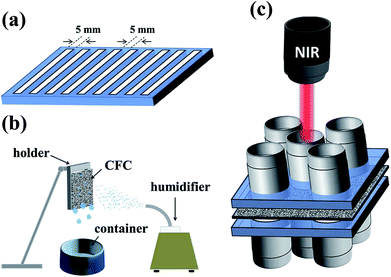 | ||
| Fig. 1 Experimental apparatus utilized in the study. (a) Photomask with periodic vertical stripes. (b) Schematic illustration of the homemade fog-harvesting system. (c) Test of NIR-controlled valve. | ||
To graft PNIPAM on the PD layer, PD/TiO2@CFC and ps-PD/TiO2@CFC, the samples were placed in a container filled with PNIPAM–NH2 (0.5 mg mL−1 in the Tris–buffer solution, 10 mM, pH 8.5), with the PD-coated-side facing down, and subsequently heated to 60 °C for 3 h.16 After cooling to room temperature, both the PD/TiO2@CFC and the ps-PD/TiO2@CFC can also float on the solution, no matter which treated periods, 12 h or 48 h, were used.
Finally, the surface-modified CFCs were rinsed three times in double-distilled water for 30 min and vacuum dried before characterization, thus completing the fabrication of PNIPAM-PD/TiO2@CFC and PNIPAM-ps-PD/TiO2@CFC.
2.4 Characterization of the surface-modified CFCs
The microstructure of CFCs in each stage was examined by field-emission scanning electron microscopy (FE-SEM, JSM-6500, JEOL, Japan and Hitachi SU8010, Japan). Energy dispersive X-ray analysis (EDX, model 7418, UK) was also carried out to study uniformity of the TiO2 nanoparticles decorated on CFC.The contact angle and sliding angle of water droplets on CFC were measured using a commercial contact angle system (OCA 20, Data Physics, Filderstadt, Germany) at ambient temperature using a 10 μL droplet as the indicator. Snapshots were captured using a Canon EOS 7D camera. X-ray photoelectron spectroscopy (XPS, ESCALAB250, VG Scientific, UK) with monochromatic Al Kα X-ray source (1486.6 eV) provided direct evidence of the surface elemental composition and distribution to verify the formation of the surface layer. Fourier-transform infrared spectroscopy (FTIR, Spectrum RX, Perkin-Elmer) was used to examine the functional groups on the PD/TiO2@CFC and PNIPAM-PD/TiO2@CFC.
2.5 Fog harvesting efficiency using the surface-modified CFCs
A homemade test system, as depicted schematically in Fig. 1b, was built to evaluate the fog-harvesting performance of four samples: TiO2@CFC, PD/TiO2@CFC, ps-PD/TiO2@CFC, and PNIPAM-ps-PD/TiO2@CFC. The as-prepared samples (3 cm × 3 cm in size) were fixed on a hanged holder at ambient conditions, and an artificial fog flow (approximately 12 cm s−1) generated by a commercial humidifier was captured by the sample oriented vertically to the fog jet. The distance of 6 cm between the outlet of the humidifier and the CFC sample was maintained. Fog harvesting test was conducted for 3 h under the temperature of 22 °C and a relative humidity between 90–95%, respectively. Water droplets collected on the surfaces ran off by gravity into a container placed beneath the sample.172.6 Water evaporation control using the surface-modified CFCs
To investigate water evaporation rate in different surroundings, a vial filled with distilled water and covered with a lid made of TiO2@CFC, PD/TiO2@CFC, or PNIPAM-PD/TiO2@CFC was designed. The contact edges between CFCs and the vial were sealed with waterproof adhesive glue and PDMS in series to prevent leakage. In addition, a vial without a lid was used as the control. Samples placed under three temperature and relative humidity conditions: 50 °C, 10%; 22 °C, 20%; 24 °C, 70%, were weighed every day to evaluate the water loss.2.7 Water permeation of the surface-modified CFCs controlled by NIR
A piece of PNIPAM-PD/TiO2@CFC was sandwiched by two PDMS substrates (2.5 cm × 2.5 cm, with a central hole of 0.6 cm in diameter) and clamped tightly. To study the influence of NIR laser on the nearby region of the hole, a similar construct with four holes around the center hole, as illustrated schematically in Fig. 1c, was designed. The assembled construct was placed beneath a 808 nm laser beam source with a distance of 5 cm. The NIR laser beam with a power density of 200 mW cm−2 was used to irradiate CFC located at the center hole. The water in the container was maintained at approximately 25 °C, which is below the critical solution temperature (LCST) of PNIPAM (∼32 °C). Finally, an NIR camera placed beneath the gate was used to measure and record the temperature transition of the CFCs after the sample was irradiated.3. Results and discussion
3.1 Characterization of the surface-modified CFCs
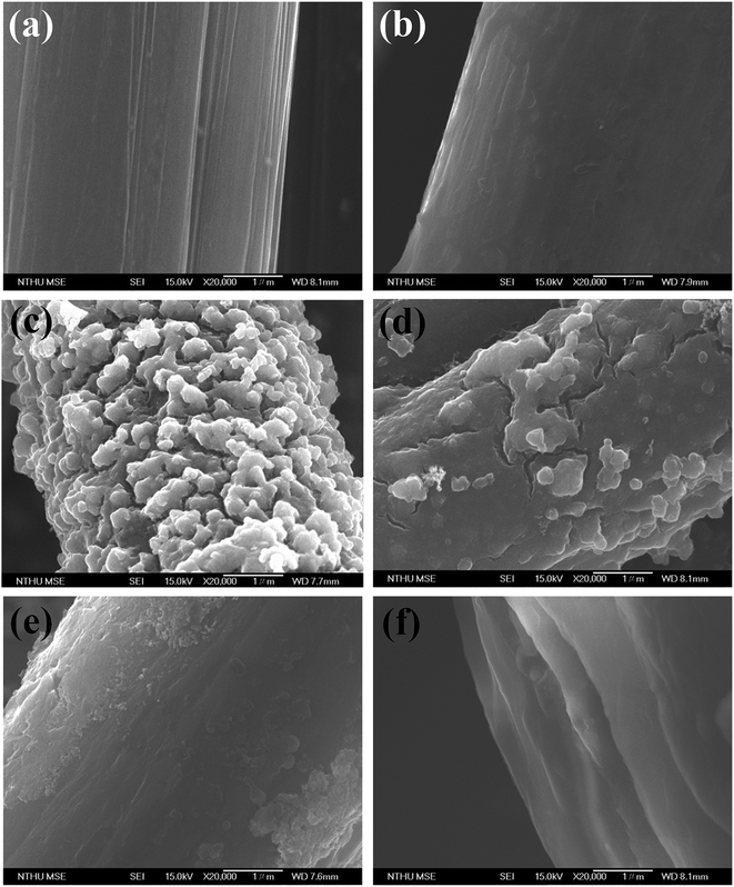
Field-emission scanning electron microscopy (FE-SEM) was used to examine the microstructure of the CFCs subjected to different surface treatments. The fiber surface of the CFC after the acetone washing is relatively smooth (Fig. 2a) showing parallel stripes. Nevertheless, the stripes cannot be found after PD coating (Fig. 2b). Surface morphology of TiO2@CFC (Fig. 2c) displays hierarchical structures containing TiO2 particles having micro- and nano-sizes. Random hierarchical structures are similar to the structure of lotus leaves which had been demonstrated to enhance the superhydrophobicity and its stability.15 Further analysis of TiO2 particles using EDX revealed that approximately 24 wt% of TiO2 particles were uniformly decorated on the CFC (Fig. S1†).In contrast to TiO2@CFC, the surface of PD/TiO2@CFC was relatively smooth (Fig. 2d), indicating homogenous grafting and coverage of the surface by PD. The hierarchical structures and irregular shapes found in TiO2@CFC were still presented in PD/TiO2@CFC suggesting that the PD coating on TiO2@CFC was thin. Comparing with the surface morphology of the PD/TiO2@CFC grafted for 12 h (Fig. 2e), the surface of the PNIPAM-PD/TiO2@CFC grafted for 48 h (Fig. 2f) was relatively smooth at microscopic level, indicating homogenous grafting and coverage of the surface after grafting PNIPAM. In addition, the PNIPAM grafting contributed to increment of diameter (lower magnification FE-SEM is shown in Fig. S2†). Thus, the PNIPAM-PD/TiO2@CFC grafted for 48 h was used in all subsequent studies, FTIR analysis was performed to examine the surface modified with PD and the results are shown in Fig. 3. To simplify the analysis, TiO2@CFC was used as the background to contrast the signal more prominently. Curve (i) representing the characteristics of PD/TiO2@CFC shows peaks at 1515 cm−1 and 1605 cm−1, corresponding to indole and indoline structure, respectively, and a broad signal from 3000 to 3500 cm−1, demonstrating the presence of N–H and O–H bonds, as reported previously.13
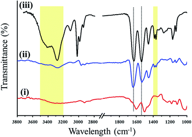 | ||
| Fig. 3 FTIR spectra of PD/TiO2@CFC (curve i), PNIPAM-PD/TiO2@CFC (curve ii), and the comparison group (solely PNIPAM–NH2, curve iii). | ||
Curve (ii) in Fig. 3 depicts the FTIR spectrum of PNIPAM-PD/TiO2@CFC showing characteristic peaks at 1651 and 1551 cm−1, ascribed to the amide I band (stretching vibration of C![[double bond, length as m-dash]](https://www.rsc.org/images/entities/char_e001.gif) O) and amide II band (stretching vibration of N–H), respectively. A broad peak from 3500 to 3200 cm−1 is found owing to the N–H stretching vibration of the secondary amide group. In addition, the characteristic deformation vibration peaks of the C–H bond in the isopropyl group of NIPAM also appear at 1369 and 1388 cm−1. All the position and the number of the bands presented in the PNIPAM-PD/TiO2@CFC (FTIR spectrum (ii)) coincide with the control sample which was prepared by dropping PNIPAM–NH2 solution on the Si wafer (FTIR spectrum (iii)), demonstrating that PNIPAM–NH2 is successfully grafted on the CFC through mussel-inspired surface chemistry.16 The differences in magnitude of the bands between these two curves are attributed to the choice of background which affects the transparency of the sample.
O) and amide II band (stretching vibration of N–H), respectively. A broad peak from 3500 to 3200 cm−1 is found owing to the N–H stretching vibration of the secondary amide group. In addition, the characteristic deformation vibration peaks of the C–H bond in the isopropyl group of NIPAM also appear at 1369 and 1388 cm−1. All the position and the number of the bands presented in the PNIPAM-PD/TiO2@CFC (FTIR spectrum (ii)) coincide with the control sample which was prepared by dropping PNIPAM–NH2 solution on the Si wafer (FTIR spectrum (iii)), demonstrating that PNIPAM–NH2 is successfully grafted on the CFC through mussel-inspired surface chemistry.16 The differences in magnitude of the bands between these two curves are attributed to the choice of background which affects the transparency of the sample.
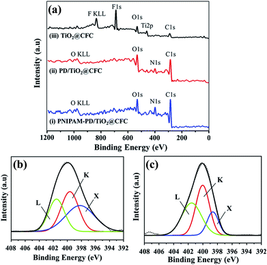
XPS was employed to provide information of the chemical structure of the modified CFCs.12,16,18 Fig. 4 displays a series of wide-scan spectra for surface analyses of different surface-modified CFCs. Depth analyses by using XPS are not suitable because the thickness of the PNIPAM layer immobilized on the PD layer is nearly 4 μm, However, SEM images as shown in Fig. S3a and S3b† demonstrated the thickness of 4 μm.
As expected, the elements of carbon and oxygen existed in all the samples, and the surfaces of PNIPAM-PD/TiO2@CFC (curve i) and PD/TiO2@CFC (curve ii) contain a considerable amount of nitrogen owing to successful grafting of PD and PNIPAM. It is worth mentioning that the disappearance of the Ti and F signals on the PNIPAM-PD/TiO2@CFC and PD/TiO2@CFC may be attributed to the homogenous coating of PD and PNIPAM.
The strongest signal C 1s is not discussed in this study because of the high amount of complex carbon bonds and serious disturbance attributed to the CO2 adsorption by amines.16 Attributing to chemical bonding shifts, variation of N 1s peaks from PD/TiO2@CFC and PNIPAM-PD/TiO2@CFC, can be found from high-resolution element spectra, as shown in Fig. 4b and c, respectively. The deconvoluted N 1s spectra of PD/TiO2@CFC, as depicted in Fig. 4b, clearly shows three component peaks, X (398.2 eV), K (399.64 eV), and L (401.53 eV), resulting from the pyridine–N, C–N bonds of the cyclic amino groups (pyrrolic–N, C–NH–C), and nitrogen atoms of protonated amino groups (C–N+H2–C). These three peaks, especially peak K, could be considered an evidence of adherence of PD on CFC.12,18
The shape of the high-resolution N 1s spectrum did not significantly change after PNIPAM grafting on the PD layer. As shown in Fig. 4c, component peak K appears at 400 eV, which is formed by cyclic amino and carbonic amide groups. In addition, component peaks X and L, two characteristic peaks of PD, still appear even though their ratios to N 1s decrease owing to the covering of PNIPAM onto PD layer. Additional amide groups are provided after grafting PNIPAM on the PD layer, leading to the increment of the relative nitrogen content, for example, the increase in the N/O ratio from 0.283 to 0.625, as determined from the wide-scan spectrum.16,18
3.2 Fog harvesting efficiency of different surface-modified CFCs
Collection of atmospheric moisture is a feasible approach to provide water to semi-arid desert regions as well as water-scarce regions. Stenocara beetle, found in Namib desert, is capable of utilizing its unique shell morphology that consists of hydrophilic wax-free bumpy region and hydrophobic waxy background to collect water from fog for survival.1–3 Inspired by the capability of fog harvesting from Stenocara, this study has developed a CFC with periodic superhydrophobic–hydrophilic patterns and tested its atmospheric moisture capturing efficiency as presented schematically in Fig. 1b.Briefly, a simulated fog flow was generated by a commercial humidifier, and the moisture was captured and collected by the as-prepared condensing CFCs, and finally drained into a container.
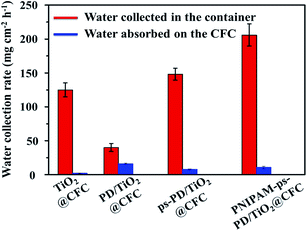
The water collection rates shown by the red columns in Fig. 5 demonstrate that the hydrophilic surface of PD/TiO2@CFC has a water collection efficiency of about 40 mg cm−2 h−1, which is the lowest among the four tested samples. The water collection efficiency increased to 125 mg cm−2 h−1 with the uniform superhydrophobic TiO2@CFC surface. The water harvest rates were even higher and could reach 148 and 206 mg cm−2 h−1, respectively when ps-PD/TiO2@CFC and PNIPAM-ps-PD/TiO2@CFC were used in the assay. No obvious weight differences among the CFC samples were found after harvesting tests, as shown by blue columns in Fig. 5. In addition, it also shows that rarely water can be absorbed in the CFC samples no matter which coating materials was adopted.
An earlier study19 using a uniform hydrophilic surface for fog harvesting demonstrated that the water droplets condensed from the fog, and then tend to spread out, forming a thin film. The high adherent force prevents detaching of the condensed water from the surface. In contrast, the self-cleaning effect of the superhydrophobic surface allows continuous nucleation, growth and removal of droplets, and thus enhancing fog harvesting. On the CFC with periodic superhydrophobic–hydrophilic patterns, tiny water droplets were captured by the superhydrophobic surface preferentially move toward the hydrophilic surface driven by the difference in wettability of the surfaces, thereby accelerating the self-cleaning process of the droplets from the superhydrophobic surfaces. Consequently, higher efficiency of water collection was achieved for the CFC with periodic superhydrophobic–hydrophilic patterns as compared with the substrates having uniform superhydrophobic layer.17,19
CFC with different patterns, including sole horizontal strip and sole vertical strip, as well as the width ratio between the superhydrophobic and hydrophilic strips were prepared for investigating the influence of strip pattern on fog harvesting. However, no obvious difference in water collection rate among those groups can be found, as shown in Fig. S4,† which are opposite to the results published by others.1,20 The published articles suggested that for the fog harvesting, the ideal size of the hydrophilic patterns and the distance between each pattern are 500 μm and 1 mm, respectively, closing to the real morphology of the Stenocara beetle. In addition, star-shape was highly recommended for higher water collection efficiency.
Our work used CFC as the substrate which composed of warp and weft (as shown in Fig. S5†) possessing the width of 100 mm each. Besides, micro-sized pores between fibers having capillarity which results in spread of PNIPAM and dopamine along the space between fibers. Attributing to the fact, it is difficult for us to prepare tiny patterns on the CFC through the coating route used in this work. Therefore, no obvious difference in water collection among these groups could be found.
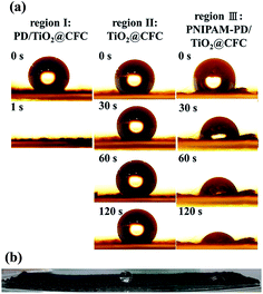
In this work, fog condensed in the superhydrophobic region and migrated to the hydrophilic striped region, subsequently the droplets run off from the CFC cloth once their size is over the detachment threshold. PNIPAM was grafted to ps-PD/TiO2@CFC, denoting as PNIPAM-ps-PD/TiO2@CFC, to effectively remove the coalescent droplets. The material exhibited the highest efficiency of about 1.64 times higher than that of the TiO2@CFC and 1.39 times higher than that of the ps-PD/TiO2@CFC. Fig. 6a shows three snapshots of dynamic contact angle measurement, recording 10 mL water droplets in different regions where subjected to different surface modifications, designated as region I (PD/TiO2@CFC), II (TiO2@CFC), and III (PNIPAM-PD/TiO2@CFC).
Droplet in region I was absorbed by the CFC almost instantly (Fig. 6a), with a water contact angle of less than 2°, indicating a dramatic transformation from a superhydrophobic to a superhydrophilic surface. It is nonbeneficial for a fog harvesting system because an ideal harvesting system needs coexisting of droplet coalescence region and droplet removal regions. Region II shows superhydrophobicity with a static water contact angle of 155° and a sliding angle of 6° ±1° on region I, indicating extremely superhydrophobic surfaces. Compared with region II, the behavior of droplet in region III was slightly different. Once the water droplet contacted the surface in region III, which was grafted with slightly hydrophobic PNIPAM, most of the droplets stayed on the surface, showing an initial contact angle of 110°. The contact angle decreased to approximately 30° after 2 min with no further change thereafter. The phenomenon in region III is attributed to PNIPAM coating that absorbed large amounts of water below LCST, leading to the swelling of the PNIPAM, thus preventing the water droplet from penetrating into the CFC. Fig. 6b shows the wettability of each region after dropping the water on the region for 2 min. It demonstrates that the PNIPAM-grafted surface is a better choice to collocate with TiO2@CFC than the PD-modified surface, providing a CFC with periodic superhydrophobic–hydrophilic patterns for better fog harvesting efficiency.
In short summary, the results indicate that CFC with periodic superhydrophobic–hydrophilic patterns has better performance of fog harvesting than the surface with single wettability. The performance could also be strongly enhance by graft with PNIPAM on hydrophilic patterns. To the best of our knowledge, few of study considered the fog harvesting using the flexible substrate to collect water.
The fog harvesting system used the flexible CFC substrate for collecting water, has high promising potential to be used in different surroundings.
3.3 Water evaporation adjustment using surface-modified CFCs
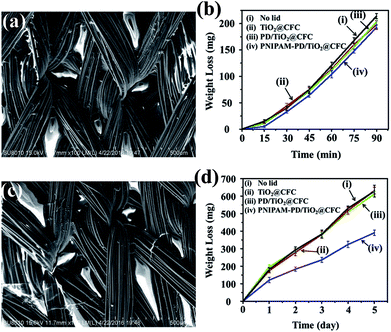
Smart cloth performing cool in summer and warm in winter is highly correlated to the water evaporation because of the higher specific heat and heat conductivity of water than air. An ideal smart cloth is expected to have a high water evaporation rate at high temperatures because of carrying off a large amount of heat. As shown in Fig. 7a, PNIPAM shrink at a temperature above the LCST owing to the predominance of hydrophobic isopropyl-methyl groups, which formed pores within the fiber network of PNIPAM-PD/TiO2@CFC. Fig. 7b depicts water weight loss in vials covered with different CFCs, showing in-significant difference in weight loss for all the vials. According to the results, it is obvious that the PNIPAM-PD/TiO2@CFCs shows a high water evaporation rate, comparable to that of the lid-free vial, at a temperature above the LCST.Fig. 7c shows the FE-SEM images of the PNIPAM-PD/TiO2@CFCs prepared at a temperature below LCST using a freeze-dryer. None-shrinkage of the PNIPAM is formed. As water vapor is absorbed by the surface in trace amounts at a temperature below the LCST, a hydrating layer is formed owing to the dramatic swelling ratio of PNIPAM, thereby decreasing the water evaporation rate. As shown in Fig. 7d. PNIPAM-PD/TiO2@CFC shows only one-third weight loss attributing to low water evaporation rate, as compared with other CFCs, showing high ability to prevent water loss. At the condition with a temperature below the LCST and 70% relative humidity, within all experiment groups, PNIPAM-PD/TiO2@CFC also shows the best performance in prevention of water from evaporation (Fig. S6†).
In short summary, the results indicate that water evaporation of PNIPAM-PD/TiO2@CFC could be adjusted depending on the surrounding temperature and relative humidity. The finding suggests that the CFC has high potential to be used for smart cloth.
3.4 Use the surface-modified CFCs as an NIR-controlled valve
A membrane with light-controllable pores could be used in versatile applications such as flow control in microfluidic systems.11,12,21 In principle, PNIPAM can be switched from the water impermeable state to the permeable state by adjusting the temperature over the LCST. Many carbon materials possess high photothermal conversion property, which has been used successfully for fabricating thermo-responsive materials.22 The photothermal property can be used to raise the temperature locally, simply, and remotely without needing heat up the entire system.PNIPAM-PD/TiO2@CFC, comprising the photo-conversion material (CFC) and the thermo-responsive material (PNIPAM) was investigated for the potential application in controlling water permeability through remote irradiation source using a NIR laser beam. The operation route is stated in the following: the photo-conversion property of CFC material effectively raise the local temperature after irradiation. The increased local temperature activate the thermo-responsive PNIPAM material once the temperature is above the LCST of the material and render the device shifting to a water permeable state.
The experimental setup is shown in Fig. 8. In the absence of NIR laser irradiation, it leads to the close state of the PNIPAM-PD/TiO2@CFC, as a result, water was unable to pass through the membrane. Upon NIR irradiation (the right setup, ESI Video 1†) the increase in water permeability of the membrane allows water to pass through. During the experiment, the NIR laser was switched off, and the water flow was terminated simultaneously, which demonstrates that the gate can be instantaneously controlled by the NIR laser.
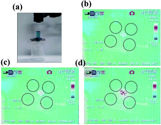 | ||
| Fig. 8 Examination of the light-controllable permeability of PNIPAM-PD/TiO2@CFC. (a) The experimental setup. The cylinder placed on top of PNIPAM-PD/TiO2@CFC was half filled with water dyed in blue. (b–d) Images of the temperature transition of the PNIPAM-PD/TiO2@CFC based on the five-hole water valve under NIR laser irradiation (images adopted from ESI Video 2†). | ||
To further demonstrate local heating of the CFC resulting from laser irradiation, an NIR camera was used to record the temperature during the experiment as showing in ESI Video 2† as well as Fig. 7b–d. The results demonstrate that the temperature of the CFC surface at the center position increased from initial temperature of 24.6 °C to 26.3 °C within 1 s, and subsequently increased to 33.8 °C within 16 s owing to direct heating by irradiation. On the other hand, little influence was observed on other holes. Fig. S7† shows the image demonstrating that the permeability of the CFC could be controlled precisely by the NIR laser.
4. Conclusion
A facile strategy inspired by mussels was proposed to graft TiO2 and thermo-responsive polymer, PNIPAM, on CFC leading to the fabrication of superhydrophobic TiO2@CFC, hydrophilic PD/TiO2@CFC and PNIPAM-PD/TiO2@CFC. It is found that biomimetic CFC with periodic superhydrophobic–hydrophilic pattern possesses extremely high fog harvesting property of 206 mg cm−2 h−1; besides, PNIPAM-PD/TiO2@CFC showed photo-thermal behavior which can be used to fabricate valves for microfluidic devices. We believe that the modified CFCs possessing distinctive wettability, temperature-responsiveness, and swelling behavior will find versatile applications including for harvesting system, smart clothes, and NIR laser-controllable valve.Conflicts of interest
There are no conflicts to declare.Acknowledgements
This work was supported by National Tsing Hua University under the contract no. 105N525CE1.References
- H. Zhu, Z. G. Guo and W. M. Liu, Chem. Commun., 2016, 52, 3863–3879 RSC.
- B. Bhushan and Y. C. Jung, Prog. Mater. Sci., 2011, 56, 1–108 CrossRef CAS.
- H. B. Zeng, N. Pesika, Y. Tian, B. X. Zhao, Y. F. Chen, M. Tirrell, K. L. Turner and J. N. Israelachvili, Langmuir, 2009, 25, 7486–7495 CrossRef CAS PubMed.
- Y. L. Liu, K. L. Ai and L. H. Lu, Chem. Rev., 2014, 114, 5057–5115 CrossRef CAS PubMed.
- H. Lee, N. F. Scherer and P. B. Messersmith, Proc. Natl. Acad. Sci. U. S. A., 2006, 103, 12999–13003 CrossRef CAS PubMed.
- Z. Y. Ma, X. Jia, J. M. Hu, Z. Y. Liu, H. Y. Wang and F. Zhou, J. Agric. Food Chem., 2013, 61, 12232–12237 CrossRef CAS PubMed.
- K. Pan, R. M. Ren, Y. Dan and B. Cao, J. Appl. Polym. Sci., 2011, 122, 2047–2053 CrossRef CAS.
- J. J. Qi, W. P. Lv, G. L. Zhang, F. B. Zhang and X. B. Fan, Polym. Chem., 2012, 3, 621–624 RSC.
- M. A. Molina, C. R. Rivarola, M. F. Broglia, D. F. Acevedo and C. A. Barbero, Soft Matter, 2012, 8, 307–310 RSC.
- D. C. Coughlan, F. P. Quilty and O. I. Corrigan, J. Controlled Release, 2004, 98, 97–114 CrossRef CAS PubMed.
- H. R. Yang, H. J. Zhu, M. M. R. M. Hendrix, N. J. H. G. M. Lousberg, G. de With, A. C. C. Esteves and J. H. Xin, Adv. Mater., 2013, 25, 1150–1154 CrossRef CAS PubMed.
- B. P. Tripathi, N. C. Dubey, F. Simon and M. Stamm, RSC Adv., 2014, 4, 34073–34083 RSC.
- Y. G. Shi, M. Y. Liu, K. Wang, F. J. Deng, Q. Wan, Q. Huang, L. H. Fu, X. Y. Zhang and Y. Wei, Polym. Chem., 2015, 6, 5876–5883 RSC.
- X. L. Jiang, Y. L. Wang and M. G. Li, Sci. Rep., 2014, 4, 6070 CrossRef CAS PubMed.
- I. You, Y. C. Seo and H. Lee, RSC Adv., 2014, 4, 10330–10333 RSC.
- J. I. Clodt, V. Filiz, S. Rangou, K. Buhr, C. Abetz, D. Hoche, J. Hahn, A. Jung and V. Abetz, Adv. Funct. Mater., 2013, 23, 731–738 CrossRef CAS.
- Y. C. Wang, L. B. Zhang, J. B. Wu, M. N. Hedhili and P. Wang, J. Mater. Chem. A, 2015, 3, 18963–18969 CAS.
- N. Graf, E. Yegen, T. Gross, A. Lippitz, W. Weigel, S. Krakert, A. Terfort and W. E. S. Unger, Surf. Sci., 2009, 603, 2849–2860 CrossRef CAS.
- L. B. Zhang, J. B. Wu, M. N. Hedhili, X. L. Yang and P. Wang, J. Mater. Chem. A, 2015, 3, 2844–2852 CAS.
- H. Bai, L. Wang, J. Ju, R. Z. Sun, Y. M. Zheng and L. Jiang, Adv. Mater., 2014, 26, 5025–5030 CrossRef CAS PubMed.
- P. F. Li, X. J. Ju, L. Y. Chu and R. Xie, Chem. Eng. Technol., 2006, 29, 1333–1339 CrossRef CAS.
- D. Kim, H. S. Lee and J. Yoon, RSC Adv., 2014, 4, 25379–25383 RSC.
Footnote |
| † Electronic supplementary information (ESI) available. See DOI: 10.1039/c7ra05869a |
| This journal is © The Royal Society of Chemistry 2017 |

