 Open Access Article
Creative Commons Attribution 3.0 Unported Licence
Trace-doped metal–organic gels with remarkably enhanced luminescence†
Xiying Feng,
Lihua Zeng,
Dianting Zou,
Zizhe Zhang,
Guihao Zhong,
Shuyin Peng,
Liping Liu,
Liuping Chen and
Jianyong Zhang *
*
Sun Yat-Sen University, Lehn Institute of Functional Materials, MOE Laboratory of Bioinorganic and Synthetic Chemistry, Guangzhou 510275, China. E-mail: zhjyong@mail.sysu.edu.cn
First published on 27th July 2017
Abstract
A novel approach has been proposed to fabricate MOF-based luminescent gel materials with trace amounts of doping in order to study the role of trace defects in metal–organic gel materials. UiO-66-based ZrBDC (BDC = 1,4-benzene dicarboxylate) gels were first prepared from Zr4+ and H2BDC under mild conditions, and subsequently trace doping (as low as 0.01 mol%) of the ZrBDC gel materials with H4TCPE (tetrakis(4-carboxyphenyl)ethylene) was achieved successfully. The resulting ZrBDC–TCPE0.01% gel material features mild synthetic conditions and retains the high porosity of parent UiO-66 gel materials. Moreover, trace doping causes a remarkable change to the luminescence properties and the gel emits blue luminescence with high quantum yield (59%). ZrBDC–TCPE0.01% shows responses with high sensitivity and selectivity for nitroaromatics (picric acid) in the aqueous phase and detects picric acid as low as parts per billion (24 ppb). The present luminescent gel materials provide new insights into developing functional metal–organic materials through trace defects, which may remarkably alter the properties of metal–organic materials.
Introduction
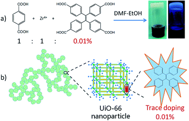
Defected materials can give rise to a large range of optical, electronic, magnetic, conductive and other physical properties. The materials properties can be tuned and optimized by controlling the defect composition. For example, in traditional inorganic luminescent materials, doping other elements into the main body is classic approach to tune the emissive performance. As a catalogue of porous materials, metal–organic frameworks (MOFs) from the self-assembly of inorganic and organic building blocks usually form highly ordered crystalline solids, and discussions about the properties of MOFs focus mainly on features revealed by the crystal structures. However, the crystal structures of MOFs may not fully relate to their physical properties, and defects or deviations from an ideally ordered crystal structure have been recently shown to significantly affect their properties.1–6 There are several methods to create defects in MOFs, including doping with another ligand or metal element into the linkers or the inorganic nodes, missing linkers or components, and partial ligand replacement or metal ion replacement.7–16 Among these methods doping has been shown to produce novel properties while maintaining the parent framework topologies,7–14,17 thus providing abundant opportunities in catalysis, sorption, magnetic, optical, conductive materials, and so on. However, all these studies focus on stoichiometric loading of defects (typically >10 mol%) and the role of trace defects has been given little regard.In the present work we propose a novel approach for fabricating MOF-based gel materials with trace-doped-enhancement luminescence. MOF-based gel materials are assembled from MOF nanoparticles, combining the advantages of MOFs and of gels.18–22 UiO-66-based ZrBDC (BDC = 1,4-benzene dicarboxylate) gel materials have been developed as new members of these materials. Subsequent trace doping (as low as 0.01 mol%) of the gel materials with tetraphenylethylene (TPE) lumiphore has been achieved (Fig. 1). The resulting materials have three features. (1) MOFs offer a platform with high surface areas, tuneable framework composition. Among them, UiO-66-type MOFs have Zr6-based robust and porous networks with high connectivity with each [Zr6(μ3-O)4(μ3-OH)4]12+ node linked to 12 carboxylates of 1,4-benzene dicarboxylate ligands,23–25 showing high thermal and chemical stability.26–29 (2) Gelation is a powerful method to prepare micro-meso-macroporous hierarchical metal–organic materials with surface and inherent defects under mild conditions.30–34 It may scale down MOF crystallites to the nanosize regime and implement hierarchical porosity to overcome diffusion limitations.18–22 (3) Materials with trace doping may be interesting because it may save expensive luminescent materials and avoid some problems caused by high doping concentration such as unstable luminescence and device aging. Additionally trace-doped materials are generally isostructural to the parent ones, thus it is easy to predict the outcome structure and the synthesis of functionalized materials becomes versatile and applicable.
Results and discussion
First, parent ZrBDC gels were prepared through reaction of 1,4-benzenedicarboxylic acid (H2BDC) with ZrCl4 in DMF–EtOH (v/v 1![[thin space (1/6-em)]](https://www.rsc.org/images/entities/char_2009.gif) :
:![[thin space (1/6-em)]](https://www.rsc.org/images/entities/char_2009.gif) 1) upon mild heating at 80 °C (Fig. S1 and Table S1†).20,21 When the molar ratio of Zr/BDC ranges from 1
1) upon mild heating at 80 °C (Fig. S1 and Table S1†).20,21 When the molar ratio of Zr/BDC ranges from 1![[thin space (1/6-em)]](https://www.rsc.org/images/entities/char_2009.gif) :
:![[thin space (1/6-em)]](https://www.rsc.org/images/entities/char_2009.gif) 1 to 2
1 to 2![[thin space (1/6-em)]](https://www.rsc.org/images/entities/char_2009.gif) :
:![[thin space (1/6-em)]](https://www.rsc.org/images/entities/char_2009.gif) 1, white opaque gels were obtained within 1–1.5 h. ZrBDC-1:1-0.15 gel, denoting the molar ratio of Zr/BDC is 1
1, white opaque gels were obtained within 1–1.5 h. ZrBDC-1:1-0.15 gel, denoting the molar ratio of Zr/BDC is 1![[thin space (1/6-em)]](https://www.rsc.org/images/entities/char_2009.gif) :
:![[thin space (1/6-em)]](https://www.rsc.org/images/entities/char_2009.gif) 1 and the concentration is 0.15 mol L−1 based on BDC, was chosen and investigated in detail. SEM investigations show that the gels have porous networked structures consisting of cross-linked particles, and TEM investigations verify that the agglomerated nanoparticles with 50–100 nm sizes are irregularly interconnected, spanning large void spaces and sustaining the gel matrix (Fig. 2a and b). PXRD was applied to establish the microstructures of the gel materials. The ZrBDC gel materials possess powder X-ray diffraction (PXRD) patterns that are remarkably consistent with that reported for the UiO-66 topology (Fig. 3).35 This implies that the gels consist of crystalline components of MOF structure, that is, an ordered 3D framework of Zr6O4(OH)4(BDC)6 that are bridged by the 1,4-benzene dicarboxylate linkers. The broadness of the diffraction peaks indicates that the MOF components in the gel are nanoparticles (71 nm for ZrBDC-1:1-0.15, as simulated by the Scherer equation), which is in agreement with the SEM and TEM observations. Therefore the present ZrBDC-1:1-0.15 gel material has a porous networked structure consisting of cross-linked UiO-66 MOF nanoparticles.
1 and the concentration is 0.15 mol L−1 based on BDC, was chosen and investigated in detail. SEM investigations show that the gels have porous networked structures consisting of cross-linked particles, and TEM investigations verify that the agglomerated nanoparticles with 50–100 nm sizes are irregularly interconnected, spanning large void spaces and sustaining the gel matrix (Fig. 2a and b). PXRD was applied to establish the microstructures of the gel materials. The ZrBDC gel materials possess powder X-ray diffraction (PXRD) patterns that are remarkably consistent with that reported for the UiO-66 topology (Fig. 3).35 This implies that the gels consist of crystalline components of MOF structure, that is, an ordered 3D framework of Zr6O4(OH)4(BDC)6 that are bridged by the 1,4-benzene dicarboxylate linkers. The broadness of the diffraction peaks indicates that the MOF components in the gel are nanoparticles (71 nm for ZrBDC-1:1-0.15, as simulated by the Scherer equation), which is in agreement with the SEM and TEM observations. Therefore the present ZrBDC-1:1-0.15 gel material has a porous networked structure consisting of cross-linked UiO-66 MOF nanoparticles.
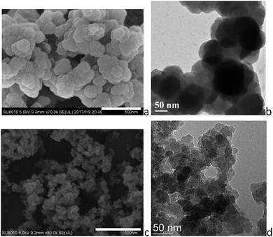 | ||
| Fig. 2 (a) SEM and (b) TEM images of ZrBDC-1:1-0.15, and (c) SEM and (d) TEM images of ZrBDC–TCPE0.01%. Scale bars represent 500 nm for SEM images. | ||
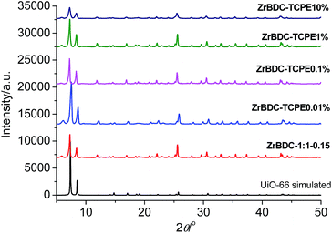 | ||
| Fig. 3 PXRD patterns of (from bottom to top) simulated UiO-66, ZrBDC-1:1-0.15, ZrBDC–TCPEx (x = 0.01, 0.1, 1, 10%) wet gels. The patterns are vertically offset for clarity. | ||
To create luminescent gels, tetraphenylethylene (TPE) lumiphore is subsequently introduced into the ZrBDC-1:1-0.15 gel via trace doping of tetrakis(4-carboxyphenyl)ethylene (H4TCPE). In this strategy TCPE is an inherent component as the organic struts for the construction of the gel matrix via coassembly of two ligands into gels. TCPE groups replace part of the 1,4-benzenedicarboxylate linkers in the gel material, creating luminescent gel materials. Additionally TPE features aggregation-induced emission (AIE) characteristics showing highly enhanced emission in the aggregate state.36 Immobilization of H4TCPE into a rigid framework may inhibit the rotation and torsion of phenyl rings, leading to increased quantum yield.37–41 ZrBDC-1:1-0.15 gel with trace doping (0.01%) of TCPE was prepared, synthetically 0.01% equivalent of H4TCPE with respect of H2BDC was used to prepare metal–organic gels, and the sample is denoted as ZrBDC–TCPE0.01% (Fig. 1). For comparison ZrBDC–TCPEx (x = 0.1, 1, 10%) gels were also prepared (Fig. S1†). In order to characterize the porosity, the solvent in the wet gels was removed by centrifugation and exchanged with ethanol, and the resulting materials were dried by subcritical CO2(l) to obtain dried materials as crushed solid.
SEM and TEM reveal that the introducing of TCPE does not affect the morphology significantly, showing similar porous structures with cross-linked nanoparticles (Fig. 2c, d and S2–S4†). In comparison ZrBDC–TCPE0.01% consists of smaller nanoparticles with ca. 20–50 nm size. The gels give well-resolved PXRD patterns with salient peaks that precisely match the simulated patterns of single-crystal UiO-66, indicating that the crystallinity of UiO-66 is maintained (Fig. 3). The crystallite size of is ca. 41 nm for ZrBDC–TCPE0.01%, as simulated by the Scherer equation. The smaller nanoparticles may be attributed to the presence of increasing surface and inherent defects in the trace-doped materials.
ZrBDC–TCPE0.01% gel was also characterized by other analytical techniques including FT-IR, EDX and XPS (Fig. S5–S11†), but no difference could be identified as expected due to the trace presence of TCPE. FT-IR spectra account for the presence of carboxylate in the metal coordination sphere, as evidenced by the C![[double bond, length as m-dash]](https://www.rsc.org/images/entities/char_e001.gif) O asymmetric stretching at around 1580 cm−1. Elemental composition analysis by energy dispersive X-ray spectroscopy (EDX) reveals that trace of Cl was present as well in the gels which originate from the precursors. X-ray photoelectron spectroscopy (XPS) analysis shows that the Zr 3d3/2 and 3d5/2 binding energies are 185.2 and 182.8 eV, respectively, confirming the presence of highly oxidized tetravalent zirconium.
O asymmetric stretching at around 1580 cm−1. Elemental composition analysis by energy dispersive X-ray spectroscopy (EDX) reveals that trace of Cl was present as well in the gels which originate from the precursors. X-ray photoelectron spectroscopy (XPS) analysis shows that the Zr 3d3/2 and 3d5/2 binding energies are 185.2 and 182.8 eV, respectively, confirming the presence of highly oxidized tetravalent zirconium.
Thermogravimetric analysis (TGA) profiles of ZrBDC-1:1-0.15 and ZrBDC–TCPE0.01% exhibit continuous weight loss of 56%, related to the removal of moisture, free solvent and ligand and they may remain thermally stable up to ca. 550 °C (Fig. S12†). In the TGA profile of ZrBDC-1:1-0.15, a weight loss from 68 wt% to 44 wt% between 500 and 600 °C means that the as-synthesized material is defective, exhibiting about 8 BDC ligands per Zr6O4(OH)4 cluster. In the TGA profile of ZrBDC–TCPE0.01%, the weight loss from 71 wt% to 46 wt% between 500 and 600 °C is consistent with a BDC![[thin space (1/6-em)]](https://www.rsc.org/images/entities/char_2009.gif) :
:![[thin space (1/6-em)]](https://www.rsc.org/images/entities/char_2009.gif) Zr6 ratio of 8, in line with similar linker deficiency.42 Such defective UiO-66 materials43–46 may be produced because the present synthesis temperature was low.47
Zr6 ratio of 8, in line with similar linker deficiency.42 Such defective UiO-66 materials43–46 may be produced because the present synthesis temperature was low.47
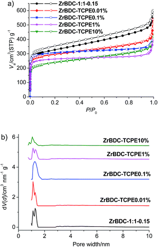
To evaluate the porosity, N2 adsorption–desorption isotherms were collected for the dried materials (Fig. 4 and Table S2†). For ZrBDC-1:1-0.15, the BET surface area is 1140–1236 m2 g−1 and the total pore volume is 0.929–1.107 cm3 g−1 (two parallel measurements). Its microporosity nature was indicated by rapid gas sorption at low relative pressure (P/P0 < 0.05). Pore size distributions obtained by nonlocal density functional theory (NLDFT) show main pore size centred at ca. 1.11 and 1.27 nm, interpreted as octahedral cages in the pristine UiO-66 structure as well as defect-related regions.48 The trace doping with TCPE (0.01%, 0.1%) does not show much effect on the porosity of gel materials. For ZrBDC–TCPE0.01%, the BET surface area is 1145–1280 m2 g−1 and the total pore volume is 0.598–0.832 cm3 g−1 (two parallel measurements). Additionally the pore size does not change greatly with main pore size centred at ca. 1.11 and 1.27 nm. This is consistent with the reported data with only 8 linkers per node44 and the above TG data. However, the BET surface areas (1044–901 m2 g−1) and pore volumes (0.613–0.682 cm3 g−1) decrease with high doping concentration of TCPE (1%, 10%).
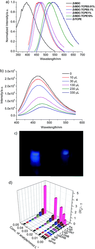
The photoluminescence property of ZrBDC–TCPEx gel materials synthesized with various doping concentration (0.01–10% of TCPE with respect to BDC) was examined (Fig. 5a, S13 and Table S3†). ZrBDC-1:1-0.15 gel is nearly weakly emissive with an emission band at about 498 nm and a fluorescence quantum yield of 14% in gel state. The fluorescence spectra of ZrBDC–TCPEx gels display an obvious blue shift and the corresponding emission efficiency increases remarkably. In contrast to ZrBDC-1:1-0.15 gel, ZrBDC–TCPE0.01% is highly emissive. The fluorescence is blue-shifted with an emission maximum at 461 nm, which originate from the ligand-based π–π* transition. The fluorescence efficiency of ZrBDC–TCPE0.01% is as high as 59%, much higher than that of the parent gel. The time-resolved emission-decay behaviours show that the weighted mean lifetime is 3.32 ns for ZrBDC–TCPE0.01%.
The emission peak wavelengths for the ZrBDC–TCPEx gels dispersed in water range from 461 nm (x = 0.01%) to 521 nm (x = 10%). With increasing content of TCPE, the emission wavelengths presented a red-shift. The emission of the ZrBDC–TCPEx gels with higher content of TCPE move closer to that of the ZrTCPE gel (λem = 540 nm). Thus the emission of ZrBDC–TCPE0.01% mainly ascribe to the homogeneous distribution of TCPE in the framework. The porous network of ZrBDC UiO-66 nanoparticles sterically inhibits the TPE fluorophores from approaching each other and prevents the aggregation of TCPE molecules. This leads to the blue-shifted emission of ZrBDC–TCPE0.01% in comparison with ZrTCPE. The blue shift in the emission is obvious when the doping concentration is low.
The unique porosity and the fluorescence of ZrBDC–TCPEx gels prompted us to explore their potential application as fluorescent sensors for nitroexplosives. The open framework structure of ZrBDC–TCPEx gels with high surface area and large pore windows may facilitate guest diffusion across the frameworks and easily interact with active lumiphore sites. Herein picric acid (PA) was used as a model nitroexplosive (Scheme S1†). Fluorescence quenching titrations with various PA concentrations were conducted at room temperature in aqueous solution because aqueous-phase detection is preferred for probing of nitro explosives in soil or groundwater.49 The gels were readily dispersed in water with a concentration of 10 g L−1 for detection. The fluorescent intensity gradually decreases with the addition of PA into ZrBDC–TCPE0.01% (Fig. 5b, c and S14†). The Stern–Volmer (SV) equation of the relative fluorescence intensity vs. PA concentration in aqueous solution is I0/I = KSV[A] + 1, where I0 and I are the photoluminescence intensities before and after addition of the analyte, respectively, and [A] is the molar concentration of the analyte. KSV is the quenching constant (L mol−1). The relative fluorescence intensity is linear with the concentration suggesting the quenching is mainly diffusion-limited. The quenching constant for PA is 2.91 × 10⁵ L mol−1 in the low concentration range (0–0.53 mol L−1) (R2 = 0.9962), which is remarkably higher than that of a closely related TPE-modified Zr-MOF (2.8 × 10⁴ L mol−1),50 lying amongst the highest of the known luminescent MOF-based sensors.51–53 The limit of detection (LOD) is calculated by the fluorescence quenching data using the 3σ/slope criteria using the equation LOD = 3σ/m, where σ is the standard deviation of blank measurements, and m is the slope between the fluorescence intensity and analyte concentration. The LOD is 1.05 × 10⁻⁷ mol L−1 (24 ppb) for ZrBDC–TCPE0.01%. Interestingly, both the quenching constant and the LOD decrease when the doping concentration of TCPE is higher for the ZrBDC–TCPEx gels (Fig. S15 and S16†). The quenching constant is 1.82 × 10⁵ and 5.64 × 10⁴ L mol−1 and the LOD is 1.98 × 10⁻⁷ (45 ppb) and 5.25 × 10⁻⁷ (120 ppb) for ZrBDC–TCPE0.1% and ZrBDC–TCPE1%, respectively. Therefore, the present gel material with trace doping of TCPE greatly enhances fluorescence response efficiency and demonstrates the potential as a novel type of highly sensitive sensors for PA in aqueous phase.
Fluorescence quenching titrations were also performed with nitroaromatic compounds with similar chemical structures such as 2,6-dinitrophenol (2,6-DNP), 1,3-dinitrobenzene (1,3-DNB), 4-nitrophenol (4-NP), 2-nitrophenol (2-NP) and nitrobenzene (NB), and nitro-aliphatic compounds such as 2,3-dimethyl-2,3-dinitrobutane (DMDNB), 1-nitropropane (NProp) and nitromethane (NM) (Scheme S1†). In a typically designed experimental protocol, the fluorescence spectrum for ZrBDC–TCPE0.01% dispersed in water was monitored upon the incremental addition of an aqueous solution of nitroaromatic compounds. Different extents of fluorescence quenching take place upon the addition of the same amount of various analytes (400 μL of 0.1 mM) (Fig. 5d and S17–S25†). The fluorescence quenching efficiencies of various analytes are calculated using the equation (I0 − I)/I0 × 100%, where I0 and I are the fluorescence intensities of ZrBDC–TCPE0.01% before and after the addition of the analytes. The fluorescence quenching efficiencies are in the order, PA (83.1%) ≫ 4-NP (51.8%) > 2,6-DNT (41.2%) > 2-NP (30.0%) > 1,3-DNB (15.6%) > DMDNB (12.3%) > NB (10.0%) > NM (8.6%) > 1-NProp (6.6%). It suggests that PA shows significant and sensitive fluorescence quenching, while other nitroaromatic compounds with similar chemical structures have much lower fluorescence quenching efficiencies.
The quenching mechanism may be proposed as follow. The tested analytes have suitable sizes (e.g., PA 5.0 × 6.2 × 7.1 Å) to enter the pores of gel nanoparticles.54 The selective fluorescence quenching for PA may be attributed to energy transfer of the excited-state electron of ZrBDC–TCPE0.01% to the electron-deficient PA molecule with its electron-withdrawing –NO2 group. The absorption bands of the analyte PA display considerable overlap with the emission spectra of ZrBDC–TCPE0.01%, while nearly absent overlap in the cases of other nitro compounds (Fig. S26†). Resonance energy transfer can effectively occur from the fluorophore to non-emitting analytes. In addition, the fluorescence emission decays instantly upon the addition of PA solution into ZrBDC–TCPE1% and maintain an equilibration afterwards (Fig. S26†). The decay time is short to fall in the data collection time of the fluorometer (<1 min). It suggests facile diffusion (mass transfer) of PA across the porous gel network of ZrBDC–TCPE0.01%.
Conclusions
In summary, we develop a facile and simple gelation approach for fabricating highly luminescent UiO-66 MOF based ZrBDC materials with trace doping of TPE lumiphor (as low as 0.01%). TCPE groups replace part of the BDC linkers in the parent gel material and the TPE chromophore is incorporated dilutely into the UiO-66 MOF nanoparticle matrix, creating highly luminescent materials. The gel material ZrBDC–TCPE0.01% displays the merits of MOFs, gels and trace doping. It consists of interconnected highly porous MOF nanoparticles having the framework structure of UiO-66 and the unique feature of trace occupied TCPE sites (0.01%), causing large change to its luminescent properties. The aqueous dispersion of ZrBDC–TCPE0.01% gel emits blue luminescence with high quantum yield. It shows ability to selectively identify the presence of a trace quantity of nitroaromatic explosive in aqueous phase through fluorescence quenching, attractive in virtue of high sensitivity, and rapid response time. These results demonstrate that trace defective sites within metal–organic materials can significantly alter the properties, showing that this class of gel materials and MOFs can serve as a tunable porous platform for novel applications. The method may be utilized for the design of functional porous materials which incorporate a fraction of functional sites into a known phase built from simpler building blocks to avoid tedious synthesis.Acknowledgements
We gratefully acknowledge the NSFC (51573216), the NSF of Guangdong Province (S2013030013474) and the FRF for the Central Universities (16lgjc66) for financial support.Notes and references
- T. D. Bennett, A. K. Cheetham, A. H. Fuchs and F.-X. Coudert, Nat. Chem., 2017, 9, 11–16 CrossRef CAS PubMed.
- Z. Fang, B. Bueken, D. E. De Vos and R. A. Fischer, Angew. Chem., Int. Ed., 2015, 54, 7234–7254 CrossRef CAS PubMed.
- H. Furukawa, U. Müller and O. M. Yaghi, Angew. Chem., Int. Ed., 2015, 54, 3417–3430 CrossRef CAS PubMed.
- D. S. Sholl and R. P. Lively, J. Phys. Chem. Lett., 2015, 6, 3437–3444 CrossRef CAS PubMed.
- A. Dhakshinamoorthy, A. M. Asiri and H. Garcia, Catal. Sci. Technol., 2016, 6, 5238–5261 CAS.
- J. Canivet, M. Vandichel and D. Farrusseng, Dalton Trans., 2016, 45, 4090–4099 RSC.
- S. S. Han and W. A. Goddard III, J. Am. Chem. Soc., 2007, 129, 8422–8423 CrossRef CAS PubMed.
- Y. Cui, H. Xu, Y. Yue, Z. Guo, J. Yu, Z. Chen, J. Gao, Y. Yang, G. Qian and B. Chen, J. Am. Chem. Soc., 2012, 134, 3979–3982 CrossRef CAS PubMed.
- X. Zhang, B. Li, H. Ma, L. Zhang and H. Zhao, ACS Appl. Mater. Interfaces, 2016, 8, 17389–17394 CAS.
- R.-Y. Chen, D. Tian, Y.-W. Li, Y.-B. Lv, H.-W. Sun, Z. Chang and X.-H. Bu, RSC Adv., 2015, 5, 24655–24660 RSC.
- F. Vermoortele, B. Bueken, G. Le Bars, B. V. de Voorde, M. Vandichel, K. Houthoofd, A. Vimont, M. Daturi, M. Waroquier, V. Van Spey-broeck, C. Kirschhock and D. E. De Vos, J. Am. Chem. Soc., 2013, 135, 11465–11468 CrossRef CAS PubMed.
- C. Wang, Z. Xie, K. E. deKrafft and W. Lin, J. Am. Chem. Soc., 2011, 133, 13445–13454 CrossRef CAS PubMed.
- C. Wang, D. Liu, Z. Xie and W. Lin, Inorg. Chem., 2014, 53, 1331–1338 CrossRef CAS PubMed.
- S. Marx, W. Kleist and A. Baiker, J. Catal., 2011, 281, 76–87 CrossRef CAS.
- Z. Fang, J. P. Dürholt, M. Kauer, W. Zhang, C. Lochenie, B. Jee, B. Albada, N. Metzler-Nolte, A. Pöppl, B. Weber, M. Muhler, Y. Wang, R. Schmid and R. A. Fischer, J. Am. Chem. Soc., 2014, 136, 9627–9636 CrossRef CAS PubMed.
- J. Park, Z. U. Wang, L.-B. Sun, Y.-P. Chen and H.-C. Zhou, J. Am. Chem. Soc., 2012, 134, 20110–20116 CrossRef CAS PubMed.
- P. Falcaro and S. Furukawa, Angew. Chem., Int. Ed., 2012, 51, 8431–8433 CrossRef CAS PubMed.
- A. K. Chaudhari, I. Han and J.-C. Tan, Adv. Mater., 2015, 27, 4438–4446 CrossRef CAS PubMed.
- J. J. Marrero-Telladoa and D. D. Díaz, CrystEngComm, 2015, 17, 7978–7985 RSC.
- L. Li, S. Xiang, S. Cao, J. Zhang, G. Ouyang, L. Chen and C. Y. Su, Nat. Commun., 2013, 4, 1774–1782 CrossRef PubMed.
- L. Liu, J. Zhang, H. Fang, L. Chen and C.-Y. Su, Chem.–Asian J., 2016, 11, 2278–2283 CrossRef CAS PubMed.
- Q. Wei and S. L. James, Chem. Commun., 2005, 1555–1556 RSC.
- J. H. Cavka, S. Jakobsen, U. Olsbye, N. Guillou, C. Lamberti, S. Bordiga and K. P. Lillerud, J. Am. Chem. Soc., 2008, 130, 13850–13851 CrossRef PubMed.
- J. B. DeCoste, G. W. Peterson, B. J. Schindler, K. L. Killops, M. A. Broweb and J. J. Mahle, J. Mater. Chem. A, 2013, 1, 11922–11932 CAS.
- M. Kandiah, M. H. Nilsen, S. Usseglio, S. Jakobsen, U. Olsbye, M. Tilset, C. Larabi, E. A. Quadrelli, F. Bonino and K. P. Lillerud, Chem. Mater., 2010, 22, 6632–6640 CrossRef CAS.
- G. E. Cmarik, M. Kim, S. M. Cohen and K. S. Walton, Langmuir, 2012, 28, 15606–15613 CrossRef CAS PubMed.
- M. J. Katz, S.-Y. Moon, J. E. Mondloch, M. H. Beyzavi, C. J. Stephenson, J. T. Hupp and O. K. Farha, Chem. Sci., 2015, 6, 2286–2291 RSC.
- D. Yang, S. O. Odoh, T. C. Wang, O. K. Farha, J. T. Hupp, C. J. Cramer, L. Gagliardi and B. C. Gates, J. Am. Chem. Soc., 2015, 137, 7391–7396 CrossRef CAS PubMed.
- H. G. T. Nguyen, N. M. Schweitzer, C.-Y. Chang, T. L. Drake, M. C. So, P. C. Stair, O. K. Farha, J. T. Hupp and S. T. Nguyen, ACS Catal., 2014, 4, 2496–2500 CrossRef CAS.
- P. Dastidar, S. Ganguly and K. Sarkar, Chem.–Asian J., 2016, 11, 2484–2498 CrossRef CAS PubMed.
- M.-O. M. Piepenbrock, G. O. Lloyd, N. Clarke and J. W. Steed, Chem. Rev., 2010, 110, 1960–2004 CrossRef CAS PubMed.
- D. Vallejo-Sánchez, P. Amo-Ochoa, G. Beobide, O. Castillo, M. Fröba, F. Hoffmann, A. Luque, P. Ocón and S. Pérez-Yáñez, Adv. Funct. Mater., 2017, 1605448 CrossRef.
- A. Mahmood, W. Xia, N. Mahmood, Q. Wang and R. Zou, Sci. Rep., 2015, 5, 10556 CrossRef PubMed.
- P. Sutar and T. K. Maji, Chem. Commun., 2016, 52, 8055–8074 RSC.
- S. J. Garibay and S. M. Cohen, Chem. Commun., 2010, 46, 7700–7702 RSC.
- Y. Dong, J. W. Y. Lam, A. Qin, J. Liu, Z. Li and B. Z. Tang, Appl. Phys. Lett., 2007, 91, 011111 CrossRef.
- N. B. Shustova, B. D. McCarthy and M. Dincǎ, J. Am. Chem. Soc., 2011, 133, 20126–20129 CrossRef CAS PubMed.
- Z. Wei, Z.-Y. Gu, R. K. Arvapally, Y.-P. Chen, R. N. McDougald, J. F. Ivy, A. A. Yakovenko, D. Feng, M. A. Omary and H.-C. Zhou, J. Am. Chem. Soc., 2014, 136, 8269–8276 CrossRef CAS PubMed.
- Z. Hu, G. Huang, W. P. Lustig, F. Wang, H. Wang, S. J. Teat, D. Banerjee, D. Zhang and J. Li, Chem. Commun., 2015, 51, 3045–3048 RSC.
- J. Feng, L. Zeng, K. Chen, H. Fang, J. Zhang, Z. Chi and C. Y. Su, Langmuir, 2016, 32, 12184–12189 CrossRef CAS PubMed.
- J. Zhang, Q. Yang, Y. Zhu, H. Liu, Z. Chi and C. Y. Su, Dalton Trans., 2014, 43, 15785–19790 RSC.
- L. Valenzano, B. Civalleri, S. Chavan, S. Bordiga, M. H. Nilsen, S. Jakobsen, K. P. Lillerud and C. Lamberti, Chem. Mater., 2011, 23, 1700–1718 CrossRef CAS.
- H. Wu, Y. Chua, V. Krungleviciute, M. Tyagi, P. Chen, T. Yildirim and W. Zhou, J. Am. Chem. Soc., 2013, 135, 10525–10532 CrossRef CAS PubMed.
- M. J. Katz, Z. J. Brown, Y. J. Colón, P. W. Siu, K. A. Scheidt, R. Q. Snurr, J. T. Hupp and O. K. Farha, Chem. Commun., 2013, 49, 9449–9451 RSC.
- L. Sarkisov and A. Harrison, Mol. Simul., 2011, 37, 1248–1257 CrossRef CAS.
- F. Vermoortele, B. Bueken, G. Le Bars, B. Van de Voorde, M. Vandichel, K. Houthoofd, A. Vimont, M. Daturi, M. Waroquier, V. Van Speybroeck, C. Kirschhock and D. E. De Vos, J. Am. Chem. Soc., 2013, 135, 11465–11468 CrossRef CAS PubMed.
- G. C. Shearer, S. Chavan, J. Ethiraj, J. G. Vitillo, S. Svelle, U. Olsbye, C. Lamberti, S. Bordiga and K. P. Lillerud, Chem. Mater., 2014, 26, 4068–4071 CrossRef CAS.
- W. Liang, C. J. Coghlan, F. Ragon, M. Rubio-Martinez, D. M. D'Alessandro and R. Babarao, Dalton Trans., 2016, 45, 4496–4500 RSC.
- J. Yang, Z. Wang, K. Hu, Y. Li, J. Feng, J. Shi and J. Gu, ACS Appl. Mater. Interfaces, 2015, 7, 11956–11964 CAS.
- Q.-Y. Li, Z. Ma, W.-Q. Zhang, J.-L. Xu, W. Wei, H. Lu, X. Zhao and X.-J. Wang, Chem. Commun., 2016, 52, 11284–11287 RSC.
- B. Joarder, A. V. Desai, P. Samanta, S. Mukherjee and S. K. Ghosh, Chem.–Eur. J., 2015, 21, 965–969 CrossRef CAS PubMed.
- Y. Rachuri, B. Parmar, K. K. Bisht and E. Suresh, Dalton Trans., 2016, 45, 7881–7892 RSC.
- Z. Hu, B. J. Deibert and J. Li, Chem. Soc. Rev., 2014, 43, 5815–5840 RSC.
- S. S. Nagarkar, B. Joarder, A. K. Chaudhari, S. Mukherjee and S. K. Ghosh, Angew. Chem., Int. Ed., 2013, 52, 2881–2885 CrossRef CAS PubMed.
Footnote |
| † Electronic supplementary information (ESI) available: Experimental details, photos, SEM and TEM images, EDX, IR, XPS spectra, TGA and luminescence data. See DOI: 10.1039/c7ra05783k |
| This journal is © The Royal Society of Chemistry 2017 |

