 Open Access Article
Formation mechanism of multilayer TiO2 nanotubes in HBF4 electrolyte
Shaoyu Zhangab,
Mengshi Yua,
Liming Xub,
Siwei Zhaoa,
Jianfei Chea and
Xufei Zhu *a
*a
aKey Laboratory of Soft Chemistry and Functional Materials of Education Ministry, Nanjing University of Science and Technology, Nanjing 210094, China. E-mail: zhuxufei.njust@163.com
bJiangsu Urban and Rural Construction College, Changzhou 213147, China
First published on 3rd July 2017
Abstract
Multilayer anodic TiO2 nanotubes are first fabricated in HBF4-containing electrolyte by a one-step galvanostatic anodization. These nanotubes demonstrate unique A-shaped sidewalls, which are different from the traditional V-shaped nanotubes formed in NH4F-containing electrolyte. Further, the formation mechanism of the multilayer TiO2 nanotubes is proposed. During the anodizing process, the total anodizing current could be separated into ionic current and electronic current. The oxygen bubbles, induced by the electronic current, play a significant role in shaping the nanotube architectures. The bottoms of TiO2 nanotubes could be broadened under the pressure of oxygen bubbles. Thus the wall at the bottom of the nanotube becomes thinner. When the pressure of oxygen bubbles reaches a certain value, it will break the sidewalls of the nanotubes, resulting in the formation of the A-shaped sidewalls of TiO2 nanotubes. However, in NH4F-containing electrolyte, the oxygen bubbles escape from the top of nanotubes, and then the V-shaped sidewall thickness profiles of TiO2 nanotubes are formed. Owing to the inflating effect of oxygen bubbles on the nanotube walls, the whole TiO2 nanotube layer is finally divided into nanotube multilayers in HBF4-containing electrolyte.
Introduction
In recent years, anodic TiO2 nanotubes have received increasing attention due to their various applications.1–5 The most widely used electrolytes are F−-containing electrolytes.6–9 Macak et al.7 indicated that the formation of a soluble complex [TiF6]2− gives rise to oxide dissolution during formation of anodic TiO2 nanotubes. The growth of anodic TiO2 nanotubes is considered to be as a result of the equilibrium between oxide formation and oxide dissolution. The corresponding theory is called field-assisted dissolution mechanism.7–9However, the F− ion is highly aggressive and restricts the length of TiO2 nanotubes to a few micrometers.10,11 Furthermore, the field-assisted dissolution mechanism, which is based on the dissolution effect of F− ions, is doubted because researchers have found that anodic TiO2 nanotubes could be formed in F−-free electrolytes, such as sulfuric acid (H2SO4) electrolyte,12 silver nitrate (AgNO3) electrolyte13 and nitric acid (HNO3) electrolyte.14 In 2015, Hebert et al.15 also indicated that oxide dissolution rates are in fact very small during anodization. In 2012, Yang et al.16–18 elucidated the variation of the anodizing current versus time based on an electronic current and oxygen bubble model. They indicated that the total anodizing current consists of ionic current and electronic current during anodization of Ti.16–18 Ionic current is used to form oxide while the electronic current gives rise to the evolution of oxygen bubbles. Oxygen bubbles act as moulds during oxide growth.16–18 Therefore, newly formed oxide flows around these oxygen bubbles and forms anodic TiO2 nanotubes.16–19 Otherwise, the introduction of new electrolyte is helpful for exploiting new architectures and understanding the formation mechanism of anodic TiO2 nanotubes. Although anodic TiO2 nanotubes have been obtained in HBF4-containing electrolyte, none novel architecture of anodic TiO2 nanotube has been reported. There are few papers reporting forming mechanism of anodic TiO2 nanotubes in HBF4-containing electrolyte.20
Anodic TiO2 nanotubes are usually obtained under potentiostatic conditions. Anodizing voltage is generally considered as one of the key influence factors of tube diameter, interpore spacing and barrier layer thickness.20–23 Galvanostatic anodization is not commonly employed for several reasons including: (a) galvanostatic anodization demands a more accurate control of all experimental factors (area, temperature, hydrodynamics) than potentiostatic anodization,24 (b) voltage may change with time and fluctuate, and thus it is difficult to control tube diameter,25 (c) oxide layer is easy to breakdown at high anodizing current. However, Zhang et al.26 indicated that constant current condition is good for quantitative studies of forming mechanism of anodic TiO2 nanotubes. They put forward an equation between nanotube length and anodizing current.26
Multilayer TiO2 nanotubes have been prepared in F−-containing electrolyte by several groups. There are bamboo-type nanotubes,27 Y-branched nanotubes28 and reverse Y-branched nanotubes.29,30 These nanotubes have unique performances, such as improvement of dye loading ability for dye-sensitized solar cells.30 However, multilayer TiO2 nanotubes formed in HBF4-containing electrolyte have not been reported. In the present work, we compare anodic TiO2 nanotubes formed in different electrolytes. Novel multilayer TiO2 nanotubes were formed in HBF4-containing electrolyte, while a nanotube single layer was formed in NH4F-containing electrolyte. Moreover, TiO2 nanotubes formed in HBF4-containing electrolyte show an A-shaped sidewall thickness profile, while nanotubes formed in HBF4-containing electrolyte show a V-shaped thickness profile. The A-shaped sidewall thickness profile is hardly to be explained by tradition field-assisted dissolution mechanism. Thus we proposed a new forming mechanism of the multilayer TiO2 nanotubes from the perspective of electronic current. The present results may facilitate the development of new electrolytes for preparing anodic TiO2 nanotubes with various architectures, and also promote the understanding of the forming mechanism.
Experimental details
TiO2 nanotubes were formed by anodizing of Ti foils. Prior to the anodization, the commercial titanium foils (100 μm thick, purity 99.5%, Shanghai Shangmu Technology Co. Ltd.) were polished in a mixture solution of HF (≥40%), HNO3 (65–68%) and deionized water (1![[thin space (1/6-em)]](https://www.rsc.org/images/entities/char_2009.gif) :
:![[thin space (1/6-em)]](https://www.rsc.org/images/entities/char_2009.gif) 1
1![[thin space (1/6-em)]](https://www.rsc.org/images/entities/char_2009.gif) :
:![[thin space (1/6-em)]](https://www.rsc.org/images/entities/char_2009.gif) 2 in volume) for about 10 s, followed by dipping them into deionized water, and dried in the air. The polished Ti foils were then anodized in a two electrodes cell. A current density of 10 mA cm−2 was applied between a Ti anode and a Pt cathode. Anodizing experiments were carried out at room temperature (∼20 °C) for 15 minutes with stirring of the electrolyte. After anodizations, samples were rinsed with water and dried in air.
2 in volume) for about 10 s, followed by dipping them into deionized water, and dried in the air. The polished Ti foils were then anodized in a two electrodes cell. A current density of 10 mA cm−2 was applied between a Ti anode and a Pt cathode. Anodizing experiments were carried out at room temperature (∼20 °C) for 15 minutes with stirring of the electrolyte. After anodizations, samples were rinsed with water and dried in air.
The anodization was carried out in ethylene glycol electrolyte with 0.015 M (1.18 wt%) HBF4 and 2 wt% H2O (called HBF4-containing electrolyte). For comparison, anodization of Ti foil in NH4F-containing electrolyte was studied. NH4F-Containing electrolyte was ethylene glycol solution containing 0.06 M NH4F and 2 wt% H2O. Hence, the concentrations of fluorine in two electrolytes are equal.
The voltage–time curves were recorded automatically by a computer system. Morphologies of both samples were characterized by field-emission SEM (FESEM, Hitachi S-4800 II and Zeiss Supra 55). Nanotube lengths and diameters were all measured directly on the FESEM.
Results and discussion
Multilayer TiO2 nanotubes formed in HBF4-containing electrolyte
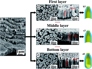
Fig. 1 shows the multilayer TiO2 nanotubes formed in HBF4-containing electrolyte, which are composed of eight TiO2 nanotube layers (Fig. 1a). Neighboring nanotubes in all layers are separated by gaps (Fig. 1b1–d1). The thickness of each layer is about 360 nm (Fig. 1b2–d2). The outer diameters of nanotubes in the first layer are approximately 90 nm (Fig. 1b2) while outer diameters of nanotubes in middle layer and bottom layer are approximately 72 nm (Fig. 1c2) and 80 nm (Fig. 1d2), respectively. Nanotubes in the first layer and middle layer have through-holes (Fig. 1b2 and c2), while nanotubes in the bottom layer are sealed at bottom by the underlying barrier layer (Fig. d2). In the first layer and middle layer, nanotube walls at the bottom are extremely thin (Fig. 1b2 and c2). Therefore, inner diameters are close to outer diameters at the bottom of nanotubes in the first layer and middle layer. However, inner diameters at the top of nanotubes in the first layer, middle layer and bottom layer are only a few nano meters (Fig. 1b1–d1). Gaps between nanotubes are larger at the top than that at the bottom in first layer, middle layer and bottom layer.Fig. 2 demonstrates the difference between nanotubes obtained in NH4F-containing electrolyte and HBF4-containing electrolyte. Nanotubes formed in HBF4-containing electrolyte show an A-shaped sidewall thickness profile, while nanotubes formed in NH4F-containing electrolyte show a V-shaped sidewall thickness profile. In traditional NH4F-containing electrolyte, ordered TiO2 nanotubes can be formed and the top nanotube surface is a porous plane. As Kowalski et al.31 indicated, the dissolution of oxide would form gaps between pores. However, there are no gaps between pores on the top surface (Fig. 2a). Therefore, the oxide dissolution on the surface is negligible. This result is consistent with the previously reported work by Çapraz et al.15 The cross-sectional SEM images of nanotubes formed in NH4F-containing electrolyte show perfectly straight and densely packed arrays of TiO2 nanotubes and the nanotubes are vertically aligned to the Ti substrate. Their outer diameters are approximately 160 nm (Fig. 2b). The inner diameter of the nanotubes is larger on the top (∼60 nm, Fig. 2a) than that at the bottom (∼45 nm, Fig. 2b). Thus, TiO2 nanotubes formed in NH4F-containing electrolyte show a V-shaped structure26,32 in their thickness (Fig. 2b), in agreement with previous reports.26,32 For TiO2 nanotubes formed in HBF4-containing electrolyte, the inner diameter on the top is much smaller than that at the bottom as shown in Fig. 2c and d. As a result, TiO2 nanotubes formed in HBF4-containing electrolyte show an A-shaped structure.
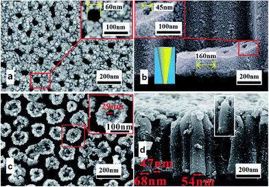 | ||
| Fig. 2 (a) and (b) FESEM images of the V-shaped TiO2 nanotubes formed in NH4F-containing electrolyte. (c) and (d) FESEM images of the A-shaped TiO2 nanotubes formed in HBF4-containing electrolyte. | ||
Forming mechanism of multilayer anodic TiO2 nanotubes
Researchers have presented several growth mechanisms for anodic TiO2 nanotubes.25,26,34 Among these mechanisms, the generally accepted mechanism is field-assisted dissolution mechanism. According to field-assisted dissolution mechanism, growth of TiO2 nanotubes can be ascribed to the dynamic equilibrium between growth (eqn (1)–(3)) and dissolution processes (eqn (4)) of oxide.21,22,35–38| Ti4+ + 2H2O → TiO2 + 4H+ | (1) |
| Ti4+ + 2O2− → TiO2 | (2) |
| Ti4+ + 4OH− → TiO2 + 2H2O | (3) |
| TiO2 + 6F− + 4H+ → [TiF6]2− + 2H2O | (4) |
Based on the traditional field-assisted dissolution mechanism, the inner diameter of nanotube mainly depends on the exposure to electrolyte due to the presence of chemical dissolution.32,33 Long time exposition to fluorine containing electrolyte results in continuous thinning of the tube walls. TiO2 nanotubes on the top are easier to be exposed to the electrolyte for longer time than those at the bottom. Thus, nanotube wall near the top ought to be thinner than that near the bottom and TiO2 nanotubes formed in NH4F-containing electrolyte show a V-shaped structure. In other words, A-shape profile (Fig. 1b3–d3) could not be formed by chemical dissolution of formed TiO2. Hence, the A-shaped sidewall thickness profile of nanotubes formed in HBF4-containing electrolyte could hardly be explained by traditional field-assisted dissolution mechanism.
Moreover, the chemical dissolution of nanotube walls is continuous. If the multilayer TiO2 nanotubes are formed by field-assisted dissolution process, what is the reason for periodically dissolution of oxide between layers? Taveira et al.25 obtained two-layer TiO2 nanotubes on titanium under galvanostatic condition. They suggested that big voltage oscillations triggered a detachment of the upper layer from the lower one.25 The reason for voltage oscillations is still unclear. But there was no distinct voltage oscillation during the anodization in HBF4-containing electrolyte, therefore, the multilayer TiO2 nanotubes were not formed by voltage oscillations.
As indicated above, the formation of nanotubes with A-shape profile in HBF4-containing electrolyte cannot be attributed to field-assisted dissolution effect of F−. Although the BF4− could decompose to BF3 and F− under high electric field (eqn (5)),39 field-assisted dissolution effect is not crucial for the formation of multilayer TiO2 nanotubes.
| BF4− → BF3 + F− | (5) |
According to previous works, the formation of TiO2 nanotube is attributed to the flow of formed oxide around oxygen bubbles. Total anodizing current is composed of ionic current and electronic current.16,19,40–43 Ionic current is used to form oxide while electronic current is used to form oxygen bubbles.16,19,40–43 Nanotubes are formed by the combined effect of oxide formation and oxygen bubble expansion.16,19,40–43
Fig. 3 shows the measured voltage–time curves in HBF4-containing electrolyte and NH4F-containing electrolyte at same anodizing current. However, the equilibrium voltage in HBF4-containing electrolyte is approximately twice as high as that in NH4F-containing electrolyte. Voltage oscillations during anodization in HBF4-containing electrolyte are more obvious than that in NH4F-containing electrolyte.
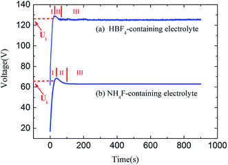 | ||
| Fig. 3 Voltage–time curves during Ti anodizations in (a) HBF4-containing electrolyte and (b) NH4F-containing electrolyte. | ||
Fig. 4 depicts the growth phases of multilayer TiO2 nanotubes schematically. At the beginning of stage I, oxide is formed at electrolyte/metal interface (Fig. 4a). Anions migrate from electrolyte/oxide interface to oxide/metal interface, while cations migrate in the opposite direction. The total anodic current is ionic current which is induced by the migration of cations and anions in stage I. Owing to the oxidation reaction of cations and anions (eqn (1)–(3)), oxide grows at both interfaces (Fig. 4a). Therefore, all the anodic current is used to form oxide layer. Thickness of the oxide layer increases quickly and is directly proportional to the anodizing time. Resistance of the oxide layer is also directly proportional to the anodizing time. Therefore, the anodic potential is also directly proportional to the anodizing time at the beginning of stage I (Fig. 3). It is well known that the oxide layer could not be thickened infinitely. When the thickness of oxide layer reaches a critical value, the increase rate of the anodic potential will start to decline.
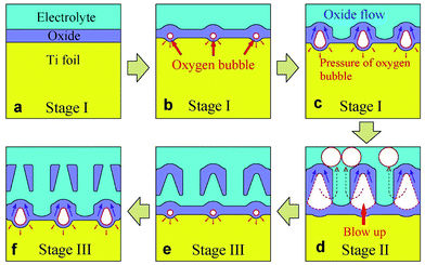 | ||
| Fig. 4 Schematic diagrams showing three growth stages of multilayer anodic TiO2 nanotubes formed in HBF4-containing electrolyte. | ||
Since the thickness of oxide layer no longer increases, ionic current density should decrease. However, total anodic current density is constant. Where is the reduced portion of ionic current density? Cao et al.44 and Anitha et al.45 considered the dissolution current density as the reduced part of ionic current density. However, Prakasam et al.46 indicated that chemical dissolution of oxide at the pore bottom does not contribute to the anodic current density. Thompson et al.47 also thought that the dissolution reaction of the oxide is chemical in nature and does not contribute to anodic current. In fact, electronic current arises from dielectric breakdown of oxide. Electronic current density (je) increases exponentially with the increase of oxide thickness (eqn (6)).18
| je = je0 × exp(θd) | (6) |
Electronic current gives rise to oxygen bubbles in oxide (eqn (7) and Fig. 4b).
| 2O2− = O2↑ + 4e− | (7) |
Because of the pressure from electrolyte and formed oxide, oxygen bubbles can not escape from barrier layer into electrolyte immediately after they are formed (Fig. 4b).
As the electronic current increases with the oxide thickness, oxygen bubbles grow bigger and bigger in barrier layer (Fig. 4c). Newly formed oxide would flow upwards around oxygen bubbles.19,40–43,45,48 The flow is suggested to be driven by the stresses caused by film growth and electric field.16 In other words, the stresses are attributed to the electrostriction and volume change associated with oxidation of titanium.16 Finally, the pressure in oxygen bubbles becomes bigger than the pressure of electrolyte and the formed oxide. Thus, oxygen bubbles start to escape (Fig. 4d).
It should be noted that the escape ways of oxygen bubbles in two electrolytes are different. In NH4F-containing electrolyte, oxygen bubbles penetrate barrier layer and move upwards in nanotubes (Fig. 5a). However, in HBF4-containing electrolyte, oxygen bubbles break TiO2 nanotube sidewalls and move upwards in gaps between nanotubes (Fig. 5b). Difference between the two escape ways of oxygen bubbles could be attributed to the difference between magnitudes of ionic current and electronic current in two electrolytes. It is well known that at the inflection point (Ui) in stage I (Fig. 3a and b), thickness of barrier layer would reach a critical value (dc).18 Thickness of barrier layer would roughly keep constant during later anodization. Total anodizing current densities in two electrolytes are the same. Resistances of barrier layer in two electrolytes are proportional to thickness of barrier layer (d). The increase of potential in stage I is ascribed to the growth of barrier layer thickness under galvanostatic condition. Therefore, dc is linearly proportional to the anodic potential at the inflection point (Ui). Ui in HBF4-containing electrolyte (126.56 V) is higher than that in NH4F-containing electrolyte (66.00 V). The value of dc in HBF4-containing electrolyte is nearly twice as big as that in NH4F-containing electrolyte. After the inflection point, electronic current density exponentially increases (eqn (6)).16,18,19 In HBF4-containing electrolyte, thicker barrier layer presses oxygen bubbles against Ti substrates and nanotube walls. The growing oxygen bubbles are flattened by this pressure. As a consequence, the pressure in oxygen bubbles leads to thinner nanotube walls (Fig. 4c). Thus, oxygen bubbles will blow up from nanotube walls in HBF4-containing electrolyte (Fig. 5b). Blowing up effect should account for the extremely thin nanotube walls at the bottom of nanotubes (Fig. 1b2 and c2). However, because barrier layer in NH4F-containing electrolyte is about half of that in HBF4-containing electrolyte, oxygen bubbles in NH4F-containing electrolyte would blow up from their upper oxide layer (Fig. 5a).
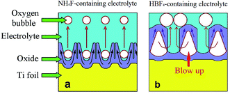 | ||
| Fig. 5 Schematic diagrams showing the escape ways of oxygen bubbles in (a) NH4F-containing electrolyte and (b) HBF4-containing electrolyte. | ||
We name the pressure in oxygen bubble when it escapes from oxide as escaping pressure. Because of the thicker barrier layer, escaping pressure in oxygen bubble in HBF4-containing electrolyte is higher than that in NH4F-containing electrolyte. Therefore, diameters of escaped oxygen bubbles in HBF4-containing electrolyte are bigger than in that NH4F-containing electrolyte. In HBF4-containing electrolyte, the inner diameters at the bottom of nanotubes in first and middle layer are close to the outer diameters (90 nm in Fig. 1b2, 72 nm in Fig. 1c2). However, the inner bottom diameter of TiO2 nanotubes formed in NH4F-containing electrolyte is 45 nm (inset of Fig. 2b). Yu et al.43 suggested that the inner bottom diameter of TiO2 nanotubes is close related to the diameter of escaped oxygen bubbles. Thus, the escaped oxygen bubbles in HBF4-containing electrolyte are bigger than those in NH4F-containing electrolyte. In the following anodization process, escape of bigger oxygen bubbles results in much larger potential oscillations in HBF4-containing electrolyte than that in NH4F-containing electrolyte.
After oxygen bubbles escape from barrier layer, electrolyte enters the pores left by oxygen bubbles, which leads to the decrease of potential (stage II, Fig. 4d). Taveira et al.25 suggested that an easy access of electrolyte was formed on the broken area of nanotubes, which led to the decrease of potential. When all of the TiO2 nanotube walls are broken by oxygen bubbles, anodizing potential is lowest, and anodization reaches stage III. New oxygen bubbles will be formed by electronic current during subsequent anodization (Fig. 4e).
In stage III, the anodic potential and thickness of barrier layer both kept roughly constant. Oxygen bubbles were formed continuously and then blow up in barrier layer. Oxide flows upwards around oxygen bubbles, and therefore nanotubes are formed. In HBF4-containing electrolyte, oxygen bubbles grow and broaden the bottom of anodic TiO2 nanotubes. Then oxygen bubbles blow up through the sidewalls of nanotubes (Fig. 4d and 5b). Accordingly, the A-shaped sidewall thickness profiles of TiO2 nanotubes are formed. And at the same time, the extremely thin sidewall at the nanotube bottoms would be damaged by the released oxygen bubbles, thus resulting in an individual layer of TiO2 nanotubes (Fig. 4e). In NH4F-containing electrolyte, oxygen bubbles move upwards in nanotubes. Due to the lower pressure of electrolyte on the top of nanotubes, oxygen bubbles expand the inner diameters at the top of nanotubes. Owing to the movement and expansion of oxygen bubbles, V-shaped TiO2 nanotubes are finally formed in NH4F-containing electrolyte (Fig. 5a). In HBF4-containing electrolyte, oxygen bubbles moved upwards in gaps between TiO2 nanotubes and separated neighbouring TiO2 nanotubes. Thus TiO2 nanotubes were spaced in top image in HBF4-containing electrolyte (Fig. 1b1). However, oxygen bubbles moved upwards inside TiO2 nanotubes, and as a result, TiO2 nanotubes were not spaced in top image in NH4F-containing electrolyte (Fig. 2a).
It should be noted that the oxide layer on the top of anodic TiO2 nanotubes will be dissolved by HBF4-containing electrolyte (Fig. 4f). Therefore, we obtained the final anodic TiO2 nanotubes with through holes on the top (Fig. 1b).
Due to the damage of nanotube walls by oxygen bubbles, the whole TiO2 nanotube layer is divided to nanotube multilayers (Fig. 4f). Nevertheless, oxygen bubbles do not blow up exactly at the same time because the surface of Ti substrate is of great unevenness. As a consequence, anodic potential–time curve was not regularly pulsating during anodizing in HBF4-containing electrolyte. The oxygen bubbles' blowing up effect is the reason for the division of TiO2 nanotube layer and the oscillation of anodizing potential.
In summary, electrochemical reactions of anodizations in HBF4-containing electrolyte and NH4F-containing electrolyte are similar. Different magnitudes of ionic current and electronic current in two electrolytes result in different volumes of escaped oxygen bubbles and different escape ways of oxygen bubbles, thus different architectures of TiO2 nanotubes are formed. Due to the damage of nanotube walls by oxygen bubbles, the TiO2 nanotube layer is divided to multilayers in HBF4-containing electrolyte.
Conclusions
When the anodization of titanium was performed in HBF4-containing electrolyte, multilayer anodic TiO2 nanotubes were obtained. Nanotubes in the middle layers show a unique A-shaped sidewall thickness profile. Formation mechanism of the multilayer anodic TiO2 nanotubes and A-shaped sidewall thickness profile could not be explained by traditional field-assisted dissolution mechanism. And then a possible formation mechanism of the multilayer anodic TiO2 nanotubes is proposed. Migration of ions forms ionic current and produces oxide. Oxygen bubbles, which arise from the electronic current, act as moulds during oxide growth. Oxide flows around oxygen bubbles and forms nanotubes. Unlike the formation of nanotubes in NH4F-containing electrolyte where oxygen bubbles escape from barrier layer and move upwards in nanotubes, in HBF4-containing electrolyte, oxygen bubbles break nanotube walls and move upwards in gaps between nanotubes. Therefore, the unique escape way of oxygen bubbles formed the A-shaped sidewall thickness profile and homogeneous nanotube multilayers in the HBF4-containing electrolyte.Acknowledgements
This work was financially supported by the National Natural Science Foundation of China (Grant No. 61171043, 51577093) and the Universities Natural Science Research Project (16KJB430032) and Qing Lan Project of Jiangsu Province.References
- H. Mokarami Ghartavol, M. Mohammadi, A. Afshar, F. C.-N. Hong and Y.-R. Jeng, RSC Adv., 2016, 6, 101737 RSC.
- J. M. Hernández-López, A. Conde, J. J. de Damborenea and M. A. Arenas, RSC Adv., 2014, 4, 62576 RSC.
- S. Chen, M. Liao, P. Yang, S. Yan, R. Jin and X. Zhu, RSC Adv., 2016, 6, 84309 RSC.
- L. X. Zheng, Y. C. Dong, H. D. Bian, C. Lee, J. Lu and Y. Y. Li, Electrochim. Acta, 2016, 203, 257 CrossRef CAS.
- D. Yu, X. Zhu, Z. Xu, X. Zhong, Q. Gui, Y. Song, S. Zhang, X. Chen and D. Li, ACS Appl. Mater. Interfaces, 2014, 6, 8001 CAS.
- V. Zwilling, M. Aucouturier and E. Darque-Ceretti, Electrochim. Acta, 1999, 45, 921 CrossRef CAS.
- J. M. Macak, K. Sirotna and P. Schmuki, Electrochim. Acta, 2005, 50, 3679 CrossRef CAS.
- J. M. Macák, H. Tsuchiya and P. Schmuki, Angew. Chem., Int. Ed., 2005, 44, 2100 CrossRef PubMed.
- L. V. Taveira, J. M. Macák, H. Tsuchiya, L. F. P. Dick and P. Schmuki, J. Electrochem. Soc., 2005, 152, B405 CrossRef CAS.
- D. Regonini, C. R. Bowen, A. Jaroenworaluck and R. Stevens, Mater. Sci. Eng., R, 2013, 74, 377 CrossRef.
- C. Richter, Z. Wu, E. Panaitescu, R. Willey and L. Menon, Adv. Mater., 2007, 19, 946 CrossRef CAS.
- N. F. Fahim, T. Sekino, M. F. Morks and T. Kusunose, J. Nanosci. Nanotechnol., 2009, 9, 1803 CrossRef CAS PubMed.
- C. Chang, X. Huang, Y. Liu, L. Bai, X. Yang, R. Hang, B. Tang and P. K. Chu, Electrochim. Acta, 2015, 173, 345 CrossRef CAS.
- F. Hu, X. Lin, S. L. Zhu, X. J. Yang and Z. D. Cui, Appl. Surf. Sci., 2012, 258, 3260 CrossRef CAS.
- Ö. Ö. Çapraz, P. Shrotriya, P. Skeldon, G. E. Thompson and K. R. Hebert, Electrochim. Acta, 2015, 167, 404 CrossRef.
- R. Yang, L. Jiang, X. Zhu, Y. Song, D. Yu and A. Han, RSC Adv., 2012, 2, 12474 RSC.
- Y. Zhang, D. Yu, M. Gao, D. Li, Y. Song, R. Jin, W. Ma and X. Zhu, Electrochim. Acta, 2015, 160, 33 CrossRef CAS.
- B. Chong, D. Yu, R. Jin, Y. Wang, D. Li, Y. Song, M. Gao and X. Zhu, Nanotechnology, 2015, 26, 145603 CrossRef PubMed.
- Y. Zhang, H. Fan, X. Ding, Q. Yan, L. Wang and W. Ma, Electrochim. Acta, 2015, 176, 1083 CrossRef CAS.
- J. Xing, H. Li, Z. Xia, J. Chen, Y. Zhang and L. Zhong, Electrochim. Acta, 2014, 134, 242 CrossRef CAS.
- K. Lee, A. Mazare and P. Schmuki, Chem. Rev., 2014, 114, 9385 CrossRef CAS PubMed.
- P. Roy, S. Berger and P. Schmuki, Angew. Chem., Int. Ed., 2011, 50, 2904 CrossRef CAS PubMed.
- A. Baron-Wiecheć, M. G. Burke, T. Hashimoto, H. Liu, P. Skeldon, G. E. Thompson, H. Habazaki, J. J. Ganem and I. C. Vickridge, Electrochim. Acta, 2013, 113, 302 CrossRef.
- J. M. Montero-Moreno, M. Sarret and C. Müller, Microporous Mesoporous Mater., 2010, 136, 68 CrossRef CAS.
- L. V. Taveira, J. M. Macak, K. Sirotna, L. F. P. Dick and P. Schmuki, J. Electrochem. Soc., 2006, 153, B137 CrossRef CAS.
- Y. Zhang, W. Cheng, F. Du, S. Zhang, W. Ma, D. Li, Y. Song and X. Zhu, Electrochim. Acta, 2015, 180, 147 CrossRef CAS.
- S. P. Albu, D. Kim and P. Schmuki, Angew. Chem., Int. Ed., 2008, 120, 1942 CrossRef.
- X. Zhou, N. T. Nguyen, S. Özkan and P. Schmuki, Electrochem. Commun., 2014, 46, 157 CrossRef CAS.
- V. C. Anitha, A. N. Banerjee, S. W. Joo and B. K. Min, Mater. Sci. Eng., B, 2015, 195, 1 CrossRef CAS.
- X. Wang, L. Sun, S. Zhang and D. Zhao, Electrochim. Acta, 2013, 107, 200 CrossRef CAS.
- D. Kowalski, D. Kim and P. Schmuki, Nano Today, 2013, 8, 235 CrossRef CAS.
- S. P. Albu, A. Ghicov, S. Aldabergenova, P. Drechsel, D. LeClere, G. E. Thompson, J. M. Macak and P. Schmuki, Adv. Mater., 2008, 20, 4135 CAS.
- K. Yasuda and P. Schmuki, Electrochim. Acta, 2007, 52, 4053 CrossRef CAS.
- Z. Su and W. Zhou, Adv. Mater., 2008, 20, 3663 CrossRef CAS.
- M. Paulose, H. E. Prakasam, O. K. Varghese, L. Peng, K. C. Popat, G. K. Mor, T. A. Desai and C. A. Grimes, J. Phys. Chem. C, 2007, 111, 14992 CAS.
- W. Krengvirat, S. Sreekantan, A. F. M. Noor, G. Kawamura, H. Muto and A. Matsuda, Electrochim. Acta, 2013, 89, 585 CrossRef CAS.
- J. M. Macak, H. Hildebrand, U. Marten-Jahns and P. Schmuki, J. Electroanal. Chem., 2008, 621, 254 CrossRef CAS.
- G. K. Mor, O. K. Varghese, M. Paulose, K. Shankar and C. A. Grimes, Sol. Energy Mater. Sol. Cells, 2006, 90, 2011 CrossRef CAS.
- L. Xiao and K. E. Johnson, J. Electrochem. Soc., 2003, 150, E307 CrossRef CAS.
- X. Zhu, Y. Song, D. Yu, C. Zhang and W. Yao, Electrochem. Commun., 2013, 29, 71 CrossRef CAS.
- Y. Li, Z. Y. Ling, X. Hu, Y. Liu and Y. Chang, RSC Adv., 2012, 2, 5164 RSC.
- X. M. Zhong, D. L. Yu, S. Y. Zhang, X. Chen, Y. Song, D. D. Li and X. F. Zhu, J. Electrochem. Soc., 2013, 160, E125 CrossRef CAS.
- D. Yu, S. Zhang, X. Zhu, H. Ma, H. Han and Y. Song, J. Solid State Electrochem., 2014, 18, 2609 CrossRef CAS.
- C. Cao, J. Li, X. Wang, X. Song and Z. Sun, J. Mater. Res., 2011, 26, 437 CrossRef CAS.
- V. Anitha, A. Banerjee, S. W. Joo and B. K. Min, Mater. Sci. Eng., B, 2015, 195, 1 CrossRef CAS.
- H. E. Prakasam, K. Shankar, M. Paulose, O. K. Varghese and C. A. Grimes, J. Phys. Chem. C, 2007, 111, 7235 CAS.
- J. Oh and C. V. Thompson, Electrochim. Acta, 2011, 56, 4044 CrossRef CAS.
- S. Y. Zhang, D. L. Yu, D. D. Li, Y. Song, J. F. Che, S. Y. You and X. F. Zhu, J. Electrochem. Soc., 2014, 161, E135 CrossRef CAS.
| This journal is © The Royal Society of Chemistry 2017 |

