 Open Access Article
Creative Commons Attribution 3.0 Unported Licence
A microcube-based hybrid piezocomposite as a flexible energy generator†
Yong Zhangab,
Wanlin Zhuc,
Chang Kyu Jeongb,
Huajun Suna,
Guang Yangb,
Wen Chen *a and
Qing Wang*b
aState Key Laboratory of Advanced Technology for Materials Synthesis and Processing, School of Materials Science and Engineering, Wuhan University of Technology, Wuhan 430070, P. R. China. E-mail: chenw@whut.edu.cn
bDepartment of Materials Science and Engineering, The Pennsylvania State University, University Park, Pennsylvania 16802, USA. E-mail: wang@matse.psu.edu
cSchool of Materials Science and Engineering, Shaanxi University of Science and Technology, Xi'an 710021, P. R. China
First published on 26th June 2017
Abstract
Harvesting energy from surrounding mechanical sources to power low-power portable electronics has attracted worldwide attention during the last decade. Herein, we present a high-performance piezoelectric energy generator (PEG) based on lead zirconate titanate (PbZr0.52Ti0.48O3, PZT) microcubes and poly(vinylidenefluoride-co-trifluoroethylene) (P(VDF-TrFE)). The PZT microcubes with tetragonal perovskite phase were prepared by one-step hydrothermal method. It is demonstrated that cube-shaped piezoelectric particles are advantageous over traditional spherical particles because external force can be readily concentrated on the edges of cubes to generate higher piezoelectric potential. Moreover, different from most of the previous flexible piezoelectric generators, the utilization of high elastic modulus, piezoelectric-active matrix P(VDF-TrFE) in our piezocomposites benefits power generations. The composite with a metal–insulator–metal (MIM) structure produces an open-circuit voltage up to ∼16 V under bending motions. A maximum instantaneous power density of ∼50 μW cm−3 has been obtained at a load resistance of 160 MΩ. This work provides a facile approach to enhanced piezoelectric response in flexible composites via tailoring the geometry of ceramic fillers.
1. Introduction
The demand for energy to power the increasing amount of portable electronics motivates researchers worldwide to develop various high-performance flexible energy harvesters.1–4 A variety of energy harvesting techniques to collect waste energy from the ambient environment have been extensively studied, such as solar cells for sunlight, thermoelectric devices for gradient heat, and piezoelectric and triboelectric materials for mechanical motion.5,6 Among them, mechanical sources (e.g. the vibrations of machines, human activities, automobile movement, acoustic waves, etc.;) are the most abundant and the most easily accessible at any time and everywhere.7–11It is thus highly desirable to develop piezoelectric materials and devices for transducing mechanical energy into electricity because of their direct conversion ability with mechanical robustness.4 Especially, perovskite materials such as ZnSnO3,12 BaTiO3,13 PbTiO3,3 KNaNbO3 14 have been introduced into polymer matrix to form piezoelectric composites to harvest mechanical energy from ambient environment. The composite structure combines the merits of high piezoelectric coupling coefficient of inorganic fillers and mechanical flexibility and scalability of polymer matrix.15 Most of the previous studies have focused on the dispersion of perovskite materials in polydimethylsiloxane (PDMS).16,17 However, PDMS elastomer is often too soft to efficiently transfer external mechanical stimulation to inorganic fillers and unable to induce high piezoelectric response of composites.
In this work, we describe the hybrid piezoelectric energy generator (PEG) using poly(vinylidenefluoride-co-trifluoroethylene) (P(VDF-TrFE)) as matrix.18 P(VDF-TrFE) has much higher Young's modulus (>0.8 GPa) than PDMS (>0.3 MPa), resulting in effectively transferring mechanical stress from matrix to piezoelectric fillers. In addition, it is known that the piezoelectric and dielectric responses are greatly affected by the shape of fillers because mechanical force is highly related to geometric aspects.9,19 PbZr0.52Ti0.48O3 (PZT) microcubes are thus utilized as piezoelectric fillers of the composites as they are thought to be stronger stress concentrators than sphere particles due to the presence of edges and corners of cube.20 The PZT microcube particles were successfully fabricated by one-step hydrothermal method. The flexible PEG based on PZT microcubes and P(VDF-TrFE) was fabricated by scalable and low-cost solution casting method.21 The PZT microcube/P(VDF-TrFE) PEG was generated a voltage up to ∼16 V on bending and releasing, which is higher than that of PZT/PDMS or PZT microsphere/P(VDF-TrFE) composites.16,22 The dependences of output signal on displacement, frequency and load resistances were characterized and analyzed. A peak instantaneous power density of up to ∼50 μW cm−3 indicates its promising for energy harvesting application.
2. Experimental
2.1 Synthesis of PZT microcubes
PZT microcubes were fabricated by one-step hydrothermal reaction. In a typical experiment, 0.4988 g of zirconium(IV) butoxide solution [Zr(OC4H9)4] (80 wt% in 1-butanol, Sigma-Aldrich) and 0.2813 g of titanium(IV) isopropoxide [Ti(C3H7O)4] (97%, Sigma-Aldrich) were added into 19.5 mL of isopropyl alcohol [(CH3)2CHOH] (99.7%, Sinopharm Chemical Reagent Co., Ltd) under vigorous stirring for half an hour. Then, a mixture of 4.2 mL of isopropyl alcohol and 0.56 mL of deionized water was added dropwise to initiate the hydrolytic process. The obtained suspension was subsequently centrifuged to collect the precipitate. The precipitate was washed with deionized water for five cycles in a centrifuge (5 min at 4000 rpm) and then transferred to a homemade 30 mL stainless autoclave with Teflon lining. 7.1 mL of tetramethylammonium hydroxide [(CH3)4N(OH)] (25 wt% aqueous solution, Sinopharm Chemical Reagent Co., Ltd) and 0.7625 g of lead(II) acetate trihydrate [Pb(CH3CO2)2·3H2O] (99.5%, Sinopharm Chemical Reagent Co., Ltd) were weighted and then introduced into the Teflon lining. Deionized water was finally added until 65% volume of the autoclave was occupied. After stirring for 10 min, the autoclave was heated to 150–250 °C and maintained for 12 h. After cooling down to room temperature, the obtained powders (PZT microcubes) were washed with deionized water till the neutral and then dried overnight at 70 °C under vacuum.2.2 Fabrication of piezoelectric composite generator
Piezoelectric P(VDF-TrFE) (70/30 mol%) was dissolved in N,N-dimethylformamide (DMF) by stirring for 24 h to form a homogeneous solution. The concentration of the solution was set at 80 mg mL−1. Then, PZT microcubes (0, 10, 15, 20 wt%) were added into the solution and stirred for another 24 h. Thereafter, the composite was casted on a glass substrate and baked at 60 °C overnight. The composite film was subsequently peeled off from the substrate and thermally processed at 135 °C under vacuum for 24 h. Finally, ∼200 nm gold layer was sputtered on both sides of the composite films for electrical measurement. The typical thickness of the composite films is around 100 μm. In order to achieve a high piezoelectric coupling coefficient, an appropriate poling procedure is needed. The poling procedure adopted in this work is divided into following four steps due to the piezoelectric discrepancy between PZT and P(VDF-TrFE): (i) the composite film was firstly heated to 120 °C and poled at ∼4 kV for 2 h; (ii) the poling electric field was maintained while gradually cooling the sample down to room temperature; (iii) the composite film was reheated to 50 °C and then a poling electric field of ∼1 kV was applied in an opposite direction for 0.5 h; (iv) the composite film was cooled down to room temperature with electric field kept on.2.3 Measurements and characterization
The crystal structures of PZT microcubes and pure P(VDF-TrFE) films were characterized by X-ray diffraction (PANalytical, X'Pert Pro MPD theta–theta Diffractometer, Holland) with Cu Kα radiation operating at 40 kV and 20 mA. A field-emission scanning electron microscope (FE-SEM, Hitachi S-4800, Japan) was used to characterize the surface and cross-sectional morphologies. Transmission electron microscopy (TEM, FEI Tecnai G2, USA) images were taken using an acceleration voltage of 200 kV. The electrical signal that generated from PEG under repeated bending and releasing was collected by use of a digital Oscilloscope (Wavesurfer 3022, Teledyne LeCroy, USA). A customized bending machine was used to control the frequency and displacement.3. Results and discussion
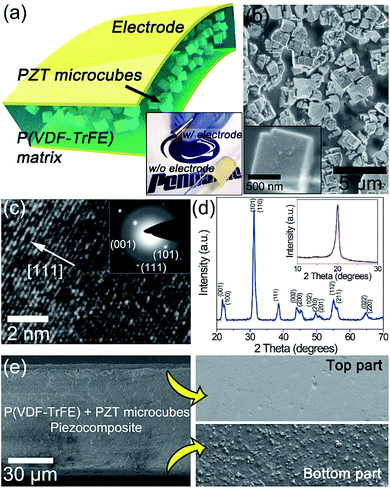
Fig. 1a shows the overall schematic of the PZT microcube/P(VDF-TrFE) piezocomposites. The one-step hydrothermally synthesized PZT microcube particles were dispersed in P(VDF-TrFE) solutions, and the mixtures were solidified on a glass substrate. The PZT near morphotropic phase boundary (MPB), which has been widely used in actuators and transducers,23 is designed herein as a high-performance piezoelectric material.24 The microcube-type piezoelectric particle is highly desirable for piezocomposite-based generators. This is because that the regular cube-type particle has clear geometric stress concentrators such as edges and corners, which are more readily subject to applied mechanical force than sphere particles. Micrometer-scale particles are selected to maintain the piezoelectricity of PZT. It is known that the ferroelectric phase (P4mm) of PZT is reduced in nanoscale particles, causing the relative increment of the paraelectric phase (Pm3m) on particle surfaces.25 P(VDF-TrFE) copolymer is advantageous as the matrix of piezoelectric composite due to not only its own piezoelectric activity but also high elastic modulus, leading to efficient transfer of mechanical stress to piezoelectric filler particles. Therefore, the PZT microcube particles and P(VDF-TrFE) matrix are chosen herein for composite-based piezoelectric applications. After being detached from the glass substrate, metal electrodes were deposited onto both sides of piezocomposite for a metal–insulator–metal (MIM) structure. The inset of Fig. 1a shows the actual flexible PZT microcube/P(VDF-TrFE) piezocomposite with and without MIM type electrodes, respectively. The casted P(VDF-TrFE) matrix has another merit that metal electrodes can be directly deposited on the surface without any delamination, in contrast to PDMS matrix. This aspect can exclude the triboelectric artifact induced by the separately attached electrode sheets.As presented in the scanning electron microscopy (SEM) images (Fig. 1b), the size of the PZT microcubes is around 1–2 μm with regular cubical edges and corners. Fig. 1c shows the high-resolution transmission electron microscopy (HRTEM) image of a single PZT microcube with a lattice spacing of 0.238 nm, which corresponds to the (111) lattice planes of tetragonal PZT. The (001), (101) and (111) diffracted planes of tetragonal PZT were clearly presented in the selected area electron diffraction (SAED) pattern, indicative of the single crystal nature of the microcube. Pure tetragonal perovskite phase of PZT microcubes has been obtained in the one-step hydrothermal process, and no obvious impurity phase has been detected in the X-ray diffraction (XRD) patterns (Fig. 1d). To evaluate the influence of hydrothermal reaction temperature on the crystal structures, the XRD patterns of the PZT prepared under various hydrothermal reaction temperatures are presented in Fig. S1, (ESI†). The inset of Fig. 1d is the XRD pattern of P(VDF-TrFE) film annealed at 135 °C for 24 h. The single peak at 20° clearly indicates that the copolymer presents the crystalline configuration with piezoelectric β phase without other paraelectric configurations.26 The chemical composition was also well maintained during the synthesis, as shown in the energy dispersive spectroscopy (EDS) mappings (Fig. S2, ESI†).
Fig. 1e is the cross-sectional SEM image of PZT microcube/P(VDF-TrFE) showing the thickness of the composite film is around 100 μm (the left image). There exists different distribution of PZT microcubes from top to bottom along the P(VDF-TrFE) matrix (the right images), indicating the presence of the off-centered mechanical neutral plane through the composite thickness.27 Note that off-centered mechanical neutral plane is highly important in flexible piezoelectric energy harvesters for applying net stress to the whole device by bending.15–17 If the particle distribution is same and device structure is symmetric from top to bottom, the mechanical neutral plane is centered and the net stress becomes zero despite bending deformation,28 resulting in no extracted piezoelectric signal. Therefore, the particle distribution difference in our device can guarantee the effective net stress and the piezoelectric response.
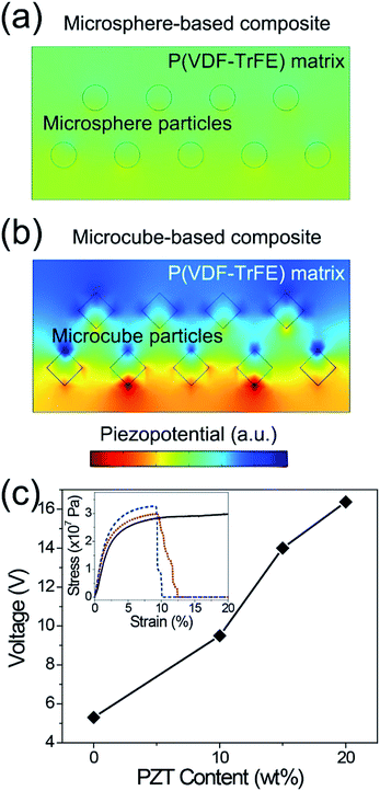
Using the finite element analyses (FEA), we simulated the piezopotential generated by PZT microsphere- and microcube-based composites to evaluate the effect of particle geometry on the piezoelectric performance of the composites, as described in Fig. 2a and b. When the same mechanical stress is applied, the microcube-based piezocomposite induces much higher piezoelectric potential throughout the thickness of composite than the corresponding microsphere-based piezocomposite. It is because the geometrically angular and sharp aspects of microcubes can collect large mechanical stress from external force, while the smooth surface of microspheres releases the mechanical stimulation into the matrix dispersively. In order to investigate the influence of PZT content in the matrix on the output response of flexible PEG, a series of PEGs have been fabricated by introducing different mass fraction (10, 15 and 20 wt%) of PZT microcube particles into P(VDF-TrFE) matrix. As expected by theoretical simulation, the output voltage generated by bending motion was increased steadily with increasing PZT concentration, as shown in Fig. 2c. However, the PZT microcubes could not be mixed above the fraction of 20 wt% because it became too viscous to be well casted.
To indicate the advantages of P(VDF-TrFE) as the matrix, we also evaluated the stress–strain curves of P(VDF-TrFE) films with various PZT fractions (the inset of Fig. 2c). Even in the pristine P(VDF-TrFE) film, the Young's modulus is about 800 MPa which is ∼1000 times higher than that of PDMS elastomer.29 After mixing with 20 wt% of PZT microcubes, the elastic modulus of the composite increases over 1 GPa. This result indicates that P(VDF-TrFE) is highly suitable for matrix in piezocomposite owing to not only its piezoelectric properties but also the excellent ability to stress-transferring medium. The voltage generated by the PEG can be calculated as:
 | (1) |
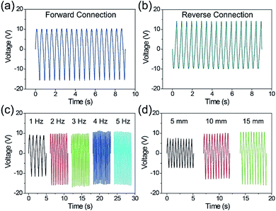
Fig. 3a shows the generated voltage signals from the flexible PZT microcube/P(VDF-TrFE) composite PEG upon repeated bending and releasing. Apparently, signals appear successively and persistently. To confirm that the detected electrical signal is indeed from the piezoelectric effect of the PEG device, a switching polarity test was successfully conducted, as presented in Fig. 3b.15–17 Note that the semi-asymmetry of voltage peaks (Fig. 3a and b) is due to the distribution difference of PZT microcube particles along the composite thickness. The PEG device with an effective area of 1.8 cm × 0.6 cm produces an open-circuit output voltage of ∼16 V when the bending frequency is 2 Hz. This output is higher than those of not only PZT spherical particles/PVDF composites but also even PZT particles/carbon nanotubes-reinforced PDMS composites.16,22 Therefore, the results further prove that the material selection takes a critical role in the piezocomposite-type generators.
The principle of flexible energy harvester is well known.15–17 The unidirectional pre-orientation of electric dipoles in PEG is obtained by the proper poling processes to overcome the discrepancy of piezoelectric coefficients between PZT fillers and P(VDF-TrFE) matrix.32 The PEG maintains electrical equilibrium state without any external force, thus there is no potential fluctuation in external load. On bending, the deviation of built-in potential is generated within the piezoelectric composite, followed by the potential difference throughout the external load to screen the electrical non-equilibrium of stressed PEG. When PEG recovers to the original shape, the potential difference in the opposite direction occurs in the same manner. This process of potential generation of PEG is illustrated in Fig. S3 (ESI†).
In many cases, the piezoelectric generators to scavenge mechanical energy (e.g. ocean waves, human activities, mechanical vibration, acoustic wave, etc.) from ambient environment need to be operated under the relatively low frequency range (<5 Hz).11 In this work, the output voltage values under different deformation frequencies (1–5 Hz) were measured, as shown in Fig. 3c. The output voltage increases steadily from ∼12 V at 1 Hz to ∼16 V at 2 Hz, and then saturates after 3 Hz. The relatively smaller output voltage under 1 Hz is presumably due to the slow charge extraction toward the measurement equipment.33 This finding is different from the previous result based on the PZT microparticles and CNTs as a charge extraction component in the composite, which exhibits the almost constant voltage signals with variation of frequency.16 The mechanical motions in ambient environment are usually irregular,34 which means that the PEG should be effective toward different degrees of deformation. Fig. 3d presents the relationship between various deformation displacements (from 5 to 15 mm) and output voltage. As expected, the output voltage value increases with increasing displacement because the increasing bending displacement induces the higher applied stress to piezoelectric composites, resulting in larger output voltage signals. These output characteristics of our flexible PEG show that it can be operated in ambient surroundings.
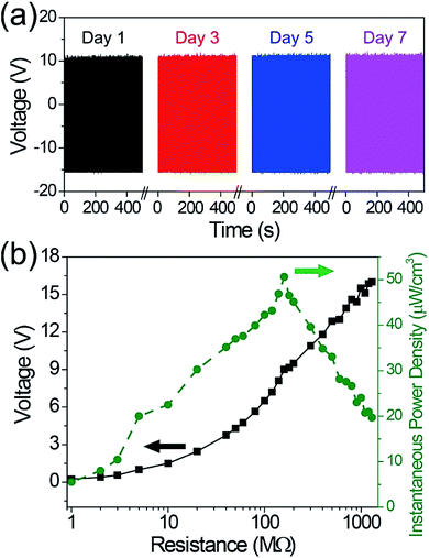
Moreover, the mechanical durability test was conducted to verify the stability of the PZT microcube/P(VDF-TrFE) composite PEG, as presented in Fig. 4a. The bending test was carried out at 5 Hz after aging for 1, 3, 5 and 7 days, respectively. There is rarely degradation of signal amplitude even after thousands of cycles, which guarantees the steady output performance of our flexible hybrid PEG. Fig. 4b is the plots of voltage and instantaneous power density as a function of load resistances ranging from 1 MΩ to 1.3 GΩ. The voltage increases steadily with increasing load resistances, and reaches a peak value of ∼16 V around 1 GΩ similar to open-circuit. The maximum instantaneous power density of ∼50 μW cm−3 was obtained at a resistance of 160 MΩ.
4. Conclusions
In summary, we have developed the flexible composite-type PEG using PZT microcube/P(VDF-TrFE) as optimized materials for the scalable and low-cost technology of composite-based piezoelectric energy harvesting. The piezoelectric PZT microcube particles were synthesized by the facile one-step hydrothermal process, and properly blended with P(VDF-TrFE) piezoelectric polymer matrix. The maximum output voltage and the instantaneous power density reach up to ∼16 V and ∼50 μW cm−3 under bending stimulation, respectively, which are greater than those of PZT spherical particles/PVDF and PZT/CNT-enhanced PDMS composites.27,31 The selection of the microcube has been theoretically verified by the FEA simulations. The flexible PZT microcube/P(VDF-TrFE) PEGs exhibit typical voltage harvesting characteristics and remarkable mechanical durability. Our result clearly shows that microcube-type particles and P(VDF-TrFE) are highly desirable for flexible composite-type energy harvesters due to their geometric and elastic properties as well as excellent piezoelectric activity. This work indicates the promise of the polymer composite utilizing the fillers with rationally designed morphology to high piezoelectric performance for energy harvesting.13,35–37Acknowledgements
The authors would like to thank the National Nature Science Foundation of China (No. 51372181, 51672198) for the financial support. Y. Z. acknowledges the fellowship provided by the China Scholarship Council (CSC).Notes and references
- Z. L. Wang and W. Wu, Angew. Chem., Int. Ed., 2012, 51, 11700–11721 CrossRef CAS PubMed.
- H. Van Ngoc and D. J. Kang, Nanoscale, 2016, 8, 5059–5066 RSC.
- Y. B. Lee, J. K. Han, S. Noothongkaew, S. K. Kim, W. Song, S. Myung, S. S. Lee, J. Lim, S. D. Bu and K.-S. An, Adv. Mater., 2017, 29, 1604500 CrossRef PubMed.
- J. Wu, H. Shi, T. Zhao, Y. Yu and S. Dong, Adv. Funct. Mater., 2016, 26, 7186–7194 CrossRef CAS.
- R. Ding, H. Liu, X. Zhang, J. Xiao, R. Kishor, H. Sun, B. Zhu, G. Chen, F. Gao, X. Feng, J. Chen, X. Chen, X. Sun and Y. Zheng, Adv. Funct. Mater., 2016, 26, 7708–7716 CrossRef CAS.
- E. M. A. Fuentes-Fernandez, B. E. Gnade, M. A. Quevedo-Lopez, P. Shah and H. N. Alshareef, J. Mater. Chem. A, 2015, 3, 9837–9842 CAS.
- C. Baek, J. H. Yun, J. E. Wang, C. K. Jeong, K. J. Lee, K.-I. Park and D. K. Kim, Nanoscale, 2016, 8, 17632–17638 RSC.
- S. H. Lee, C. K. Jeong, G.-T. Hwang and K. J. Lee, Nano Energy, 2015, 14, 111–125 CrossRef CAS.
- C. K. Jeong, I. Kim, K. Il Park, M. H. Oh, H. Paik, G. T. Hwang, K. No, Y. S. Nam and K. J. Lee, ACS Nano, 2013, 7, 11016–11025 CrossRef CAS PubMed.
- C. K. Jeong, J. H. Han, H. Palneedi, H. Park, G.-T. Hwang, B. Joung, S.-G. Kim, H. J. Shin, I.-S. Kang, J. Ryu and K. J. Lee, APL Mater., 2017, 5, 74102 CrossRef.
- Y. Hou, Y. Zhou, L. Yang, Q. Li, Y. Zhang, L. Zhu, M. A. Hickner, Q. M. Zhang and Q. Wang, Adv. Energy Mater., 2017, 7, 1601983 CrossRef.
- R. Guo, Y. Guo, H. Duan, H. Li and H. Liu, ACS Appl. Mater. Interfaces, 2017, 9, 8271–8279 CAS.
- K.-I. Park, S. Bin Bae, S. H. Yang, H. I. Lee, K. Lee and S. J. Lee, Nanoscale, 2014, 6, 8962–8968 RSC.
- M. K. Gupta, S.-W. Kim and B. Kumar, ACS Appl. Mater. Interfaces, 2016, 8, 1766–1773 CAS.
- K. Il Park, M. Lee, Y. Liu, S. Moon, G. T. Hwang, G. Zhu, J. E. Kim, S. O. Kim, D. K. Kim, Z. L. Wang and K. J. Lee, Adv. Mater., 2012, 24, 2999–3004 CrossRef PubMed.
- K.-I. Park, C. K. Jeong, J. Ryu, G.-T. Hwang and K. J. Lee, Adv. Energy Mater., 2013, 3, 1539–1544 CrossRef CAS.
- C. K. Jeong, K.-I. Park, J. Ryu, G.-T. Hwang and K. J. Lee, Adv. Funct. Mater., 2014, 24, 2620–2629 CrossRef CAS.
- Q. Li and Q. Wang, Macromol. Chem. Phys., 2016, 217, 1228–1244 CrossRef CAS.
- G. Zhang, X. Zhang, T. Yang, Q. Li, L.-Q. Chen, S. Jiang and Q. Wang, ACS Nano, 2015, 9, 7164–7174 CrossRef CAS PubMed.
- Y. R. Lin, C. Andrews and H. A. Sodano, J. Appl. Phys., 2010, 108, 64108 CrossRef.
- K. Han, Q. Li, C. Chanthad, M. R. Gadinski, G. Zhang and Q. Wang, Adv. Funct. Mater., 2015, 25, 3505–3513 CrossRef CAS.
- Y. Zhang, Y. Zhang, X. Xue, C. Cui, B. He, Y. Nie, P. Deng and Z. Lin Wang, Nanotechnology, 2014, 25, 105401 CrossRef PubMed.
- Z. Zhou, H. Tang and H. A. Sodano, Adv. Mater., 2014, 26, 7547–7554 CrossRef CAS PubMed.
- C. K. Jeong, S. B. Cho, J. H. Han, D. Y. Park, S. Yang, K.-I. Park, J. Ryu, H. Sohn, Y.-C. Chung and K. J. Lee, Nano Res., 2017, 10, 437–455 CrossRef CAS.
- H. W. Lee, S. Moon, C. H. Choi and D. K. Kim, J. Am. Ceram. Soc., 2012, 95, 2429–2434 CrossRef CAS.
- S. H. Bae, O. Kahya, B. K. Sharma, J. Kwon, H. J. Cho, B. Özyilmaz and J. H. Ahn, ACS Nano, 2013, 7, 3130–3138 CrossRef CAS PubMed.
- C. K. Jeong, K.-I. Park, J. H. Son, G.-T. Hwang, S. H. Lee, D. Y. Park, H. E. Lee, H. K. Lee, M. Byun and K. J. Lee, Energy Environ. Sci., 2014, 7, 4035–4043 CAS.
- M. Koo, K. Il Park, S. H. Lee, M. Suh, D. Y. Jeon, J. W. Choi, K. Kang and K. J. Lee, Nano Lett., 2012, 12, 4810–4816 CrossRef CAS PubMed.
- Z. Wang, A. A. Volinsky and N. D. Gallant, J. Appl. Polym. Sci., 2014, 131, 41050 CrossRef.
- S. Xu, Y. W. Yeh, G. Poirier, M. C. McAlpine, R. A. Register and N. Yao, Nano Lett., 2013, 13, 2393–2398 CrossRef CAS PubMed.
- M. Zhang, T. Gao, J. Wang, J. Liao, Y. Qiu, H. Xue, Z. Shi, Z. Xiong and L. Chen, Nano Energy, 2015, 11, 510–517 CrossRef CAS.
- H. L. W. Chan, P. K. L. Ng and C. L. Choy, Appl. Phys. Lett., 1999, 74, 3029 CrossRef CAS.
- L. Gu, N. Cui, L. Cheng, Q. Xu, S. Bai, M. Yuan, W. Wu, J. Liu, Y. Zhao, F. Ma, Y. Qin and Z. L. Wang, Nano Lett., 2013, 13, 91–94 CrossRef CAS PubMed.
- C. R. Saha, T. O'Donnell, N. Wang and P. McCloskey, Sens. Actuators, A, 2008, 147, 248–253 CrossRef CAS.
- C. K. Jeong, H. M. Jin, J. H. Ahn, T. J. Park, H. G. Yoo, M. Koo, Y. K. Choi, S. O. Kim and K. J. Lee, Small, 2014, 10, 337–343 CrossRef CAS PubMed.
- H. G. Yoo, M. Byun, C. K. Jeong and K. J. Lee, Adv. Mater., 2015, 27, 3982–3998 CrossRef CAS PubMed.
- G.-T. Hwang, V. Annapureddy, J. H. Han, D. J. Joe, C. Baek, D. Y. Park, D. H. Kim, J. H. Park, C. K. Jeong, K.-I. Park, J.-J. Choi, D. K. Kim, J. Ryu and K. J. Lee, Adv. Energy Mater., 2016, 6, 1600237 CrossRef.
Footnote |
| † Electronic supplementary information (ESI) available: XRD data, working mechanism illustration. See DOI: 10.1039/c7ra05605b |
| This journal is © The Royal Society of Chemistry 2017 |


