
 Open Access Article
 This Open Access Article is licensed under a Creative Commons Attribution-Non Commercial 3.0 Unported Licence
Nitrogen-doped porous carbon materials generated via conjugated microporous polymer precursors for CO2 capture and energy storage†
Yongjie Xua,
Shaoping Wua,
Shijie Ren *ab,
Junyi Jic,
Yong Yuea and
Jiajia Shena
*ab,
Junyi Jic,
Yong Yuea and
Jiajia Shena
aCollege of Polymer Science and Engineering, State Key Laboratory of Polymer Materials Engineering, Sichuan University, Chengdu, 610065, P. R. China. E-mail: rensj@scu.edu.cn
bKey Laboratory of Synthetic and Self-Assembly Chemistry for Organic Functional Molecules, Chinese Academy of Sciences, Shanghai, 200032, P. R. China
cCollege of Chemical Engineering, Sichuan University, Chengdu, 610065, P. R. China
First published on 26th June 2017
Abstract
Heteroatom doping and well-tuned porosity are regarded as two important factors of porous carbon materials (PCMs) for various applications. However, it is still difficult to tune a single variable while retaining the other factors unchanged, which restricts rational and systematic research on PCMs. In this work, in situ nitrogen-doped porous carbon material (NPCM-1) and its non-doped analogue PCM-1 were prepared by direct pyrolysis of conjugated microporous polymer precursors (TCMP-1 and CMP-1 respectively) with the same skeleton structure. It was found that the CO2 adsorption capability of the PCMs was significantly enhanced compared with their CMP precursors thanks to the optimized pore configuration. Meanwhile, NPCM-1 exhibits much better performance in supercapacitive energy storage than PCM-1 even though these two PCMs possess comparable porosity properties, which is probably due to the much improved electrical conductivity and wettability with the electrolytes because of the introduction of nitrogen doping. Thus, this work provides a valuable insight into the design and preparation of high performance PCMs for CO2 capture and energy storage applications.
Introduction
Porous carbon materials (PCMs) have been extensively studied in a range of energy and environment related applications due to the abundance of raw materials, thermal and chemical stability and structural diversity.1–3 Traditionally, PCMs are prepared by physical or chemical activation of biomass feedstocks, e.g. wood, coconut shells and rice husk.4,5 Recently, newly developed carbon materials such as carbon nanotubes6 and graphene7 have also been used as precursors to prepare PCMs by activation. Heteroatom doping has been found to be a rational method to improve the application properties of PCMs through the enhancement of interactions between PCMs and the adsorbates.8,9 However, PCMs prepared by traditional activation methods often suffer from broad pore size distribution10 and the inconvenience to introduce precisely located heteroatoms onto the skeletons of PCMs,11 which restricts their efficient applications in both gas adsorption and energy storage.12The rapid development of microporous organic polymers (MOPs) which possess intrinsic microporosity and tunable chemical structures has provided another option for the construction of PCMs.13 A variety of MOPs including porous aromatic frameworks (PAFs),14 conjugated microporous polymers (CMPs),15 covalent triazine-based frameworks (CTFs)16 and hypercrosslinked polymers (HCPs)17 have been used as pyrolysis precursors for the preparation of PCMs with precisely controlled chemical and porous structures for various applications. Among them, CMPs are particularly interesting thanks to their unique properties derived from the combination of extended conjugation with permanent microporosity.18 Through direct carbonization, the electrical conductivity of CMPs could be greatly enhanced and their pore structures could be further tuned as well.19 Also, CMPs synthesized from heteroatom containing monomers can be used as carbonization precursors to prepare heteroatom doped PCMs,20 in which the concentration, location and configuration of the heteroatoms can be fine-tuned by judicious selection of monomers.18 Although there have been a few reports related to the CMP-derived PCMs,21,22 the effects of porosity and heteroatom doping on their applications in CO2 capture and energy storage have not been systematically studied.
In this context, we prepared two porous carbon materials, PCM-1 and nitrogen-doped NPCM-1, by the carbonization of CMP precursors with the same skeleton structure and different chemical compositions. Separate influence of either porosity or nitrogen doping on the CO2 capture and energy storage performances of the PCMs are studied in detail. It is found that carbonization is an efficient method to optimize porosity of the CMP materials, which is highly advantageous for the improvement of CO2 adsorption capability, and the supercapacitive energy storage performance of the PCMs could be greatly enhanced by the in situ nitrogen doping strategy.
Experimental
Synthesis of CMP-1
To a flame-dried 3-necked flask under Ar atmosphere were added 1,3,5-triethynylbenzene (150 mg, 1 mmol), 1,3,5-tribromobenzene (315 mg, 1 mmol), tetrakis(triphenylphosphine)palladium (58 mg, 0.05 mmol) and copper(I) iodide (19 mg, 0.1 mmol). The mixture was evacuated and purged with Ar three times before DMF (30 mL) and triethylamine (10 mL) were added into the flask. The dark brown mixture was heated to 150 °C and stirred for 72 h under Ar. The mixture was cooled to room temperature and the insoluble precipitation was filtered and washed with distilled water, ethanol, acetone, CHCl3 and methanol. The product was further purified by Soxhlet extraction with methanol, THF and CHCl3 for 24 h each. The product was then dried in a vacuum oven at 100 °C overnight to yield light yellow powder (yield: 204.2 mg, 92%).Synthesis of TCMP-1
The preparation of TCMP-1 was similar to that of CMP-1 but 2,4,6-trichloro-1,3,5-triazine (M3) was used instead of 1,3,5-tribromobenzene (M2). TCMP-1 was obtained as brown powder (yield: 195.8 mg, 87%).Preparation of PCM-1
CMP-1 in a ceramic boat was put into a tube furnace, vacuated and purged with N2 three times at room temperature and then heated to 700 °C with a heating rate of 5 °C min−1. The sample was kept in the furnace for additional 2 h before cooled down to room temperature to give PCM-1 as a black powder.Preparation of NPCM-1
The preparation of N-PCM-1 was similar to that of PCM-1 but TCMP-1 was used as the precursor.Preparation of electrodes
The mass of the electrodes was prepared by grinding active materials (35 mg, 70 wt%), conductive additive (acetylene black: 10 mg, 20 wt%), and binder (polyvinylidene fluoride in N-methylpyrrolidinone solvent: 5 mg, 10 wt%) in a mortar. The Ni foam current collector was cast with the slurry, dried under vacuum at 120 °C for 5 h and then cut to a circular shape working electrodes with the diameter of 12 mm.Gas sorption analysis
Surface areas and pore size distributions of the samples were measured by N2 adsorption and desorption at 77 K using a BELSORB Max (BEL Japan Inc.). Samples were degassed at 120 °C for 12 h under vacuum before analysis. The surface areas were calculated using the BET model in the pressure range P/P0 from 0.05–0.1. The total pore volume was determined at a relative pressure of 0.99. Pore size distributions were derived from the isotherms using the nonlocal density functional theory (NL-DFT) pore model for carbon with cylindrical and slit pore model. CO2 isotherms were measured at 273 K on a BELSORB Max (BEL Japan Inc.).Electrochemical measurements
All electrochemical performances were measured by using coin-type cells of 2032 size and 6 M potassium hydroxide (KOH) as the electrolyte. The electrochemical performances were conducted by cyclic voltammograms (CV), galvanostatic charge/discharge experiments (GCD), electrochemical impedance spectroscopy (EIS), using a CHI660E electrochemical workstation. The cyclic voltammograms (CV) were obtained over the potential range of −1 to 0 V at a scanning rates from 5 to 500 mV s−1. Galvanostatic charge/discharge experiments (GCD) with current rates from 0.1 to 10 A g−1 in the voltage range of −1 to 0 V. Electrochemical impedance spectroscopy (EIS) measurements of the electrodes were recorded by applying a sine wave with an amplitude of 5.0 mV over the frequency range from 100 kHz to 10 mHz. Cycling performances of cells were measured by LAND CT2001A battery test system.The specific capacitance Cs (F g−1) of electrode materials was calculated by the discharge curve according to Cs = 4 × Ccell = 4 × IΔt/mΔV. The specific energy density E (W h kg−1) and specific power density P (W kg−1) were calculated by the following equations, respectively: E = 0.5 × Ccell × (ΔV)2/3.6, P = E/(Δt/3600), where Ccell (F g−1) is the experimentally determined specific capacitance, I (A) is the discharge current, and Δt (s), m (mg), and ΔV (V) are the total discharge time, the mass of active materials on the two electrodes, and the potential drop during discharge, respectively.
Results and discussion
As shown in Scheme 1, porous carbon material PCM-1 and its nitrogen doped counterpart NPCM-1 were prepared by the pyrolysis of two conjugated microporous polymer precursors possessing the same skeleton structure and different chemical compositions. The CMP precursors CMP-1 and TCMP-1 were both synthesized through A3 + B3 Sonogashira–Hagihara cross-coupling polymerization under the same reaction conditions. Different from CMP-1 which possesses a 1,3,5-benzene knot, nitrogen-rich TCMP-1 was constructed by alkyne-type monomer M1 and a 1,3,5-triazine containing monomer M3. Then, CMP-1 and TCMP-1 were carbonized at 700 °C for 2 h under N2 atmosphere, and the resulting porous carbon materials were labeled as PCM-1 and NPCM-1 respectively. The PCMs were obtained as black powders and insoluble in all solvents tested including THF, toluene, DMF, and chloroform, and were also found to be chemically stable in various aqueous conditions. | ||
| Scheme 1 The preparation route of PCM-1 and NPCM-1. | ||
Infrared spectra for the samples are shown in Fig. S1 (see ESI†). For the CMP precursors, the peaks at around 2200 cm−1, which are characteristic of bis-substituted acetylenes, are easily detected, indicating successful cross-coupling reactions during the polymerization. The characteristic terminal C–C triple bond stretching vibration peak at about 3300 cm−1 of TCMP-1 exhibits a much lower intensity than that of CMP-1, suggesting a higher degree of polymerization of the triazine-based polymer.23 After heat treatment, the infrared absorption peaks of PCM-1 and NPCM-1 flatten out, suggesting the carbonization of CMP precursors during the pyrolysis process.16 Raman spectroscopy was used to further confirm the structures of the as-prepared PCMs (Fig. S2†). The Raman spectrum of PCM-1 presents two typical peaks, the D band at 1320 cm−1 attributed to structural defects and the G band at around 1590 cm−1 associated with highly ordered graphite carbon.24 The D band and G band of NPCM-1 shift slightly to 1329 and 1583 cm−1, and the ID/IG ratio of NPCM-1 increases from 0.83 of PCM-1 to 1.08, indicating that the introduction of nitrogen element could increase the degree of defect in the porous carbon structure.25
The X-ray photoelectron spectroscopy (XPS) spectra of the samples are presented in Fig. 1a. The O 1s peak located at 532 eV could be mostly assigned to the absorbed atmospheric H2O and O2 molecules.26 The N 1s peak can only be observed in TCMP-1 and NPCM-1, verifying the existence of nitrogen atoms in these two samples (5.5 at% for TCMP-1 and 1.5 at% for NPCM-1). Compared with TCMP-1, the nitrogen content of NPCM-1 decreases dramatically after carbonization, and the decrease of the C–N bond in C 1s spectra also corroborates the drop of N content (Fig. S3†). Further analysis of the N 1s spectrum of the two samples shows that the nitrogen configurations are different for TCMP-1 and NPCM-1 (Fig. 1b and c). The single nitrogen peak in TCMP-1 splits to three peaks in NPCM-1, including the pyridinic N (398.8 eV), graphitic N (401.2 eV) and a small oxidized N (405.6 eV).16 These results show that the nitrogen concentration and configurations can be changed during the pyrolysis process. The emerging of graphitic N and pyridinic N in NPCM-1 can be attributed to the structure reconstruction and electron redistribution during carbonization and is potentially beneficial for supercapacitive energy storage.27
 | ||
| Fig. 1 XPS full spectrum survey of the samples (a), N 1s binding energy profiles of TCMP-1 (b) and NPCM-1 (c). | ||
Surface morphology and crystallinity of the CMP and PCM samples were investigated by scanning electron microscopy (SEM) and X-ray diffraction (XRD) respectively. As shown in the SEM images (Fig. 2, S4 and S5†), a three-dimensional network with interconnected pores can be found in CMP-1 and PCM-1 (Fig. 2a and b), while a bulk structure with a relatively smooth surface can be observed in TCMP-1 and NPCM-1 (Fig. 2c and d). Powder XRD patterns of all the samples show a broad peak at approximately 22.5° (Fig. S6†), indicating amorphous structures of both the CMPs and PCMs.7 These results suggest that the macroscopic structure and morphology of the CMPs are mostly maintained after the pyrolysis process.
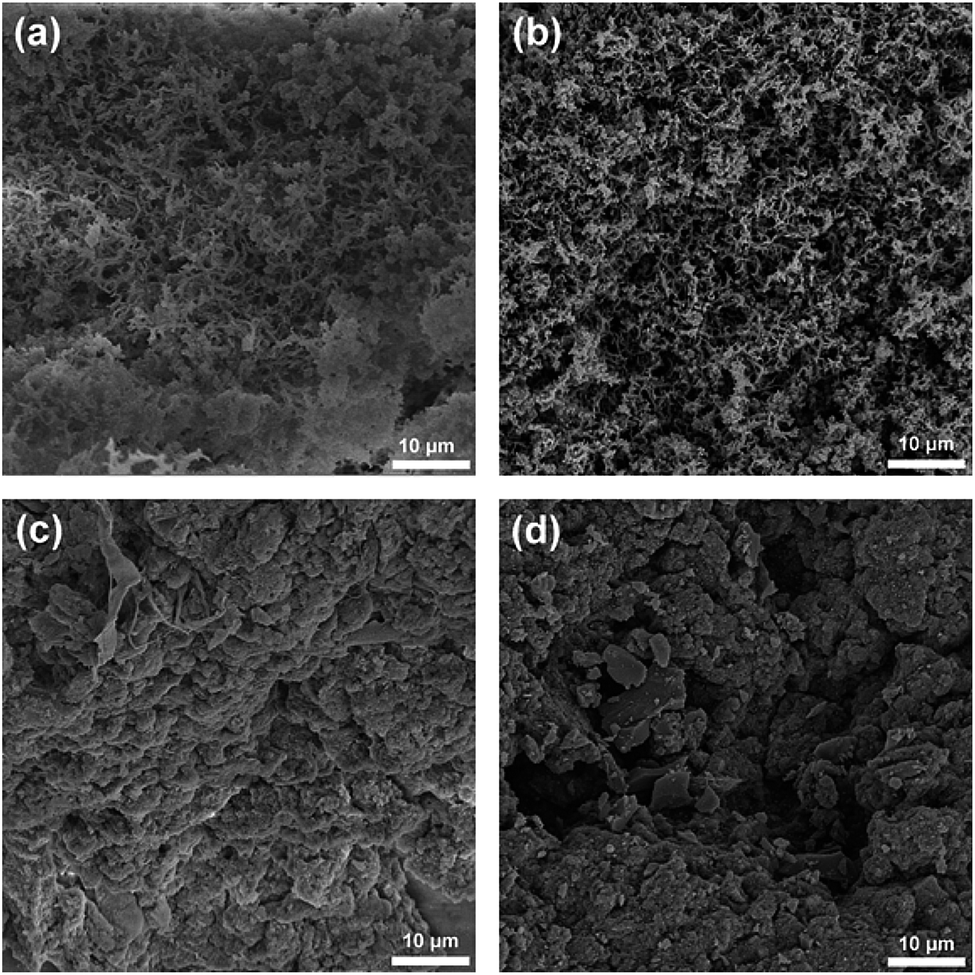 | ||
| Fig. 2 SEM images of CMPs and PCMs: (a) CMP-1, (b) PCM-1, (c) TCMP-1 and (d) NPCM-1. | ||
The surface area and pore structure of the samples were evaluated by nitrogen adsorption/desorption measurements at 77 K. The isotherms are shown in Fig. 3a and the porosity data are listed in Table 1. The four samples show comparable apparent BET surface areas ranging from 610 m2 g−1 (TCMP-1) to 718 m2 g−1 (NPCM-1). All samples give rise to a combination of type I and type IV adsorption isotherms according to the IUPAC classifications,28 indicating the existence of both micropores and mesopores in the networks.29 It is interesting to note that the shapes of the adsorption isotherms of PCM-1 and NPCM-1 remain almost unchanged compared with their carbonization precursors, CMP-1 and TCMP-1 respectively, although the adsorption quantity does display some slight variations. The fact that porosity of the carbonized materials corresponds well with their CMP precursors presents a significant advantage that it is possible to prepare PCMs with fine-tuned porosity by the selection of proper CMP precursors, whose porosity can be precisely controlled by rational selection of synthetic monomers.30
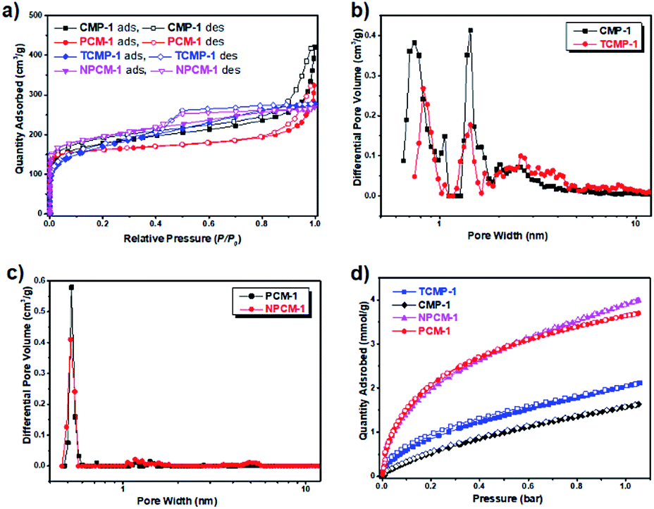 | ||
| Fig. 3 (a) N2 adsorption and desorption isotherms of the samples measured at 77 K (the adsorption and desorption branches are labelled with filled and empty symbols respectively). (b) Pore size distribution curves of CMP-1 and TCMP-1. (c) Pore size distribution curves of PCM-1 and NPCM-1. (d) CO2 adsorption isotherm profiles of CMP-1, PCM-1, TCMP-1 and NPCM-1 measured at 273 K (the adsorption and desorption branches are labelled with filled and empty symbols respectively). | ||
| Sample | SABETa (m2 g−1) | V0.1b | Vtot c | V0.1/Vtot | Pore size distribution (nm) | CO2 uptaked (mmol g−1) |
|---|---|---|---|---|---|---|
| a BET surface area calculated over the pressure range 0.05–0.1 P/P0.b V0.1 = pore volume at P/P0 = 0.1.c Vtot, total pore volume calculated at P/P0 = 0.99.d CO2 uptake measured at 1 bar at 273 K. | ||||||
| CMP-1 | 646 | 0.26 | 0.65 | 0.40 | 0.8, 1.4, 2–5 | 1.6 |
| TCMP-1 | 610 | 0.24 | 0.43 | 0.56 | 0.8, 1.4, 2–5 | 2.0 |
| PCM-1 | 630 | 0.24 | 0.50 | 0.48 | 0.5 | 3.6 |
| NPCM-1 | 718 | 0.29 | 0.42 | 0.69 | 0.5 | 3.9 |
Pore size distribution curves of the four samples are shown in Fig. 3b and c, as calculated using nonlocal density functional theory (NL-DFT). Compared with the CMP precursors CMP-1 and TCMP-1, which possess two micropore diameters centering around 0.8 nm and 1.4 nm and a proportion of mesopores around 2.0 to 5.0 nm, both of the carbonized materials PCM-1 and NPCM-1 exhibit a predominant micropore with a smaller pore size centering around 0.5 nm and much fewer mesopores. The level of microporosity in the materials is assessed by the ratio of micropore volume to the total pore volume (V0.1/Vtot). Accordingly, the carbonized PCMs show higher V0.1/Vtot values (0.48 of PCM-1 and 0.69 of NPCM-1) than their CMP precursors (0.40 of CMP-1 and 0.56 of TCMP-1). The main conclusion of the porosity analysis is that PCMs with comparable porosity properties can be prepared by the carbonization of CMP precursors with the same skeleton structure and the pyrolysis process is an efficient method to induce further micropore development,31 which could potentially be of great benefit for the adsorption of small gases, such as H2 and CO2.32 Also, the fact that we can get non-doped and N-doped PCMs with similar porosity properties makes it possible for us to merely study the exact effect of N-doping on the application performance of PCMs, since traditional N-doping process often alters the porosity properties as well.
CO2 uptake of the samples was measured at 273 K and the adsorption isotherms are shown in Fig. 3d. 1,3,5-Triazine based conjugated microporous polymer TCMP-1 shows a higher CO2 uptake (2 mmol g−1) than the 1,3,5-benzene based CMP-1 (1.6 mmol g−1) at 273 K and 1 bar, although these two polymers possess similar porosity. This result is in agreement with our previous findings that the introduction of N-rich units could enhance the interactions between the CO2 molecules and the polymer network, resulting in the increase of CO2 uptake capability.23 Compared with their CMP precursors, the carbonized materials PCM-1 and NPCM-1 show much higher CO2 capture capabilities of 3.6 mmol g−1 and 3.9 mmol g−1 respectively at 273 K and 1 bar. The significant improvement of CO2 capture can be ascribed to the micropore redevelopment and the decrease of pore size during the pyrolysis process.32 Thus, from the above results, we can see that both nitrogen doping and the optimization of pore structure are beneficial for the enhancement of CO2 capture of the PCMs and the proper control over pore size seems to be particularly important. This could potentially provide a reference for the design of materials for high performance CO2 capture.
The supercapacitive energy storage performance of the samples was evaluated by two-electrode symmetric supercapacitor system with 6 M KOH as the electrolyte. As shown in Fig. S7,† cyclic voltammetry (CV) curves of the samples at different scan rates (5 to 500 mV s−1) between −1 and 0 V exhibit a typical quasi-rectangular shape with good symmetry, indicative of a double-layer capacitive nature.33 CV curves of the four samples at the same scan rate of 100 mV s−1 are shown in Fig. 4a for better comparison. Compared with the carbonized materials PCM-1 and NPCM-1, the CV curves of CMP precursors CMP-1 and TCMP-1 exhibit almost negligible integrated areas, corresponding to much lower specific capacitances, which is probably due to poor electrical conductivity of the pristine CMPs. CV curve of NPCM-1 show larger integrated area than that of PCM-1 at the same scan rate, suggesting higher specific capacity of the N-doped material.
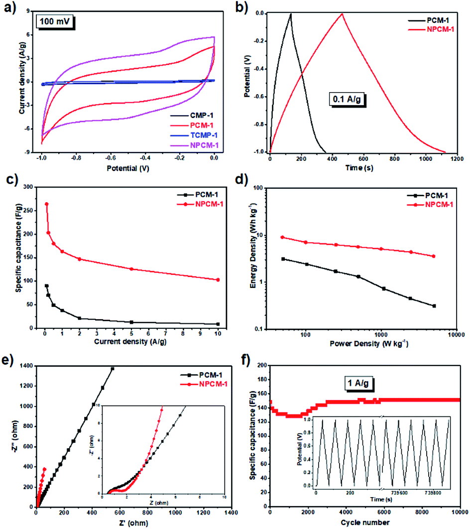 | ||
Fig. 4 (a) Cyclic voltammograms of CMPs and PCMs at the scan rate of 100 mV s−1, (b) galvanostatic charge–discharge curves of CMPs and PCMs at a current density of 0.1 A g−1, (c) gravimetric capacitances (Cs) of PCM-1 and NPCM-1 at different current densities, (d) Ragone plots of gravimetric energy density versus power density for PCM-1 and NPCM-1-based supercapacitors, (e) Nyquist plots with the inset showing the enlarged part of the high-frequency region, (f) capacitance of NPCM-1 for a 10![[thin space (1/6-em)]](https://www.rsc.org/images/entities/char_2009.gif) 000-cycle charge–discharge test at a current density of 1 A g−1, the inset shows the charge–discharge curves of NPCM-1 during a test of 10000 cycles. 000-cycle charge–discharge test at a current density of 1 A g−1, the inset shows the charge–discharge curves of NPCM-1 during a test of 10000 cycles. | ||
Galvanostatic charge−discharge (GCD) measurements were carried out to further evaluate the electrochemical performances of PCM-1 and NPCM-1. As shown in Fig. S8,† GCD curves of PCM-1 and NPCM-1 electrodes at different current densities exhibit triangular shapes with high symmetry and nearly linear slopes, corresponding to ideal electrochemical double layer capacitors and corroborating well with the CV curves.20 The specific capacitances at different current densities calculated based on the GCD curves of NPCM-1 (e.g. 264 F g−1 at 0.1 A g−1) are much higher than those of PCM-1 (e.g. 90 F g−1 at 0.1 A g−1) (Fig. 4b and c). The Ragone plot (Fig. 4d) reveals that NPCM-1 exhibits a maximum energy density of 9.0 W h kg−1, two times higher than that of PCM-1 (3.1 W h kg−1). The energy density of NPCM-1 remains at 3.6 W h kg−1 when the power density is elevated to 5.0 kW kg−1, while that of PCM-1 shows a dramatic decrease during the increase of power density (0.3 W h kg−1 at 5.0 kW kg−1). The significant improvement of specific capacitance and energy density of NPCM-1 compared with PCM-1 is probably due to the enhanced electron transportation ability and higher ion diffusion rate induced by nitrogen doping.19
Electrochemical impedance spectroscopy (EIS) measurements were conducted to investigate the kinetic behavior of the PCM electrodes. The Nyquist plots of PCM-1 and NPCM-1 show a small semicircle in the high frequency region and a straight sloped line in the low frequency range (Fig. 4e). The diameter of the semicircle corresponds to the charge transfer resistance (RCT) of the electrode materials.20 NPCM-1 possesses a RCT of 1.0 Ω, which is lower than that of PCM-1 (1.5 Ω). Furthermore, compared with PCM-1, NPCM-1 exhibits a more vertical curve at low-frequency region, indicating a better capacitive behavior and lower diffusion resistance of electrolyte ions onto the N-doped material. The lower overall resistance of NPCM-1 can be attributed to the improved surface wettability induced by nitrogen doping, which is beneficial for easier accessibility of electrolyte ions to the electrode.34 The long-term stability of NPCM-1 was investigated by cycling experiments at the current density of 1 A g−1. As demonstrated in Fig. 4f, although there are some fluctuations mainly caused by the activated process in the first 3000 cycles, the specific capacitance of NPCM-1 after 10000 cycles remains almost unchanged and the GCD curves retain the symmetry well through the entire testing cycles, indicating highly reversible electrochemical properties and outstanding long-term stability of the N-doped porous carbon material.
Conclusions
In summary, two PCMs (PCM-1 and N-doped NPCM-1) with comparable porosity were prepared by the carbonization of rationally designed CMP precursors with the same skeleton structure and different chemical compositions. Carbonized materials PCM-1 and NPCM-1 show much higher CO2 capture capabilities compared with their CMP precursors thanks to the optimized pore structure. Due to the cooperative effects of both nitrogen doping and small pore size, NPCM-1 shows a high CO2 adsorption capability of 3.9 mmol g−1 at 273 K and 1 bar, which is quite promising considering its moderate specific surface area. Meanwhile, NPCM-1 exhibits much better performance in supercapacitive energy storage than PCM-1 even though these two PCMs possess similar porosity structures, probably due to the much improved electrical and surface properties induced by nitrogen doping. Thus, NPCM-1 displays a decent specific capacitance of 264 F g−1 at the current density of 0.1 A g−1 and excellent cycling stability. Overall, we can conclude that carbonization is an efficient method to significantly improve the CO2 capture capability of CMP materials through the optimization of pore structure and nitrogen doping can be used as a highly favorable strategy to enhance the supercapacitive energy storage properties of porous carbon materials. This could potentially provide a rational design principle for the construction of high performance porous materials.Acknowledgements
This work is financially supported by National Natural Science Foundation of China (21404074, 21574087), Science and Technology Department of Sichuan province (2015JY0143) and China Postdoctoral Science Foundation (2015M570785).References
- M. E. Davis, Nature, 2002, 417, 813–821 CrossRef CAS PubMed.
- A. D. Roberts, X. Li and H. Zhang, Chem. Soc. Rev., 2014, 43, 4341–4356 RSC.
- A. Stein, Z. Wang and M. A. Fierke, Adv. Mater., 2009, 21, 265–293 CrossRef CAS.
- D. Kalderis, S. Bethanis, P. Paraskeva and E. Diamadopoulos, Bioresour. Technol., 2008, 99, 6809–6816 CrossRef CAS PubMed.
- P. T. Williams and A. R. Reed, Biomass Bioenergy, 2006, 30, 144–152 CrossRef CAS.
- B. Adeniran and R. Mokaya, J. Mater. Chem. A, 2015, 3, 5148–5161 CAS.
- Y. Zhu, S. Murali, M. D. Stoller, K. Ganesh, W. Cai, P. J. Ferreira, A. Pirkle, R. M. Wallace, K. A. Cychosz and M. Thommes, Science, 2011, 332, 1537–1541 CrossRef CAS PubMed.
- J. Dai, J. Yuan and P. Giannozzi, Appl. Phys. Lett., 2009, 95, 232105 CrossRef.
- E. Paek, A. J. Pak, K. E. Kweon and G. S. Hwang, J. Phys. Chem. C, 2013, 117, 5610–5616 CAS.
- E. Frackowiak, Phys. Chem. Chem. Phys., 2007, 9, 1774–1785 RSC.
- L. Zhang and X. Zhao, Chem. Soc. Rev., 2009, 38, 2520–2531 RSC.
- X. Liu and L. Dai, Nat. Rev. Mater., 2016, 1, 16064 CrossRef CAS.
- J. M. Lee, M. E. Briggs, T. Hasell and A. I. Cooper, Adv. Mater., 2016, 28, 9804–9810 CrossRef CAS PubMed.
- T. Ben, H. Ren, S. Ma, D. Cao, J. Lan, X. Jing, W. Wang, J. Xu, F. Deng and J. M. Simmons, Angew. Chem., 2009, 121, 9621–9624 CrossRef.
- A. I. Cooper, Adv. Mater., 2009, 21, 1291–1295 CrossRef CAS.
- L. Hao, J. Ning, B. Luo, B. Wang, Y. Zhang, Z. Tang, J. Yang, A. Thomas and L. Zhi, J. Am. Chem. Soc., 2014, 137, 219–225 CrossRef PubMed.
- C. D. Wood, B. Tan, A. Trewin, H. Niu, D. Bradshaw, M. J. Rosseinsky, Y. Z. Khimyak, N. L. Campbell, R. Kirk and E. Stöckel, Chem. Mater., 2007, 19, 2034–2048 CrossRef CAS.
- Y. Xu, S. Jin, H. Xu, A. Nagai and D. Jiang, Chem. Soc. Rev., 2013, 42, 8012–8031 RSC.
- J. M. Lee, T. Wu, B. M. Alston, M. E. Briggs, T. Hasell, C. Hu and A. I. Cooper, J. Mater. Chem. A, 2016, 4, 7665–7673 CAS.
- Y. Kou, Y. Xu, Z. Guo and D. Jiang, Angew. Chem., Int. Ed., 2011, 50, 8753–8757 CrossRef CAS PubMed.
- K. Yuan, P. Guo-Wang, T. Hu, L. Shi, R. Zeng, M. Forster, T. Pichler, Y. Chen and U. Scherf, Chem. Mater., 2015, 27, 7403–7411 CrossRef CAS.
- M. E. Bhosale, R. Illathvalappil, S. Kurungot and K. Krishnamoorthy, Chem. Commun., 2016, 52, 316–318 RSC.
- S. Ren, R. Dawson, A. Laybourn, J. Jiang, Y. Khimyak, D. J. Adams and A. I. Cooper, Polym. Chem., 2012, 3, 928–934 RSC.
- F. Tuinstra and J. L. Koenig, J. Chem. Phys., 1970, 53, 1126–1130 CrossRef CAS.
- Z. Luo, S. Lim, Z. Tian, J. Shang, L. Lai, B. MacDonald, C. Fu, Z. Shen, T. Yu and J. Lin, J. Mater. Chem., 2011, 21, 8038–8044 RSC.
- G. Li, Y. Li, H. Liu, Y. Guo, Y. Li and D. Zhu, Chem. Commun., 2010, 46, 3256–3258 RSC.
- L. Hao, B. Luo, X. Li, M. Jin, Y. Fang, Z. Tang, Y. Jia, M. Liang, A. Thomas and J. Yang, Energy Environ. Sci., 2012, 5, 9747–9751 CAS.
- K. S. Sing, Pure Appl. Chem., 1985, 57, 603–619 CrossRef CAS.
- S. Ren, M. J. Bojdys, R. Dawson, A. Laybourn, Y. Z. Khimyak, D. J. Adams and A. I. Cooper, Adv. Mater., 2012, 24, 2357–2361 CrossRef CAS PubMed.
- J. Jiang, F. Su, A. Trewin, C. D. Wood, H. Niu, J. T. Jones, Y. Z. Khimyak and A. I. Cooper, J. Am. Chem. Soc., 2008, 130, 7710–7720 CrossRef CAS PubMed.
- S. Hu, J. Xiang, L. Sun, M. Xu, J. Qiu and P. Fu, Fuel Process. Technol., 2008, 89, 1096–1105 CrossRef CAS.
- H. Wei, S. Deng, B. Hu, Z. Chen, B. Wang, J. Huang and G. Yu, ChemSusChem, 2012, 5, 2354–2360 CrossRef CAS PubMed.
- A. Alabadi, X. Yang, Z. Dong, Z. Li and B. Tan, J. Mater. Chem. A, 2014, 2, 11697–11705 CAS.
- X. Zhang, L. Ma, M. Gan, G. Fu, M. Jin, Y. Lei, P. Yang and M. Yan, J. Power Sources, 2017, 340, 22–31 CrossRef CAS.
Footnote |
| † Electronic supplementary information (ESI) available. See DOI: 10.1039/c7ra05551j |
| This journal is © The Royal Society of Chemistry 2017 |