 Open Access Article
Creative Commons Attribution 3.0 Unported Licence
Influence of the ultrasonic surface rolling process on stress corrosion cracking susceptibility of high strength pipeline steel in neutral pH environment
Bingying Wang *a,
Yu Yina,
Zhiwei Gaoa,
Zhenbo Houa and
Wenchun Jiangb
aCollege of Mechanical and Electronic Engineering, China, University of Petroleum (East China), Qingdao, Shandong 266580, China. E-mail: tdwby2004@126.com
bCollege of Chemical Engineering, China University of Petroleum (East China), Qingdao, Shandong 266580, China
First published on 25th July 2017
Abstract
A newly developed surface enhancement technique, ultrasonic surface rolling processing (USRP), was applied on X80 pipeline steel. Results from scanning electron microscopy (SEM), transmission electron microscopy (TEM), X-ray diffraction (XRD) and surface roughness testing indicated that the processing induced a plastic flow (120 μm deep) and a nano-structured layer, with a grain size of 40–100 nm. Surface roughness was reduced to 15% of the original specimen. Meanwhile, residual compression stress was achieved in the surface layer. The bent-beam stress-corrosion test showed that corrosion product scales of the USRP specimen were more compact together with a reduction in scale thickness. Compared with the original specimen, width of the stress corrosion cracks, roughness of the scale/steel interface and corrosion rate decreased after USRP. The effects of grain size and surface roughness as well as the stress field on stress corrosion cracking susceptibility of X80 pipeline steel treated by USRP were investigated.
1 Introduction
In most cases, material failures occur on surfaces as the majority of failures are sensitive to structure and properties of the material surface, such as fatigue fracture, wear and corrosion, etc. Therefore, the enhancement of surface properties can effectively improve the comprehensive performance of materials. As a newly developed surface modification technique, surface nanocrystallization is expected to significantly improve the overall properties of materials by generation of a nanostructured surface layer, which is also an effective method to fulfill special performance requirements localized at the surface of materials without changing the chemical compositions and shape of materials.1 At present, three kinds of techniques have been developed for synthesizing nanostructured surface layer: surface coating/deposition, surface self-nanocrystallization (SNC) and hybrid surface nanocrystallization.2 Compared with the other two methods, surface self-nanocrystallization has attracted extensive attention worldwide because of its economical efficiency, simplicity and good performance. For the moment, surface nanocrystallization technologies which have been successfully applied in practical engineering include ultrasonic shot peening (USP),1,3–6 ultrasonic impact treatment (UIT),7–9 laser shock processing (LSP)10–12 and ultrasonic surface rolling processing (USRP),13–16 etc. Lu et al. found that the mechanical and tribological properties of different materials were enhanced after ultrasonic shot peening.1–3 Ultrasonic impact treatment technology was invented by Statnikov7–9 in 1970, which was mainly used to improve the residual stress field of welding structures. Compared with the conventional surface enhancement techniques using surface plastic deformation (SPD), Montross et al.10–12 demonstrated that laser shock processing dramatically improved the surface hardness and fatigue property of 316L stainless steel and aluminium alloy.As a new surface-treatment method for surface nanocrystallization, USRP has been widely applied to various fields. It has been found that USRP can synthesize nanostructured surface layer,13–16 improve the mechanical property,16,17,23 increase the fatigue strength and wear resistance of different metals.16,18 Currently, the research about USRP is mainly focus on the effect of USRP on the microstructure characterization, mechanical capacity, friction and fatigue property of metals. Bozdana19–21 proposed ultrasonic deep cold rolling (UDCR), which combined the deep cold rolling process with ultrasonic vibrations. The influence of UDCR and conventional deep cold rolling on the stress field, surface roughness and surface micro-hardness of Ti–6Al–4V specimens were compared. Liu et al.22,23 developed a 3D finite element model (FEM) to predict the treatment conditions that lead to surface nanocrystallization. Simulated results of surface deformation, stress and strain were investigated to assess the formation of nanostructured layer. Wang et al.13,16,17 examined the microstructure of nano-layer of USRP specimen and carried out the wear and friction test to show the effectiveness and reliability of USRP. Cheng et al.24,25 proposed a novel thread fatigue property enhancement method, i.e. ultrasonic thread root rolling (UTRR) process. It is well proved by fatigue results that an increase of about 7 times for fatigue life of AerMer100 specimens is achieved after UTRR. Nevertheless, very little is known about the influence of USRP on the corrosion behavior, especially the stress corrosion cracking. Wang et al.26 studied the effect of USRP on stress corrosion cracking behaviors of X80 pipeline steel through the slow strain rate tensile tests (SSRT) and scanning electron microscopy. The previous studies have indicated that USRP virtually extended the fracture time and enhance the stress corrosion resistance of X80 pipeline steel, which is of great significance for the application of high strength pipeline steel. However, researches on the mechanism of the different SCC behavior of X80 pipeline steel with and without USRP treatment has yet to be further discussed.
In the present study, the bent-beam stress-corrosion test were carried out to investigate the stress corrosion cracking susceptibility of X80 pipeline steel treated by USRP. Corrosion products and crack morphology of bent-beam specimens with and without USRP were compared. The beneficial effect of USRP has been verified by stress-corrosion test results. In addition, the variation of grain sizes, surface roughness and residual stress field are examined on the specimens by transmission electron microscope (TEM), X-ray diffraction (XRD) and surface roughness test. Based on the experimental results, the effect of grain sizes, surface roughness and residual stress modification on SCC behavior of X80 steel is discussed.
2 Experimental procedure
2.1 Principles and application of USRP
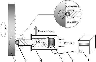
Fig. 1 shows configuration of USRP device, which consists of USRP operator and ultrasonic wave generator (frequency of 20 kHz). The USRP operator is composed of piezoelectric ceramic energy transducer, amplitude changing rod and working tip. The vibration energy of processing tip is supplied by ultrasonic wave generator, while the static pressure between work piece and USRP operator can be applied by spring fixed at the bottom or compressed air.13–15 In the course of ultrasonic surface rolling processing, the ultrasonic wave generator turns the ordinary alternating current (AC) into high-frequency AC (20 kHz). After that, the high-frequency AC (20 kHz) can be transformed into ultrasonic vibration through the piezoelectric ceramic energy transducer. Meanwhile, the amplitude changing rod will magnify the vibration. At last, under a certain feeding rate, static force and ultrasonic vibration are applied on the surface of high-speed spinning specimen through the working tip, which leads to severe elastic and plastic deformation in the surface layer because of the impact extrusion action.16,17,23 Technological parameters of the USRP in this paper were shown in Table 1.| Static force (N) | Spindle speed (rpm) | Feeding speed (mm min−1) | Frequency of vibration (kHz) | Amplitude of vibration/μm |
|---|---|---|---|---|
| 450 | 128 | 13.2 | 17.07 | 10 |
As is shown in eqn (1), the total force Fτ in USRP is the sum of static force and dynamic force, where Fsta is the static load, Fa the amplitude of dynamic load.24,25,27 The maximum force is the sum of static force and amplitude of dynamic force. As reported by Suh et al.,27 strength of the dynamic energy is 2.5–5 times larger than the static energy. Therefore, the USRP treatment exhibits unique characteristic of high energy input compared with the conventional rolling process, which results in larger plastic deformation than the static force applied alone. In addition, ratcheting then occurs for the root material as thousands of cyclic loading per second is applied on a small region of root surface. Ratcheting here is a cyclic accumulation of plastic deformation, which occurs under the stress-controlled cyclic loading with non-zero mean stress.28 Eqn (2) from previous paper of Cai et al. shows that plastic strain increases due to ratcheting, where εsr is saturated ratcheting strain related to maximum stress, α and β are material factors depended on stress status, and N is number of cycles for alternative stress.29 Thus, compared with other surface plastic deformation (SPD) method, severer plastic deformation and deeper enhanced layer can be generated through the USRP treatment.
Fτ = Fsta + Fa![[thin space (1/6-em)]](https://www.rsc.org/images/entities/char_2009.gif) sin(2πft) sin(2πft)
| (1) |
| εr = εsr(1 − αNβ) | (2) |
2.2 Test specimens
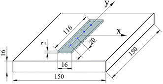
The X80 pipeline steel, which is widely used in oil and gas industry, is chosen as experimental materials. The chemical composition of X80 steel were 0.055% C, 1.3971% Mn, 0.26% Mo, 0.256% Ni, 0.22% Si, 0.0318% Cr, 0.055% Nb, 0.015% Ti, 0.044% Al, 0.007% N, 0.0017% P, 0.0019% S in wt%. The mechanical properties were as follows: yield strength 610 MPa, tensile strength 725 MPa, yield ratio 0.816, and elongation 38%. As shown in Fig. 2, two plate specimens of 150 × 150 × 16 mm3 were prepared, of which the surfaces were first polished with silicon carbide papers. For following contrast experiments, only one of the specimen surfaces was treated by the USRP device. After USRP, the microstructure and grain size of the surface layer on the specimen were characterized by optical microscopy (OM) and field emission gun TEM (JEOL 2100). Specimens for TEM observations were cut from the treated surface layer by wire electrical discharge machining (WEDM) and thinned by ion-beam milling system (Bal-Tec RES101).2.3 Measurement of surface roughness and residual stress
The surface roughness of USRP and original specimens was examined by a TR200 surface roughness tester. As the stress-corrosion test needed to be carried out after residual stress test, a non-destructive method (X-ray diffraction method) was chosen to test the surface residual stress of specimens with and without USRP. As shown in Fig. 2, four blue points are the measuring positions and the gray area is specimen positions of stress-corrosion test. The transverse (X-direction) and longitudinal (Y-direction) residual stress of four test points on the specimen surface with and without USRP were measured respectively by Rigaku D/max 2550V X-ray tester using fixed ψ0 method. The XRD parameters were as follows: characteristic spectral line Co-Kα, operating voltage of X-ray tube 30 kV, operating current 6–8 mA, and ψ0: 0°, 15°, 30°, 45°.2.4 Bent-beam stress-corrosion test
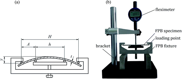
According to ASTM G39, the effects of USRP on SCC susceptibility of X80 pipeline steel were evaluated using four-point bending test. Two four-point bending (FPB) specimens were cut off from plate specimens with and without USRP treatment (see Fig. 2). As shown in Fig. 3a, the FPB fixture was used to fix the FPB specimens, which was 116 × 16 × 2 mm3 in size. Detail of the FPB specimens, FPB fixture and fleximeter were presented in Fig. 3b. The deflection of FPB specimens was calculated by eqn (3), where σ was the maximal tension stress of specimens, E was the elastic modulus, t was the thickness of specimens, y was the deflection of specimen, H and A were the distances between loading points.| σ = 12Ety/(3H2 − 4A2) | (3) |
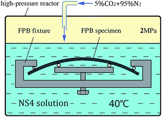
To simulate the stress corrosion cracking of X80 pipeline steel with and without USRP treatment in neutral pH solutions, two FPB fixture with FPB specimens were placed in a high-pressure reactor, as schematically shown in Fig. 4. The experimental medium was NS4 solution (0.483 g L−1 NaHCO3; 0.122 g L−1 KCL; 0.181 g L−1 CaCl·2H2O; 0.131 g L−1 MgSO4·7H2O), which was used to simulate the near neutral soil solution. 5% CO2 and 95% N2 gas were bubbled into the NS4 solution with temperature 20 °C and pressure 2 MPa. Corrosion products of the specimens were removed for weighing every five days. Meanwhile, the experimental medium was replaced. The total length of the FPB test was 20 days. The corrosion rates were calculated by eqn (4), where v was the corrosion rate, m0 was the weight of original specimen, m was the weight of specimen after corrosion, S was the surface area of specimen, t was the test time.
 | (4) |
3 Results
3.1 Microstructure analysis
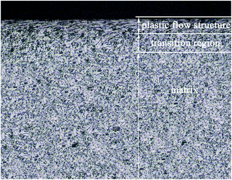
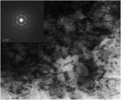
As can be seen from the cross-section metallograph of USRP specimen (Fig. 5), plastic flow is formed on the surface after USRP. The thickness of flow structure is about 120 μm. Besides, the plastic deformation decreases gradually along depth from surface. The microstructure of X80 steel is mainly made up of acicular ferrite and bainitic, both of which are body-center-cubic (BCC) structure. As material with bcc structure consists of 48 slip systems, severe plastic deformation caused by USRP leads to multiple slip and cross slip in different direction, which is also the forming reason of plastic flow layer. Meanwhile, Fig. 6 indicates that sizes of equiaxed grains on the surface of X80 steel are refined to 40–100 nm and there exist a certain degree of unevenness grains.33 Moreover, selected area electron diffraction (SAED) patterns shows that these nano-grains possess random crystallographic orientations, which is similar to the tendency of a pure Fe and 316L stainless steel plate after ultrasonic shot peening (USP) treatment.3,4It is considered that, grain refinement during USRP is primarily induced by plastic deformation. As X80 steel is of high fault energy and dislocation density, the dominant model of plastic deformation is dislocation slip. The dislocation density of grains increases with strain. In order to reduce system energy, dense dislocations tangle together and form cellular structures (with geometric grain boundaries) through slip, accumulation, interaction, annihilation and rearrangement.16 After that, cellular structures will develop into subgrains (with independent slip systems). While strain keeps increasing, subgrains turn to new grains with small or big angle grain boundaries. When the generating and annihilating rate of dislocations become equilibrium, grain size becomes stable and equiaxed nano-grains possessing random orientations are formed.30,31
3.2 Surface roughness analysis
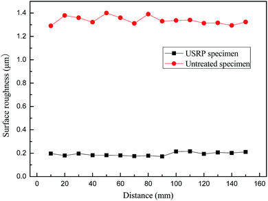
As shown in Fig. 7, the surface roughness decreases significantly after USRP treatment. Ra of untreated specimen fluctuates around 1.3 μm, while that of USRP specimen is about 0.2 μm, which is 15% of untreated specimen. According to the analysis, the plastic flow induced by USRP treatment makes wave trough of surface filled by wave crest, which decreases the surface roughness of X80 specimen.3.3 Residual stress analysis
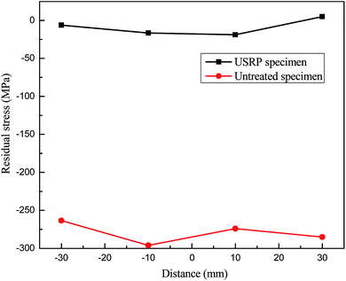
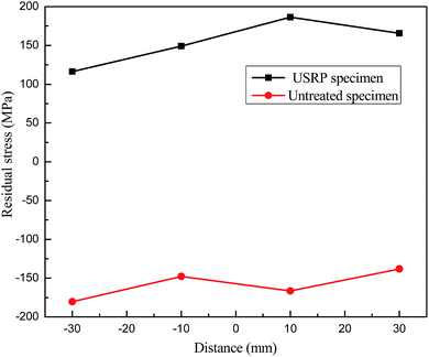
Fig. 8 and 9 shows the variations of both longitudinal and transverse residual stress on the specimen surface with and without USRP treatment. It can be seen that residual stress field on the specimen surface is improved by USRP treatment. The residual stress remarkably changes from tensile to compressive after USRP, and the original compressive residual stress also increases significantly. As indicated in Fig. 8, the maximum compressive residual stress is −296.07 MPa, which is almost 48.5% σs. From Fig. 9, it can be calculated that the maximum variable quantity of longitudinal residual stress is 353.03 MPa. It is well known that the compressive residual stress on the specimen surface is induced by severe plastic deformation after USRP.113.4 Stress corrosion analysis
The electrode reactions of X80 pipeline steel in NS4 solution are as follows.34,35
3.4.3.1 Anodic reaction:.
| Fe → Fe2+ + 2e | (5) |
| Fe2+ + CO32− → FeCO3 | (6) |
3.4.3.2 Cathodic reaction:.
| H+ + e → H | (7) |
| H2CO3 + e → H + HCO3− | (8) |
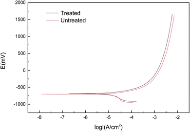
| Specimens | Ecorr/V | βa | βc | Rp/Ω | Icorr/μA cm−2 |
|---|---|---|---|---|---|
| Untreated | −0.701 | 0.105 | 0.433 | 938 | 56.54 |
| Treated | −0.686 | 0.108 | 0.422 | 1000 | 32.00 |
At cathodic potentials, when the hydrogen concentration reaches a critical value, hydrogen induced cracking controls the cracking process.39 Hydrogen-induced cracks generally originate from the presence of more manganese sulfide inclusions and some complex carbon–nitrogen compound particles. And these cracks are more easily expanded along high-angle crystal orientations such as {110}//ND and {111}//ND. Since the fine-grained region has more nodes and structural defects, it is possible to increase the hydrogen-induced crack susceptibility by hindering the diffusion of hydrogen. The electrochemical behavior of the specimens before and after USRP treatment has been compared.41 It was found that the specimens treated by USRP had a corrosion potential greater than that of untreated specimens. Moreover, the treated specimen has a residual compressive stress on the surface, which is not conductive to the diffusion of hydrogen into the interior of the matrix. To a certain extent, the residual compressive stress would reduce the hydrogen-induced crack susceptibility.42–45 The creak nucleation in the experiment environment is the anodic dissolution process promoted by hydrogen. Hydrogen easily converges to high stress zones, promoting localized plastic deformation by reducing the bond between metal atoms. So that the critical sizes of the cracks are reduced. Under the action tensile stress, the metal matrix slips. In the meantime, the passivation film breaks down to form local dissolution, which promotes the dissolution of the metal cation and makes the microcracks more easily nucleated here.
4 Discussion
4.1 Effect of surface roughness
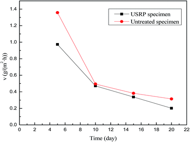
Generally, the surface roughness plays an a critical role in the corrosion behaviour of metallic materials. The contact area of corrosive medium and metallic materials increases with the surface roughness. In addition, corrosive medium tend to deposit on rough surface, which leads to intenser permeability and corrosion. However, the impact and squeezing action of USRP treatment makes wave trough of surface filled by wave crest, which decreases the surface roughness and eliminate the scratches of material surface. Therefore, the micro surface defects which induce etch pits can be removed by USRP to some extent. Based on electrochemical test results, Walter et al.46 reported that the corrosion current and the pitting tendency of magnesium alloy increased with the surface roughness. Researches on corrosion behavior of copper in 3.5% NaCl solution47 have theoretically demonstrated that roughness can increase the fluctuation of the electron work function (EWF). Such fluctuation could promote the formation of microelectrodes and, therefore, accelerate corrosion. Based on the above analysis, combined with Fig. 10 and 11, it can be concluded that the USRP treatment can decrease the corrosion rate and the pitting tendency through improving the smoothness of X80 pipeline steel.4.2 Effect of grain refinement
According to the TEM results (Fig. 6), the USRP treatment leads to surface nanocrystallization of X80 pipeline steel, which increase the volume fraction of grain boundaries in the surface layer.48 For one thing, dense grain boundaries provide high-density diffusion path for Ni, Cr, Mo, etc. The diffusion coefficient can be improved by 7–9 orders of magnitude.49 Besides, the plastic deformation induced by USRP treatment homogenizes these elements, which is promotes the formation of dense and uniform passive films. For another, the nanocrystalline layer hinders dislocation motion, which prevents the rupture of passive films.In the stage of crack propagation, the hydrogen induced cracking controls the cracking process when the hydrogen concentration reaches a critical value.40 However, previous work by P. F. Feng and J. H. He shows that the susceptibility to hydrogen induced cracking of steels decreases with decreasing grain size.50,51 Meanwhile, as adjoining grains having different crystallographic orientations, the propagation direction will change when cracks penetrate the grain boundaries, which will consume more energy. Therefore, the increasing of the volume fraction of grain boundaries can restrain the crack propagation.
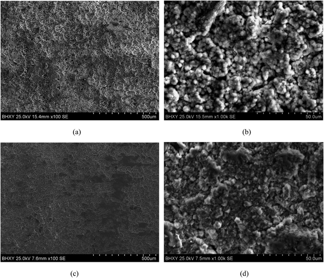
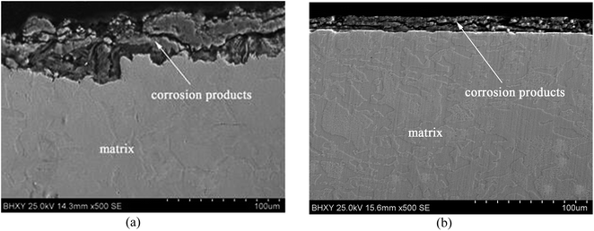
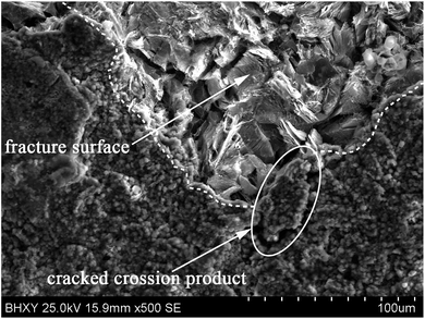
The grain refinement induced by USRP treatment lead to a more compact and uniform corrosion scale (Fig. 12b), which inhibits the corrosion of metallic matrix (Fig. 10). However, the corrosion products of untreated specimen are relatively loose (Fig. 12a). Moreover, H2, the product of the catholic reaction of X80 steel in NS4 solution will gather in the interface between the matrix and corrosion scale. The concentrations of hydrogen and uneven growth of corrosion production will lead to stress concentration, which consequently separate the corrosion scale. After separation, new surface of X80 steels are exposed to the corrosive medium and lead to potential difference. Therefore, the local galvanic corrosion cause non-uniform corrosion of untreated specimen and make the interface between matrix and corrosion scale irregular, as shown in Fig. 12a.
4.3 Effect of residual stress
As Fig. 8 and 9 shows, the USRP treatment generates a residual compressive stress field in the surface of X80 specimen. In the initiation stage of SCC, the nucleation of micro cracks is controlled by anodic dissolution. The residual compressive stress can decrease the driving force of crack nucleation and suppress the crack initiation. Chu et al.52 illustrated that compressive stress can also cause SCC. However, its incubation period is one or two orders higher, and the threshold value are three to five times more than that of tensile stress. In addition, hydrogen is unable to diffuse and gather through the induction of stress in compression stress field. Therefore, hydrogen induced cracking won't happen under compressive stress states. Liu's research53 on intergranular corrosion (IGC) of AA2024-T3 shows that the application of compressive stress at a level halfway to yield significantly reduced the growth kinetics of IGC, and the electrochemical measurements show that the passive current density decrease for specimens with compressive residual stress. The compressive residual stress is more effective in resisting the infiltration of corrosive agents at an early stage of corrosion development.54 Therefore, residual compressive stress induced by USRP treatment restrains the hydrogen diffusion and the crack propagation, which decrease the SCC susceptibility of X80 pipeline steel to a certain extent.5 Conclusions
(1) Plastic flow is formed on the surface of X80 pipeline steel after USRP treatment, with a thickness of 150 μm. Sizes of equiaxed grains on the surface of X80 specimen are refined to 40–100 nm and the nano-grains possess random crystallographic orientations.(2) After the USRP treatment, the Ra of specimen decreased to 0.2 μm, which is 15% of untreated specimen. Meanwhile, the residual stress remarkably changes from tensile to compressive, and the original compressive residual stress also increases significantly. The maximum compressive residual stress is about −296.07 MPa.
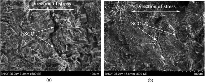
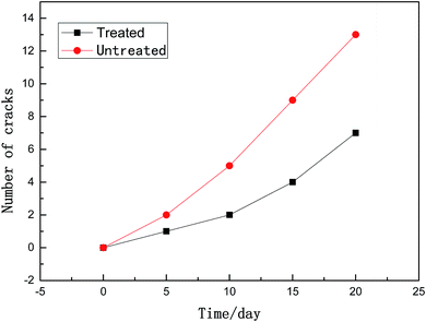
(3) The USRP treatment can reduce the corrosion rate and restrain the propagation of cracks on X80 specimen in neutral pH environment. Compared with untreated specimen, the corrosion scale of USRP specimen is homogenous and dense (with a thinner thickness), and the interface between corrosion products and metallic matrix is more smooth. In addition, the stress corrosion crack in the USRP specimen is narrower than that of untreated specimen.
Conflict of interest
The authors declare that they have no conflict of interest.References
- K. Lu and J. Lu, Mater. Sci. Eng., A, 2004, 375–377, 38–45 CrossRef.
- L. U. Ke and L. U. Jian, Mater. Sci. Res. Int., 1999, 15, 193–197 Search PubMed.
- G. Liu, J. Lu and K. Lu, Mater. Sci. Eng., A, 2000, 286, 91–95 CrossRef.
- N. R. Tao, M. L. Sui, J. Lu and K. Lua, Nanostruct. Mater., 1999, 11, 433–440 CrossRef CAS.
- J. Badreddine, E. Rouhaud, M. Micoulaut and S. Remy, Int. J. Mech. Sci., 2014, 82, 179–190 CrossRef.
- F. Yin, L. Hua and X. Wang, Comput. Mater. Sci., 2014, 92, 28–35 CrossRef CAS.
- E. S. Statnikov, IIW/IIS, 1997, Doc.XII-1667–97.
- S. Roy, J. W. Fisher and B. T. Yen, Int. J. Fatigue, 2003, 25, 1239–1247 CrossRef CAS.
- X. Cheng, J. W. Fisher, H. J. Prask, T. Gnäupel-Herold, B. T. Yen and S. Roy, Int. J. Fatigue, 2003, 25, 1259–1269 CrossRef CAS.
- C. S. Montross, T. Wei, L. Ye, G. Clark and Y. W. Mai, Int. J. Fatigue, 2002, 24, 1021–1036 CrossRef CAS.
- Y. Zhang, J. You, J. Lu, C. Cui, Y. Jiang and X. Ren, Surf. Coat. Technol., 2010, 204, 3947–3953 CrossRef CAS.
- P. Peyre, R. Fabbro, P. Merrien and H. P. Lieurade, Mater. Sci. Eng., A, 1996, 210, 102–113 CrossRef.
- T. Wang, D. Wang, G. Liu, B. Gong and N. Song, J. Mater. Eng., 2009, 45, 177–183 CAS.
- Y. Liu, D. P. Wang, C. Y. Deng and S. Cao, J. Mater. Eng., 2015, 43, 8–13 Search PubMed.
- G. Y. Mei, K. H. Zhang, J. F. Ding and G. Y. Mei, Adv. Mater. Res., 2010, 102–104, 591–594 CrossRef CAS.
- T. Wang, D. Wang, G. Liu, B. Gong and N. Song, Appl. Surf. Sci., 2008, 255, 1824–1829 CrossRef CAS.
- T. Wang, D. P. Wang, G. Liu, B. M. Gong and N. X. Song, J. Mater. Eng., 2009, 45, 177–183 CAS.
- Z. B. Wang, N. R. Tao, S. Li, W. Wang, G. Liu and J. Lu, Mater. Sci. Eng., A, 2003, 352, 144–149 CrossRef.
- A. T. Bozdana, N. N. Z. Gindy and H. Li, Int. J. Mach. Tool Manufact., 2005, 45, 713–718 CrossRef.
- A. T. Bozdana and N. N. Z. Gindy, Mater. Sci. Technol., 2008, 24, 1378–1384 CrossRef CAS.
- A. T. Bozdana, Surface enhancement of Ti-6Al-4V using conventional and ultrasonic deep cold rolling processes, University of Nottingham, 2006 Search PubMed.
- Y. Liu, X. Zhao and D. Wang, Mater. Sci. Eng., A, 2014, 600, 21–31 CrossRef CAS.
- Y. Liu, L. Wang and D. Wang, J. Mater. Res., 2011, 211, 2106–2113 CAS.
- M. L. Cheng, D. Y. Zhang, H. W. Chen and W. Qin, J. Mater. Res., 2014, 214, 2395–2401 CAS.
- M. L. Cheng, D. Y. Zhang, H. W. Chen, W. Qin and J. S. Li, Int. J. Adv. Des. Manuf. Technol., 2016, 83, 123–131 Search PubMed.
- B. Y. Wang, Y. Miao, S. Zhou and Z. B. Hou, Trans. China Weld. Inst., 2013, 34, 81–84 CAS.
- C. M. Suh, G. H. Song, M. S. Suh and Y. S. Pyoun, Mater. Sci. Eng., A, 2007, 443, 101–106 CrossRef.
- S. Bari and T. Hassan, Int. J. Plast., 2002, 18, 873–894 CrossRef.
- L. X. Cai, H. F. Luo and Q. Gao, CIESC J., 2002, 23, 17–22 Search PubMed.
- J. Y. Huang, Y. T. Zhu, H. Jiang and T. C. Lowe, Acta Mater., 2001, 49, 1497–1505 CrossRef CAS.
- X. Wu, N. Tao, Y. Hong, B. Xu, J. Lu and K. Lu, Acta Mater., 2002, 50, 2075–2084 CrossRef CAS.
- L. Wang, X. Li and C. Du, J. Iron Steel Res. Int., 2015, 22, 135–144 CrossRef.
- R. Z. Valiev, A. V. Korznikov and R. R. Mulyukov, Mater. Sci. Eng., A, 1993, 168, 141–148 CrossRef.
- B. Gu, J. L. Luo, W. Z. Yu and X. Mao, Corrosion, 1999, 55, 312–318 CrossRef CAS.
- B. Y. Wang, L. X. Huo, D. P. Wang and C. Y. Deng, J. Tianjin Univ., 2007, 40, 757–760 CAS.
- W. Chen, F. King, T. R. Jack and M. J. Wilmott, Metall. Mater. Trans. A, 2002, 33, 1429–1436 CrossRef.
- A. Plumtree, B. W. Williams, S. B. Lambert and R. Sutherby, SCC growth in pipeline steel, 2008, pp. 199–210 Search PubMed.
- R. B. Rebak, Z. Xia, R. Safruddin and Z. Szklarskasmialowska, Corrosion, 1996, 52, 396–405 CrossRef CAS.
- R. N. Parkins, W. K. Blanchard and B. S. Delanty, Corrosion, 1994, 50, 394–408 CrossRef CAS.
- B. Y. Fang, A. Atrens, J. Q. Wang, E. H. Han, Z. Y. Zhu and W. Ke, J. Mater. Sci., 2003, 38, 127–132 CrossRef CAS.
- B. Y. Wang, S. S. Si and Y. Miao, T. Mater. Heat. Treat., 2014, 35, 206–209 CAS.
- M. Masoumi, C. C. Silva and H. F. G. de Abreu, Corros. Sci., 2016, 111, 121–131 CrossRef CAS.
- M. A. Mohtadi-Bonab, J. A. Szpunar and R. Basu, Int. J. Hydrogen Energy, 2015, 40, 1096–1107 CrossRef CAS.
- M. A. Mohtadi-Bonab and M. Eskandari, Eng. Failure Anal., 2017, 79, 351–360 CrossRef CAS.
- A. Egbewande, W. Chen, R. Eadie, R. Kania, G. V. Boven and R. Worthingham, Corros. Sci., 2014, 83, 343–354 CrossRef CAS.
- R. Walter and M. B. Kannan, Mater. Des., 2011, 32, 2350–2354 CrossRef CAS.
- W. Li and D. Y. Li, Acta Mater., 2006, 54, 445–452 CrossRef CAS.
- H. Wang, G. Song and G. Tang, Surf. Coat. Technol., 2015, 282, 149–154 CrossRef CAS.
- W. Ye, Y. Li and F. Wang, Electrochim. Acta, 2006, 51, 4426–4432 CrossRef CAS.
- P. F. Feng, C. F. Li, D. M. Gong, W. Z. Shen, G. J. Chen and A. H. Fu, Corros. Sci. Prot. Technol., 2012, 33, 12–15 CAS.
- J. H. He, X. Y. Tang and N. P. Chen, Acta Metall., 1991, 1, 21–24 Search PubMed.
- W. Y. Chu, L. J. Qiao and J. M. Xiao, J. Univ. Sci. Technol. Beijing, 1992, 14(2), 212–219 CAS.
- X. Liu and G. S. Frankel, Corros. Sci., 2006, 48, 3309–3329 CrossRef CAS.
- M. S. Ahmed, P. Munroe, Z. T. Jiang, X. Zhao, W. Rickard and Z. F. Zhou, Corros. Sci., 2011, 53, 3678–3687 CrossRef CAS.
| This journal is © The Royal Society of Chemistry 2017 |

