
 Open Access Article
 This Open Access Article is licensed under a Creative Commons Attribution-Non Commercial 3.0 Unported Licence
Promotion of hydrogenation activity and sulfur resistance over Ni/ASA catalyst by support modification simultaneously with P and USY†
Sha Cui,
Jiaqi Ge,
Genggeng Wang,
Ying Yang and
Baijun Liu *
*
State Key Laboratory of Heavy Oil Processing, College of Chemical Engineering, China University of Petroleum, Beijing 102249, People's Republic of China. E-mail: bjliu2017@163.com; Tel: +86 18911226182
First published on 25th August 2017
Abstract
Individual and simultaneous P and USY promoted amorphous SiO2–Al2O3 (ASA) supported Ni catalysts were prepared using the hydrothermal synthesis method with the assistance of cis-9-octadecenylamine. The catalysts were characterized by X-ray diffraction (XRD), N2-adsorption and desorption, UV-vis diffuse reflectance spectroscopy, FTIR spectroscopy of adsorbed pyridine (Py-IR), transmission electron microscopy (TEM), temperature-programmed hydrogen reduction (H2-TPR) and X-ray photoelectron spectroscopy (XPS). The effects of P and USY loading on the activity of naphthalene hydrogenation were evaluated in a fixed bed reactor under the following reaction conditions: P = 4 MPa, GHSV = 16 h−1, H2/oil = 600 volume ratio, T = 200, 240, 280 and 320 °C. Experimental results verified that all individual P and USY modified catalysts displayed higher hydrogenation activity than the freely P and USY decorated catalyst at 200–280 °C. Furthermore, the catalyst simultaneously modified with 1.0 wt% P and 10 wt% USY had the highest hydrogenation activity and sulfur tolerance. Multiple effects, such as metal dispersion, acid amount, surface exposure of the active Ni° species and the [NiOh2+]/[NiTd2+] ratio were responsible for the high hydrogenation activity of P and USY-promoted catalysts.
1. Introduction
Aromatics in diesel, particularly polycyclic aromatic hydrocarbons (PAHs), can not only result in potential hazardous and carcinogenic effects,1 but can also increase the particle emissions from diesel engines, a primary factor in the elevation of the PM2.5 value2,3 and nitrogen oxides in the exhaust gas of automobiles. It is well known that when the aromatic content increases from 10% to 35%, particle emissions increase from 8.1% to 12.9%; moreover, hydrocarbons (HC), CO and NOx emissions also grow. Moreover, the aromatics widely distributed in diesel fuel seriously influence its quality, resulting in poor combustion performance and low cetane number (CN).4 Cooper et al.5 found that the cetane number of diesel fuel increased from 37 at an aromatic content of 37% to 48 when the aromatic content decreased to 20%. Therefore, the content of PAHs decreased from 11% in the European standard V to less than 7% in the European standard VI. It was reported that more than 30% of the diesel fuels in our country come from fluid catalytic cracking diesel oil (FCC) whose density is high and cetane number is low, which is due to over 70% aromatics existing in FCC diesel oil; thus, it is vital to decrease aromatic content.Catalytic hydrogenation to reduce aromatic content is the most efficient route6,7 and is also commonly used in industry. Hydrofining and hydrocracking are the two main methods for hydrogenation at home and abroad. Although the cetane value of diesel oil can be increased to a great extent by hydrocracking, the relatively low yield, high hydrogen consumption and expensive operating costs make hydrocracking disadvantageous. Therefore, hydrofining is still an important technique in removing aromatics.
Typically, transition metal catalysts supported on alumina are applied to the hydrogenation process. However, alumina, due to low Brønsted acidity8 and overly strong metal–support interaction,9 which decreases the reducibility and prevents the formation of active phases in the corresponding catalyst, has been replaced by other supports.10 In this sense, amorphous silica-alumina (ASA), as a composite carrier, possesses more acid sites11 and mezzo metal–support interaction,12 and its preparation procedure is simple, and the preparation cycle is short; thus, it is often applied to hydrogenation. There have been some studies13,14 that have provided evidence that ASA supported catalysts exhibit higher hydrogenation activity and improved sulfur tolerance relative to alumina supported catalysts.
Molecular sieves with high surface area and proper pore size as well as more acid sites are also potential supports of hydrogenation catalysts.15–17 Although hydrogenation activity was enhanced on zeolite supported catalysts, coke formation and overcracking were boosted due to the greater number of acid sites on zeolite.16 Moreover, a composite ASA–USY (ultra-stable Y zeolite) material used for the hydrocracking process has been reported, since it combines the advantages of the Y zeolite and ASA, obtaining modified acid properties and pore structure and providing high activity.18,19 Moreover, the aromatic hydrogenation activity of an alumina supported noble metal catalyst was also promoted by the addition of USY due to high acidity and metal dispersion.20 This prompted us to study the naphthalene hydrogenation reaction using the ASA support by adding a small amount of USY under the precondition of no cracking. It is also well known that phosphorus, as a type of catalytic additive, can change the characteristics of catalysts, such as surface acidity, metal dispersion and metal electro negativity, followed by altering hydrogenation activity.21–23 However, the P effect on the hydrogenation process is still controversial. Some literature studies reported that the influence of phosphorus is not detectable or negative.24,25 Other studies reported a positive effect of P addition to alumina25–27 or mesoporous silica28,29 supported catalysts, particularly for the hydrodesulfurization (HDS) and the hydrodenitrogenation (HDN) reactions.
Even though the USY and P modification in catalysts is found to have some effects on the hydrogenation process, there are no studies for individual and simultaneous USY and P modified nickel catalysts using amorphous SiO2–Al2O3 (ASA) as supports. In previous studies, several authors have suggested that macromolecular surface active or dispersion agents, such as Tween-80 (T-80), polyethylene glycol (PEG), polyvinyl alcohol (PVA) and polyoxyethylene octyl phenol ether-10 (OP-10) et al., could be added to the catalysts to efficiently improve dispersion and catalytic activity. Furthermore, the addition of chelating agents to enhance dispersion through the formation of clathrates with the metal to improve catalytic activity was also studied. In addition, Daniele Nicosia and Roel Prins30 also found that the synergistic effect of phosphorus and glycol additives was more favorable for HDS.
Hence, in this present study, ASA materials with high specific surface area (524 m2 g−1) and large pore volume (1.755 cm3 g−1) were prepared in our laboratory, and the ASA supported nickel catalysts, by support modification with individual and simultaneous phosphorus and USY, were prepared using the hydrothermal synthesis method with the assistance of cis-9-octadecenylamine. cis-9-Octadecenylamine, as a coordination and surface active agent, can form a Ni-cis-9-octadecenylamine complex with a nickel salt under hydrothermal condition, which boosts the dispersion of nanoparticles. Several authors have successfully prepared the metal oxide,31 noble metal32 and nickel phosphide nanoparticles33,34 with better dispersion using the hydrothermal method with the assistance of cis-9-octadecenylamine. The influence of the ASA support modification with individual and simultaneous phosphorus and USY was tested on naphthalene hydrogenation and sulfur tolerance of the nickel catalysts and correlated with physical–chemical properties.
2. Experimental
2.1. Support preparation
A procedure for the synthesis of ASA involved the following steps: with continuous stirring, an Al2(SO4)3 solution and NH3·H2O were simultaneously added to a bath solution with optimal pH, yielding an alumigel precipitate. After that, the water glass was added and the sample was transferred to a stainless-steel autoclave of seal aging at 80 °C for 3 h. This seal aging process helps to stabilize the pH value of the system. Next, the sample was filtered, washed and dried to obtain amorphous silica-alumina (ASA) with a Si/Al molar ratio of 1.5. The support modified with USY (Si/Al molar ratio = 15, 522 m2 g−1, 0.659 cm3 g−1) was prepared by mechanically blending USY and ASA. The as-prepared ASA and ASA–USY were mixed with the right amount of binders, adhesives and distilled water according to a certain mixing ratio, extruded, dried and calcined at 500 °C for 3 h. The calcined materials were ground and screened to select 20–40 mesh objective particles. Furthermore, the P-doped ASA and ASA–USY supports were prepared by the saturated volume impregnation method. In detail, the ASA and ASA–USY supports were impregnated with aqueous solutions of (NH4)2HPO4 with various P loadings. After the impregnation was completed, the samples were dried at 120 °C for 12 h and finally calcined at 500 °C for 3 h.2.2. Catalyst preparation
The catalysts were prepared via the hydrothermal synthesis method with the assistance of cis-9-octadecenylamine. The preparation was as follows: 10.96 g Ni(NO3)2·6H2O was dissolved in 50 mL deionized water and ethanol solution in an autoclave, and then a more substantial amount of mixture solution of cis-9-octadecenylamine and ethanol was added to the nickel nitrate solution under rotation. After the homogeneous mixed solution was formed, 20 g of support was added. Next, the autoclave was heated to 150 °C and leveled off for 12 h under sealing. Finally, the obtained composite was filtered, washed, dried and calcined at 500 °C for 3 h to obtain the oxidic catalyst. Herein, the catalysts with P loading of 0.0 wt%, 0.5 wt%, 1.0 wt%, 1.5 wt% and 2.0 wt% were labeled as Cat, Cat-0.5P, Cat-1.0P, Cat-1.5P and Cat-2.0P, respectively, the catalysts with a USY content of 10 wt% and 20 wt% were denoted as Cat-10USY and Cat-20USY, respectively, and the catalyst modified with 1.0 wt% P and 10 wt% USY simultaneously was denoted as Cat-1.0P-10USY, where the initial Ni loading was fixed at 10 wt% in all catalysts.2.3. Catalyst characterization
XRD analysis was performed using a Bruker AXSD8 Advance X-ray diffractometer with nickel-filtered Cu Kα X-ray radiation at 40 kV and 30 mA. The 2θ range was scanned from 10° to 80° with a scanning rate of 2° min−1. The assignment of crystalline phases is on the basis of the powder diffraction file cards. The dispersion is decided by the altitude of the diffraction peak.The specific surface area, pore volume and pore size were determined using a Bilder KuboX1000 system from the nitrogen adsorption–desorption isotherms at liquid nitrogen temperature. Prior to the measurement, the samples were outgassed in vacuum at 300 °C for 3 h. The specific surface area is determined based on the theory of BET. The total pore volume of micropores and mesopores was calculated from the amounts of nitrogen adsorbed at P/P0 = 0.98. Moreover, the pore size is obtained using the BJH method.
The UV-vis diffuse reflectance spectroscopy (DRS) was conducted on a UV-vis spectrophotometer (Hitachi U-4100) with an integration sphere diffuse reflectance attachment. Before measurement of the catalysts, the pure ASA support was tested. Then, the powder catalysts were placed into a quartz cell and the spectra were recorded in 200–800 nm with the ASA support as the baseline.
Temperature-programmed ammonia desorption (NH3-TPD) and temperature-programmed hydrogen reduction (H2-TPR) of the catalysts were measured on a TP 5079 analyzer. NH3-TPD is used to examine the acidity, and H2-TPR is carried out to analyze the reducibility of all oxidative catalysts. A total of 200 mg of catalyst was placed in a quartz reactor and pretreated at 400 °C to remove surface adsorption of impurities. The pretreated catalysts were exposed to ammonia for 20 min at 30 °C to ensure adsorption saturation. When the weakly adsorbed ammonia was removed, the NH3-TPD profile was recorded from 100 °C to 600 °C at a heating rate of 10 °C min−1. For the TPR measurement, after the samples were pretreated, the 200 mg catalysts were reduced in situ in flowing 5% H2/Ar by heating from ambient temperature to 850 °C at a constant rate of 10 °C min−1. Then, the TPR profiles were completed.
Fourier transform infrared spectroscopy analysis of adsorbed pyridine (Py-IR) was carried out using a Magna-IR 560 ESP spectrophotometer. The catalysts were pretreated for 1 h at 400 °C in vacuum and then cooled to 100 °C for pyridine adsorption. Py-IR spectra were recorded in the range of 1600–1400 cm−1 at 200 and 350 °C. The data obtained at 200 °C are categorized as total acid and 350 °C as the medium and strong acid.
The morphologies and dispersion of active metals were acquired on a JEM-2100 LaB6 high resolution transmission electron microscope equipped with maximum acceleration voltage of 200 kV, amplification factor of 50×–1500×, sample maximum inclination angle of ±35° and energy spectrometer element of 5 B–92 U. Prior to analysis, the sample was scattered around the ethanol solution, treated for 15–20 min via ultrasonication and suspended on the thin carbon film.
X-ray photoelectron spectroscopy was carried out using a Thermo Fisher K-Alpha X-ray photoelectron spectrometer with an optimum analytical vacuum of 5 × 10⁻⁹ mbar in the analysis room. The data obtained were analyzed with peak fitting using XPSPEAK software. The binding energy was adjusted relative to C 1s = 284.6 eV.
2.4. Catalytic tests
The catalytic activity in naphthalene hydrogenation was measured at the total pressure of 4 MPa carried out in a medium pressure fixed bed reactor in continuous down-flow mode using a model liquid feed comprising 6.5 wt% naphthalene in the n-decane solvent in the absence and presence of sulfur in the form of DBT. Fresh catalysts with the same volume of 5 mL, which were diluted with inert alumina pellets, were used per run.Prior to the hydrogenation reaction, the calcined catalysts were in situ reduced under 60 mL min−1 of pure H2 (1 atm) at 500 °C for 3 h. After reduction, the reactor was cooled in flowing hydrogen to the specified reaction temperature, and then the hydrogen flow was regulated to 150 mL min−1 and the pressure was increased to 4 MPa. The reaction feed was introduced to the reactor at a constant rate of 15 mL h−1. The collected liquid products were analyzed online by an SP3420 gas chromatograph equipped with a FID detector and an SE-30 capillary column (50 m × 0.25 mm × 0.5 μm). Only tetralin, trans-decalin, cis-decalin and the remaining naphthalene were detected in the products. Herein, the conversion of naphthalene and the selectivity of decalin were calculated according to the following equations:

where m stands for the mass fraction derived from the GC results.

3. Results and discussion
3.1. Effect of individual P and USY content on naphthalene hydrogenation
Fig. 1 depicts the proposed road map of naphthalene hydrogenation. Typically, the hydrogenation of naphthalene is a consecutive reaction process: first, is the conversion to tetralin, followed by the formation of decalin (cis-decalin and trans-decalin).35 From the two most important points (1) increasing CN and (2) reducing particulate emission, decalin is more desired product compared to tetralin in diesel fuel.36 Thus, the conversion and selectivity of decalin are measured for evaluating naphthalene hydrogenation activity.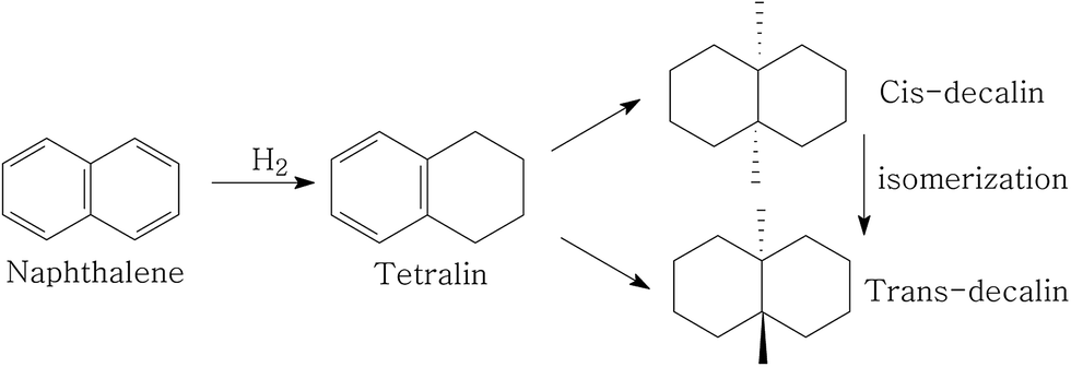 | ||
| Fig. 1 A schematic for naphthalene hydrogenation. | ||
The influence of individual P and USY promotion versus reaction temperature on the hydrogenation activity in naphthalene hydrogenation is presented in Fig. 2 and 3. Moreover, the hydrogenation activity of the ASA supported Ni catalyst prepared by saturated volume impregnation without the assistance of cis-9-octadecenylamine (Cat-IM) is included in the ESI (Fig. S1†). It can be observed that Cat-IM shows a lower hydrogenation activity than Cat. As listed in TEM (Fig. S2†) and H2-TPR (Fig. S3†), Cat displays better dispersion, smaller particle size and greater reducibility, and thus a higher hydrogenation activity than Cat-IM. As seen in Fig. 2, regardless of the reaction temperature, all P-doped catalysts exhibit higher hydrogenation activity than the P-free one. The conversion increases with increased loading of phosphorus and reaches the optimum at 1.0 wt% in the support. The increased hydrogenation activity on P addition indicates that P is in favor of naphthalene hydrogenation. Moreover, the USY-promoted catalysts show a different naphthalene hydrogenation activity trend upon reaction temperature. At 200 °C, the conversion still increases with increasing USY content. At 240 °C, Cat-10USY and Cat-20USY display the same hydrogenation activity, which is higher than Cat. It is interesting that the maximum value in conversion is observed over the catalyst decorated with 10 wt% USY at a reaction temperature of 280 °C. However, with the reaction temperature further increasing up to 320 °C, the USY-free catalyst shows higher hydrogenation activity than the one comprising 20 wt% USY and lower than the catalyst with 10 wt% USY. This may be because support by modification with 20 wt% USY brings more strong acid sites that accelerate coke formation, thus hindering the hydrogenation process.
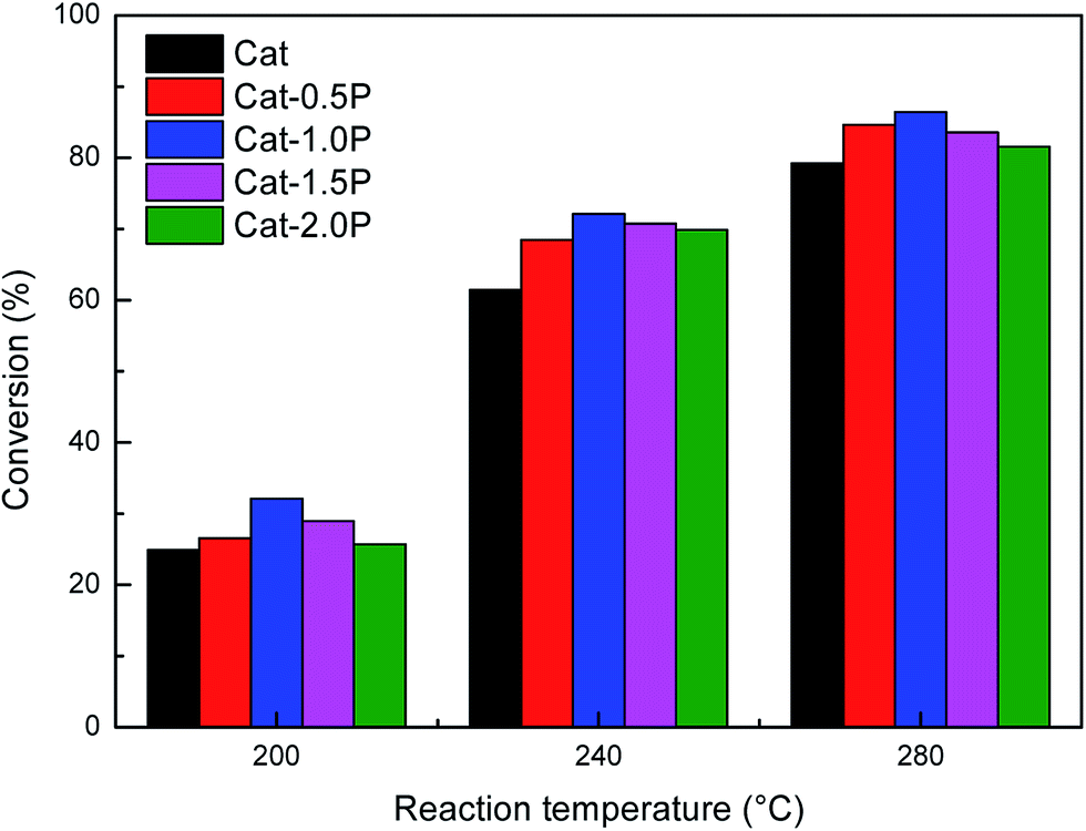 | ||
| Fig. 2 Effect of P content on the naphthalene hydrogenation activity at the reaction temperature of 200, 240 and 280 °C. Reaction conditions: P = 4 MPa, GHSV = 16 h−1, H2/oil = 600 (v/v). | ||
 | ||
| Fig. 3 Effect of USY content on the naphthalene hydrogenation activity at the reaction temperature of 200, 240, 280 and 320 °C. Reaction conditions: P = 4 MPa, GHSV = 16 h−1, H2/oil = 600 (v/v). | ||
Briefly, the support simultaneously modified with 1.0 wt% P and 10 wt% USY for Ni was prepared, and the catalyst was named as Cat-1.0P-10USY. Thus, the free-, individual P- and USY- as well as simultaneous P and USY modified catalysts were further studied in correlation with their physical–chemical properties and catalytic performance.
3.2. Characterization of the Cat, Cat-1.0P, Cat-10USY and Cat-1.0P-10USY catalysts
 | ||
| Fig. 4 X-ray powder diffractograms of the oxidic catalysts (a) and reductive catalysts (b). | ||
 | ||
| Fig. 5 TEM micrographs of the reductive catalysts: (a) Cat, (b) Cat-1.0P, (c) Cat-10USY, (d) Cat-1.0P-10USY. | ||
| Catalysts | SBETa (m2 g−1) | Vtotalb (m3 g−1) | Vmicro (m3 g−1) | Vmeso (m3 g−1) | dc (nm) | dNid (nm) |
|---|---|---|---|---|---|---|
| a Calculated by the BET method.b Calculated from the amounts of nitrogen adsorbed at P/P0 = 0.98.c Calculated by the BJH model.d Determined by TEM. | ||||||
| Cat | 375 | 0.987 | 0.158 | 0.829 | 10.52 | 9.8 |
| Cat-1.0P | 336 | 0.917 | 0.142 | 0.775 | 10.92 | 9.5 |
| Cat-10USY | 381 | 0.950 | 0.192 | 0.758 | 9.97 | 8.2 |
| Cat-1.0P-10USY | 358 | 0.939 | 0.167 | 0.772 | 10.22 | 6.0 |
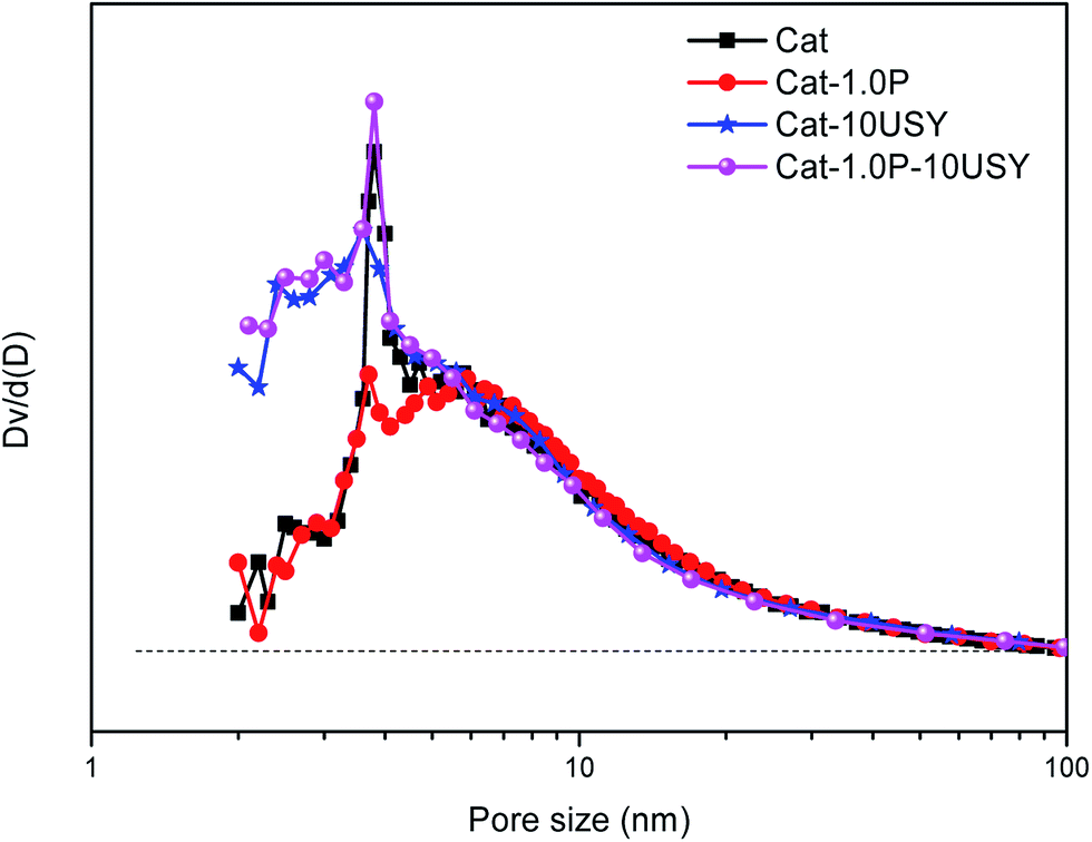 | ||
| Fig. 6 Pore size distributions of all catalysts. | ||
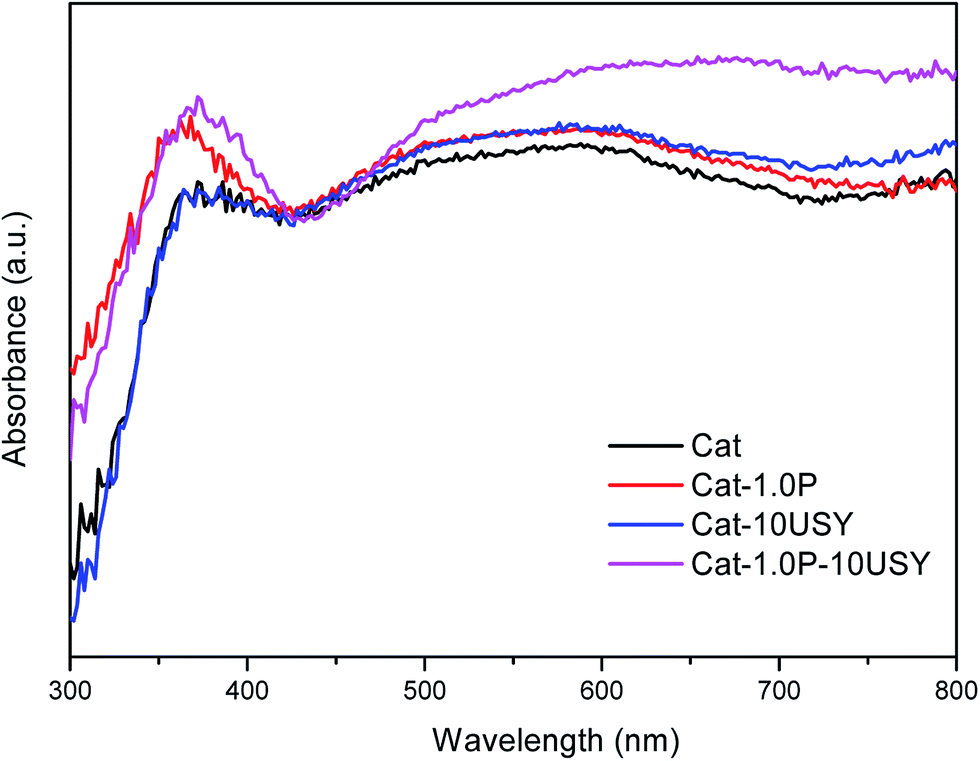 | ||
| Fig. 7 UV-vis DRS spectra of oxidic catalysts. | ||
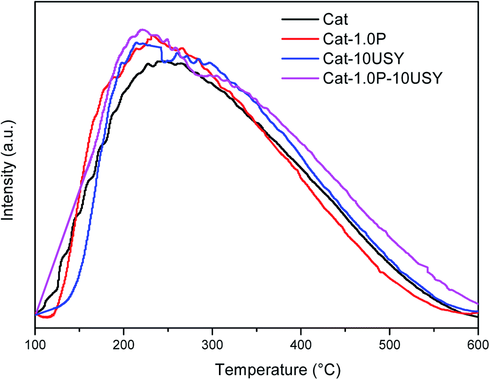 | ||
| Fig. 8 NH3-TPD of the catalysts. | ||
| Catalysts | Amount (μmol g−1) and distribution of acid sites | ||||||
|---|---|---|---|---|---|---|---|
| Total acid (μmol g−1) | Media and strong acid (μmol g−1) | Weak/total acid | |||||
| B | L | B + L | B | L | B + L | ||
| a B – Brønsted acid; L – Lewis acid. | |||||||
| Cat | 27 | 273 | 300 | 16 | 120 | 136 | 0.547 |
| Cat-1.0P | 36 | 295 | 331 | 21 | 126 | 147 | 0.556 |
| Cat-10USY | 52 | 283 | 335 | 30 | 140 | 170 | 0.492 |
| Cat-1.0P-10USY | 75 | 300 | 375 | 41 | 144 | 185 | 0.507 |
 | ||
| Fig. 9 H2-TPR profiles of all calcined catalysts. | ||
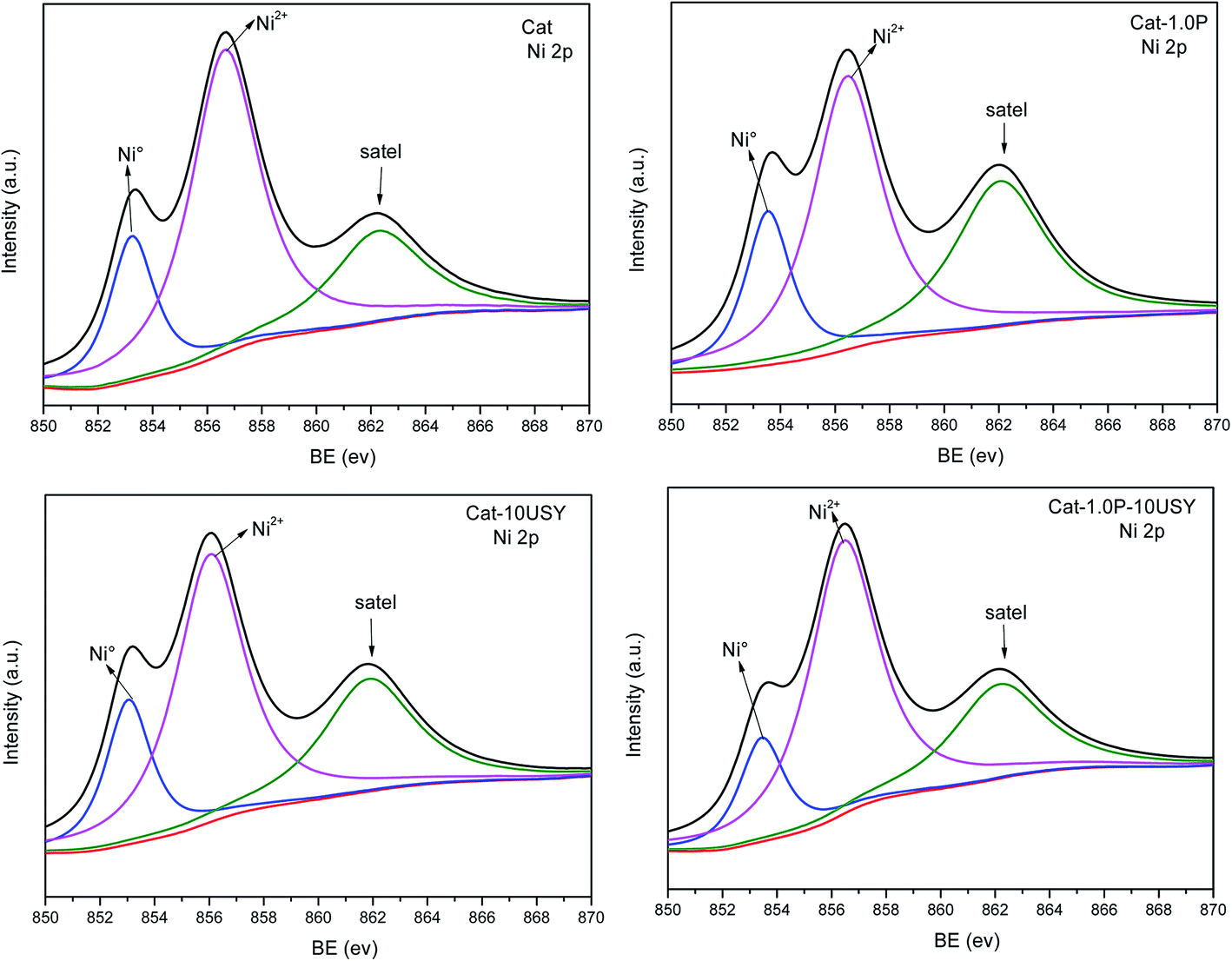 | ||
| Fig. 10 XPS Ni 2p2/3 spectra of the reductive catalysts. | ||
It is universally known that the surface exposure of metal is related to the metal–support interaction and metal dispersion as well as the metal particle size and has effects on the catalytic activity. The fitted results of the XPS spectra, including Si/Al, Nitotal/Al and Ni°/Al ratio, are listed in Table 3. As shown, derived from the Ni°/Al ratio, the surface exposure of the Ni° species in four catalysts follows the sequence: Cat-1.0P-10USY > Cat-10USY > Cat-1.0P > Cat. The USY modified catalysts of Cat-1.0P-10USY and Cat-10USY show evidently higher surface Ni° species than Cat and Cat-1.0P, which should be due to the former having smaller particle size, as evidenced in XRD and TEM results. Results of the higher exposure of Ni° in Cat-1.0P than in Cat are obtained, because the former has better dispersion of nickel species supported on the P modified catalyst compared to the P-free one, as proved by H2-TPR.
| Catalysts | Si/Al | Nitotal/Al | Ni°/Al |
|---|---|---|---|
| Cat | 0.479 | 0.0614 | 0.0149 |
| Cat-1.0P | 0.633 | 0.0642 | 0.0175 |
| Cat-10USY | 0.444 | 0.1014 | 0.0269 |
| Cat-1.0P-10USY | 0.464 | 0.1342 | 0.0272 |
3.3. Comparison of the hydrogenation activity over the Cat, Cat-1.0P, Cat-10USY and Cat-1.0P-10USY catalysts
The activities of four catalysts at 280 °C are presented in Fig. 11. As shown, Cat shows a conversion of 79.24% and a selectivity to decalin of 30.26%, which is lower than the other catalysts under the same conditions. Although Cat is provided with large specific surface area and pore volume as well as medium pore diameter, it performs poorly in the hydrogenation of naphthalene, which may be attributed to its low metal dispersion, surface exposure of Ni°, [NiOh2+]/[NiTd2+] ratio and acid amount. The catalyst modified with P alone displays not only a higher activity (86.45%) but also enhanced selectivity to decalin (42.4%) compared to the P-free one. This is clearly observed in Fig. 2. Combined with the characteristic results above, it is not difficult to speculate that the higher activity of Cat-1.0P is linked with the good dispersion of metal and its decreased interaction with the support as well as the high acid amount. As observed from Table 2, a larger amount of acid sites, particularly for Brønsted acid sites are formed on Cat-10USY. As Aguayo42 and Wang43 reported, Brønsted acid sites could promote the hydrogenation of aromatics. Combining XRD and TEM results, we observe that the nickel particles size over the USY modified catalyst is smaller, which could increase the surface area of the active sites. Therefore, the conversion and selectivity to decalin over Cat-10USY (84.66% and 40.36%) are enhanced with respect to Cat. The activity and selectivity of decalin over Cat-1.0P is slightly higher than Cat-10USY because the former has more NiOh2+ species, which will be transformed into the metal active sites, as shown in the UV-vis results. Due to the combination of P and USY, the catalyst simultaneously decorated with P and USY shows high acid amount, reducibility, and [NiOh2+]/[NiTd2+] ratio as well as good dispersion and small metal particle size. These factors prompt Cat-1.0P-10USY to exhibit superior hydrogenation activity and selectivity to decalin (90.38% and 50.38%).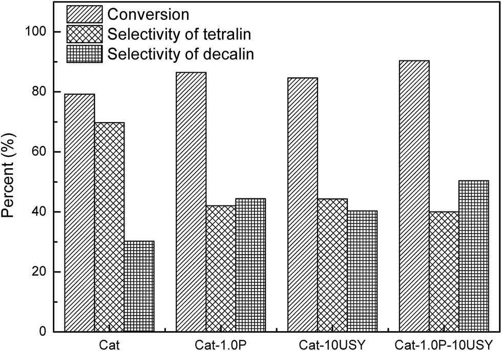 | ||
| Fig. 11 Hydrogenation of naphthalene over different catalysts. Reaction conditions: T = 280 °C, P = 4 MPa, GHSV = 16 h−1 and H2/oil = 600 (v/v). | ||
3.4. Comparison of the sulfur tolerance over the Cat, Cat-1.0P, Cat-10USY and Cat-1.0P-10USY catalysts
Other than the hydrogenation activity, the sulfur tolerance of the catalyst is also a pivotal evaluation criterion for the hydrotreating process in practical applications. In order to compare the sulfur tolerance of different catalysts, the feed containing 300 and 500 μg per g sulfur, using dibenzothiophene as the sulfur compound, was employed. The activities of naphthalene hydrogenation over Cat, Cat-1.0P, Cat-10USY and Cat-1.0P-10USY in the absence and presence of 300 and 500 μg per g sulfur, at a steady temperature of 280 °C, are summarized in Fig. 12. | ||
| Fig. 12 Comparison of hydrogenation activity of naphthalene in the absence and presence of DBT for all catalysts. 0 S represents the feed without sulfur, and 300 S and 500 S stands for the feed comprised of 300 μg per g sulfur and 500 μg per g sulfur. Reaction conditions: P = 4 MPa, T = 280 °C, GHSV = 16 h−1 and H2/oil = 600 (v/v). | ||
Regardless of the catalysts tested, when DBT was added to the reaction feed, a decrease in naphthalene hydrogenation activity was observed. The influence of sulfur content in the naphthalene hydrogenation process over four catalysts was assessed using 300 μg per g sulfur and 500 μg per g sulfur. As predicted, the hydrogenation activity and selectivity of decalin in the feed containing 500 μg per g sulfur is lower than that containing 300 μg per g sulfur. This is due to a competitive adsorption between DBT and naphthalene. Taking the higher content of sulfur (500 μg g−1 of S) for instance, Cat-1.0P-10USY has the highest activity, followed by the Cat-10USY, Cat-1.0P and Cat catalyst, and the conversion and selectivity of decalin decrease by 17.72% and 16.80%, 26.81% and 23.96%, 31.09% and 25.33% and 42.96% and 30.26%, respectively. The activity trend is different from the one in the absence of DBT (Cat-1.0P-10USY > Cat-1.0P > Cat-10USY > Cat). This strongly indicates a great difference in sulfur tolerance over various catalysts.
As listed in Fig. 12, all modified catalysts show higher sulfur tolerance than the one with no modification, which is due to improved physical–chemical properties over the former, such as acid amount, metal dispersion and pore structure. A substantial amount of research5,35,44–46 related to sulfur tolerance improvement through more acid sites has been reported. Furthermore, since the dispersion of active metal is enhanced, which corresponds to the increase of surface area of active phases, the capacity to contain poison is increased, and a similar phenomenon has been reported by Song.47 As discussed above, the P-containing catalyst owns a larger acid amount and better dispersion and thus, an improved sulfur tolerance. The catalyst of Cat-10USY shows a lower hydrogenation activity in the absence of DBT but a slightly higher activity in the presence of DBT compared to Cat-1.0P. As listed in Fig. 5 and Table 2, Cat-10USY has worse dispersion and a similar total acid amount as Cat-1.0P, but shows higher sulfur tolerance. This indicates that the prominent sulfur tolerance of the USY-containing catalyst is not only related to the total acid amount and metal dispersion but also more Brønsted acid sites and the hydrogen spillover effect. As various authors46,48,49 have reported, the resistance to sulfur increased with Brønsted acid sites. Moreover, in the USY modified catalyst, because of the coexistence of micropore and mesopore, the DBT could not access the Ni sites in the micropores. Hence, the active hydrogen would be formed on the sulfur free Ni sites and through the support bridge transferred to the nickel sites in the mesopores which are poisoned by sulfur. Then, the poisoned Ni sites would be partly recovered by hydrogen spillover, leading to an enhanced sulfur resistance. Accordingly, the greater improvement in sulfur tolerance due to the support simultaneously modified with P and USY is explained in terms of a multiple promotional effect of increased acid amount, particularly Brønsted acid amount, metal dispersion and hydrogen spillover.
4. Conclusions
The amorphous SiO2–Al2O3 (ASA) supported Ni catalysts was developed by support modification with individual and simultaneous incorporation of P and USY, and the catalysts were prepared using the hydrothermal synthesis method assisted by cis-9-octadecenylamine. The catalytic activities for naphthalene hydrogenation in the absence and presence of DBT were studied over free, individual and simultaneous P and USY promoted catalysts. All modified catalysts exhibited higher hydrogenation activity and selectivity of decalin than the freely P and USY decorated catalyst. When P was added to the ASA supported catalyst, the hydrogenation activities increased with the P content up to an optimum concentration of 1.0 wt%. When USY was introduced, an increased activity was obtained under the reaction temperature of 240–280 °C, which was particularly prominent at 10 wt% USY content. Moreover, the catalyst simultaneously promoted with 1.0 wt% P and 10 wt% USY exhibited superior hydrogenation activity, selectivity of decalin and sulfur tolerance, originating from the combination of the advantages of P and USY with ASA.References
- X. Chen, A. Zhao, Z. Shao, C. Li, C. T. Williams and C. Liang, J. Phys. Chem. C, 2010, 114, 16525–16533 CAS.
- M. Selvaraj, A. Selvamani, A. Alagarasi, M. Gurulakshmi, P. S. Krishnan, K. Suthagar and K. Shanthi, Sci. Adv. Mater., 2015, 7, 714–728 CrossRef CAS.
- B. H. Cooper and B. R. B. L. Donnis, Appl. Catal., A, 1996, 137, 203–223 CrossRef CAS.
- C. Song and X. Ma, Appl. Catal., B, 2003, 41, 207–238 CrossRef CAS.
- A. Stanislaus and B. H. Cooper, Catal. Rev.: Sci. Eng., 1994, 36, 75–123 CAS.
- T. Kan, X. Sun, H. Wang, C. Li and U. Muhammad, Energy Fuels, 2012, 26, 3604–3611 CrossRef CAS.
- A. Nishijima, T. Kameoka, T. Sato, N. Matsubayashi and Y. Nishimura, Catal. Today, 1998, 45, 261–269 CrossRef CAS.
- F. Luck, Bull. Soc. Chim. Belg., 1991, 100, 781–800 CrossRef CAS.
- X. Carrier, J. F. Lambert and M. Che, J. Am. Chem. Soc., 1997, 119, 10137–10146 CrossRef CAS.
- M. Breysse, P. Afanasiev, C. Geantet and M. Vrinat, Catal. Today, 2003, 86, 5–16 CrossRef CAS.
- A. Corma, M. T. Navarro and J. P. Pariente, J. Chem. Soc., Chem. Commun., 1994, 147–148 RSC.
- S. R. Kirumakki, B. G. Shpeizer, G. V. Sagar, K. V. R. Chary and A. Clearfield, J. Catal., 2006, 242, 319–331 CrossRef CAS.
- A. E. Coumans, D. G. Poduval, J. A. R. van Veen and E. J. M. Hensen, Appl. Catal., A, 2012, 411–412, 51–59 CrossRef CAS.
- A. Niquille-Röthlisberger and R. Prins, Ind. Eng. Chem. Res., 2007, 46, 4124–4133 CrossRef.
- A. Corma, V. González-Alfaro and A. V. Orchillés, J. Catal., 2001, 200, 34–44 CrossRef CAS.
- B. Pawelec, R. Mariscal, R. M. Navarro, S. van Bokhorst, S. Rojas and J. L. G. Fierro, Appl. Catal., A, 2002, 225, 223–237 CrossRef CAS.
- M. A. Arribas and A. Mart Nez, Appl. Catal., A, 2002, 230, 203–217 CrossRef CAS.
- Q. Meng, B. Liu, J. Piao and Q. Liu, J. Catal., 2012, 290, 55–64 CrossRef CAS.
- Y. Yin, L. Qin, X. Wang, G. Wang, J. Zhao, B. Liu and Y. Chen, RSC Adv., 2016, 6, 111291–111298 RSC.
- M. Du, Z. Qin, H. Ge, X. Li, Z. Lü and J. Wang, Fuel Process. Technol., 2010, 91, 1655–1661 CrossRef CAS.
- P. Atanasova, T. Tabakova, C. Vladov, T. Halachev and A. L. Agudo, Appl. Catal., A, 1997, 161, 105–119 CrossRef CAS.
- S. K. Maity, J. Ancheyta, M. S. Rana and P. Rayo, Catal. Today, 2005, 109, 42–48 CrossRef CAS.
- J. M. Herrera, J. Reyes, P. Roquero and T. Klimova, Microporous Mesoporous Mater., 2005, 83, 283–291 CrossRef CAS.
- R. Huirache-Acuña, B. Pawelec, E. Rivera-Muñoz, R. Nava, J. Espino and J. L. G. Fierro, Appl. Catal., B, 2009, 92, 168–184 CrossRef.
- J. L. G. Fierro, A. L. Agudo, N. Esquivel and R. Lopez Cordero, Appl. Catal., 1989, 48, 353–363 CrossRef CAS.
- S. Sigurdson, V. Sundaramurthy, A. K. Dalai and J. Adjaye, J. Mol. Catal. A: Chem., 2008, 291, 30–37 CrossRef CAS.
- R. Lopez Cordero, S. Lopez Guerra, J. L. G. Fierro and A. Lopez Agudo, J. Catal., 1990, 126, 8–12 CrossRef CAS.
- R. Nava, A. Infantes-Molina, P. Castaño, R. Guil-López and B. Pawelec, Fuel, 2011, 90, 2726–2737 CrossRef CAS.
- M. A. Guzmán, R. Huirache-Acuña, C. V. Loricera, J. R. Hernández, J. N. Díaz De León, J. A. de Los Reyes and B. Pawelec, Fuel, 2013, 103, 321–333 CrossRef.
- D. Nicosia and R. Prins, J. Catal., 2005, 229, 424–438 CrossRef CAS.
- P. Li, C. Nan, Z. Wei, J. Lu, Q. Peng and Y. Li, Chem. Mater., 2010, 22, 4232–4236 CrossRef CAS.
- C. Shen, C. Hui, T. Yang, C. Xiao, J. Tian, L. Bao, S. Chen, H. Ding and H. Gao, Chem. Mater., 2008, 20, 6939–6944 CrossRef CAS.
- R. Chiang and R. Chiang, Inorg. Chem., 2007, 46, 369–371 CrossRef CAS PubMed.
- X. Zheng, S. Yuan, Z. Tian, S. Yin, J. He, K. Liu and L. Liu, Mater. Lett., 2009, 63, 2283–2285 CrossRef CAS.
- A. Corma, A. Martinez and V. Martinez-Soria, J. Catal., 1997, 169, 480–489 CrossRef CAS.
- T. He, Y. Wang, P. Miao, J. Li, J. Wu and Y. Fang, Fuel, 2013, 106, 365–371 CrossRef CAS.
- A. Morales, M. M. Ramirez De Agudelo and F. Hernandez, Appl. Catal., A, 1988, 41, 261–271 CrossRef CAS.
- M. Schiavello, M. L. Jacono and A. Cimino, J. Phys. Chem., 1971, 75, 1051–1057 CrossRef.
- C. A. Emeis, J. Catal., 1993, 141, 347–354 CrossRef CAS.
- J. Zhao, Y. Yin, Y. Li, W. Chen and B. Liu, Chem. Eng. J., 2016, 284, 405–411 CrossRef CAS.
- P. Castano, B. Pawelec, J. L. G. Fierro, J. M. Arandes and J. Bilbao, Fuel, 2007, 86, 2262–2274 CrossRef CAS.
- A. T. Aguayo, A. G. Gayubo, R. Vivanco, M. Olazar and J. Bilbao, Appl. Catal., A, 2005, 283, 197–207 CrossRef CAS.
- J. Wang, Q. Li and J. Yao, Appl. Catal., A, 1999, 184, 181–188 CrossRef CAS.
- C. Song and A. D. Schmitz, Energy Fuels, 1997, 11, 658–661 CrossRef.
- H. Yasuda, N. Matsubayashi, T. Sato and Y. Yoshimura, Catal. Lett., 1998, 54, 23–27 CrossRef CAS.
- W. M. H. Sachtler and A. Y. Stakheev, Catal. Today, 1992, 12, 283–295 CrossRef CAS.
- H. J. Kim and C. Song, Energy Fuels, 2014, 28, 6788–6792 CrossRef CAS.
- M. Jian and R. Prins, J. Catal., 1997, 179, 18–27 CrossRef.
- L. J. Simon, M. Rep, J. G. van Ommen and J. A. Lercher, Appl. Catal., A, 2001, 218, 161–170 CrossRef CAS.
Footnote |
| † Electronic supplementary information (ESI) available. See DOI: 10.1039/c7ra05413k |
| This journal is © The Royal Society of Chemistry 2017 |