
 Open Access Article
 This Open Access Article is licensed under a Creative Commons Attribution-Non Commercial 3.0 Unported Licence
Synthesis of uniform rare earth doped Gd2O2S sub-micron sized spheres using gas-aided sulfurization and their optical characteristics†
Shuqing He‡
,
Xinyu Zhao‡ and
Mei Chee Tan*
and
Mei Chee Tan*
Engineering Product Development, Singapore University of Technology and Design, 8 Somapah Road, Singapore 487372. E-mail: meichee.tan@sutd.edu.sg
First published on 19th July 2017
Abstract
In this work, we report a detailed study of the synthesis of sub-micron sized Gd2O2S spheres using a two-step process: (1) amorphous precursor synthesis using the solvothermal method where a surfactant was used to control particle morphology, followed by (2) crystallization to form Gd2O2S polycrystalline spheres in a sulfur-rich environment. The crystallization and sulfurization processes are investigated by monitoring the crystal growth at different temperatures and under different environments using mainly X-ray diffraction and analysis of the precursor's thermal decomposition profile. The optical emissions of the Er and Yb-Er doped Gd2O2S upon excitation at 975 nm were investigated to identify the optimal dopant concentrations, optimal heat treatment temperature as well as to further elucidate any fine structure changes. Our results also show that the maximum emission intensities were obtained for a heat treatment temperature of 800 °C, where increased dopant diffusion coupled with non-uniform surface segregation at much higher temperatures led to non-uniform dopant distribution and reduced emission intensities. Our findings from these studies would be useful towards the synthesis of brightly-emitting Gd2O2S based luminescent materials as well as for the controlled gas-aided sulfurization of other metal oxysulfides.
1. Introduction
Luminescent powders that utilize rare earth dopants as a means to engineer atomic-like optical emission characteristics offer a diverse range of profiles because of the vast energy level transitions offered by the different rare-earth elements available and the ability to dope with more than one rare-earth species.1,2 The optical characteristics are mainly tailored by controlling the local atomic environment and electron–phonon interaction strength of the rare earth dopants, where halide and chalcogenide hosts are favored for their low phonon energies (∼300–600 cm−1) which minimize non-radiative losses to enable intense emissions over the visible and infrared regions.1 Rare earth doped particles have also received much attention because they exhibit both the down-shifting (i.e. Stokes shift) and upconversion (i.e. anti-Stokes) phenomena that have been exploited for fluorescence biomedical imaging.3 In another aspect, the unique upconversion property has also been harnessed to increase the absorption range of silicon-based solar cells to enhance its photon conversion efficiency.4–7 By enabling the absorption of sub-band gap photons via the upconversion process, it is anticipated that the maximum theoretical efficiency can be increased from ∼33 to ∼40% for crystalline silicon-based solar cells.6,7One of the leading hosts that have been identified to enable more efficient emissions are the rare earth oxysulfides (Ln2O2S; Ln = La, Gd, Y).6,7 Gadolinium oxysulfide was recently reported to yield much higher upconversion efficiencies compared to the existing benchmark that was set using NaYF4. The reported internal infrared to near-infrared upconversion quantum yield of Gd2O2S:Er10 (i.e., 12 ± 1% for 10 mol% Er) is ∼30% higher than that of NaYF4:Er25 (i.e., 8.9 ± 0.7% for 25 mol% Er) at the same irradiance using a monochromatic excitation of 1510 nm at a power of 700 W m−2.6,7 Since the reported maximum effective phonon energy of Gd2O2S at ∼505 cm−1 is comparable to that of ∼440 cm−1 for β-NaYF4, the multiphonon relaxation rates for systems should be identical, leading to identical relaxation losses.8,9 However, unlike β-NaYF4 which provides two sites for the rare earth host ions and dopants (e.g., Gd3+, Yb3+, Er3+), Gd2O2S has only one well defined site. The multi-site occupancy of the rare earth emitting centers leads to additional atomic-level disorders leading to broader emission profiles for the rare earth doped β-NaYF4 system. Consequently, the improved upconversion efficiency may be attributed partly to the narrower excitation and emission profiles of Gd2O2S, where reabsorption losses are reduced and the absorbed energy is directed to fewer emission channels due to the smaller extent of overlap between excitation and emission bands (see Fig. S1†). In addition to its fluorescence properties, Gd-based material systems are also well established as T1 contrast agents for magnetic resonance imaging (MRI),10 whilst Gd2O2S has been evaluated as scintillator-based X-ray detectors.11 Therefore, in addition to fluorescence imaging, additional opportunities are uncovered for the use of these Gd-based hosts as a contrast agents supporting multiple imaging modalities such as T1-MRI and X-ray computed tomography imaging. Furthermore, these oxysulfide hosts also possess favorable chemical durability, and are likely to be less toxic compared to the halide counterparts.12
The many diverse potential applications for the rare earth doped Gd2O2S systems have fueled various efforts towards the synthesis of Gd2O2S particles with a uniform size and morphology.13–15 The existing methods rely heavily on the solid state reaction routes, where the sulfurization of rare-earth oxides is achieved using sulfur sources such as vaporized sulfur, hydrogen sulfide or carbon disulfide at elevated temperatures ranging from 500–1100 °C.6 Based on the thermodynamic phase diagrams,14,16 the small stable region of Gd2O2S compared with Gd2O3 and Gd2S3 indicates that the processing environment needed to obtain pure phase Gd2O2S is highly constrained. This narrow window of stability is partly due to the lack of affinity between the hard Lewis acid Ln3+ and the soft Lewis base S2−, as predicted by the theory of hard and soft acids and bases.14,15,17 In addition, powders prepared using the solid state reaction method have high surface defect densities which are an inevitable consequence of the grinding of powders that is needed after reaction. These surface defects would act as non-radiative recombination centers leading to increased non-radiative relaxation and reduced radiative emission intensities. Furthermore, these powders are generally in the micron-sized (e.g., ∼2 to 10 μm) with irregular and uncontrolled morphologies.6 Such large particle sizes will not meet the design requirements (i.e., required sizes < 200 nm) for most biomedical and optical device applications.1,2 For example, large particle sizes generally result in significant light scattering losses and are unsuited for low-loss optical device applications.1,2
Consequently, recent efforts have been channeled towards the design and synthesis of lanthanide oxysulfides at a smaller scale (e.g., sub-micron and nanoscale) with uniform particle morphology using the solvothermal approach.15,17,18 The solvothermal synthesis method operates in a chemically uniform environment such that particles with high chemical and phase purity are synthesized.1,2 Various examples of a range of rare-earth doped materials of different controlled sizes and morphologies have been grown by controlling the chemical reaction variables, like time, precursor concentration, surfactants and solvent. In this work, we conducted a detailed study of the synthesis of Gd2O2S spheres with sub-micron dimensions using a two-step process that was adapted from a previous work.13 In the first step, an intermediate amorphous precursor phase is prepared using the solvothermal method. This is followed by the crystallization of the amorphous precursors to form Gd2O2S crystalline particles using a gas-aided sulfurization process at elevated temperatures. The advantages of two-step synthesis method lie in the better control of: (1) the product morphology and composition via using surfactants during solvothermal synthesis, and (2) the extent of sulfurization to obtain phase pure Gd2O2S as opposed to the much more stable Gd2S3 or Gd2O3. The crystallization and sulfurization processes are studied by monitoring the crystal growth (crystal phase and grain size) at different temperatures and environments. In addition, the optical characteristics (i.e., visible and infrared emissions) of the Er and Yb-Er doped Gd2O2S are investigated to identify the optimum dopant concentrations and photon energy transfer pathways as well as to further elucidate any fine structure changes. The findings from our studies would be useful towards developing strategies towards controlled gas-aided sulfurization of lanthanide (Ln) oxysulfides and the synthesis of brightly-emitting Gd2O2S based luminescent materials.
2. Experimental methods
2.1 Precursor powder preparation
All chemicals were purchased from Sigma-Aldrich (SigmaAldrich, St. Louis, MO) and used as received without any further purification. The precursors were first synthesized using the solvothermal method.13 In a typical precursor synthesis procedure for Gd2O2S:Yb8Ers (i.e., 8 mol% Yb and 1 mol% Er), 1.82 mL of 1 M GdCl3·6H2O (i.e., 1.82 mmol Gd), 0.32 mL of 0.5 M Yb(NO3)3·5H2O (i.e., 0.16 mmol), 0.04 mL of 0.5 M Er(NO3)3·5H2O (i.e., 0.02 mmol), and 2.82 mL deionized water were mixed with 25 mL of ethylene glycol (EG). This was followed by the addition of 2.0 g (i.e., 0.05 mmol) of poly(vinylpyrrolidone) (PVP, 40![[thin space (1/6-em)]](https://www.rsc.org/images/entities/char_2009.gif) 000 g mol−1). PVP was completely dissolved after vigorous stirring of the solution for ∼10 min using a magnetic stir plate. Next, ∼10 mL of ethanol solution containing 0.11 g of thiourea (Tu, ∼1.45 mmol) was added dropwise into the above solution. The final solution was stirred for another ∼30 min until it became transparent and clear, before being transferred to a 125 mL Teflon liner. The measured pH of this solution was ∼3.75, where metal hydroxide precipitation is not likely. Subsequently, the Teflon liner was placed within a stainless-steel Parr digestion vessel and heated at 200 °C for 24 h. At the end of the reaction, the precipitates were separated by filtration and washed using a mixture of ethanol and deionized water for five times before being dried at 60 °C overnight in a convection oven. Powder doped other concentrations of Yb and Er were prepared by changing the corresponding amounts of GdCl3, Yb(NO3)3 and Er(NO3)3 whilst all other parameters were kept constant.
000 g mol−1). PVP was completely dissolved after vigorous stirring of the solution for ∼10 min using a magnetic stir plate. Next, ∼10 mL of ethanol solution containing 0.11 g of thiourea (Tu, ∼1.45 mmol) was added dropwise into the above solution. The final solution was stirred for another ∼30 min until it became transparent and clear, before being transferred to a 125 mL Teflon liner. The measured pH of this solution was ∼3.75, where metal hydroxide precipitation is not likely. Subsequently, the Teflon liner was placed within a stainless-steel Parr digestion vessel and heated at 200 °C for 24 h. At the end of the reaction, the precipitates were separated by filtration and washed using a mixture of ethanol and deionized water for five times before being dried at 60 °C overnight in a convection oven. Powder doped other concentrations of Yb and Er were prepared by changing the corresponding amounts of GdCl3, Yb(NO3)3 and Er(NO3)3 whilst all other parameters were kept constant.
2.2 Heat treatment in sulfur-rich environment to obtain Gd2O2S particles
The dried precursor powder (∼50 mg) was finely ground using an agate mortar and pestle prior to heat treatment using a tube furnace (Type STF 16/180, Carbolite Ltd. Germany). 500 mg of sulfur (i.e., boiling point ∼445 °C) in two rectangular alumina crucibles (30 mL) was introduced and positioned to sandwich the sample to create a sulfur-rich atmosphere in the tube furnace. The precursor powders were next heated in a rectangular alumina crucible (30 mL) from ambient conditions to a desired temperature for 2 h, using a heating rate of 10 °C min−1 with an argon flow rate of 60 mL min−1.2.3 Material characterization
 | (1) |
3. Results and discussion
3.1 Synthesis and characterization of the intermediate precursor powders
In our method, the intermediate precursor powders are prepared using a solvothermal reaction, where a homogenous solution comprising of rare earth salts at the desired stoichiometric ratios, PVP and thiourea (Tu) are dissolved in a mixed solvent of water and ethylene glycol. In this reaction, the weak base Tu would serve mainly as the sulfur source, whilst PVP would act as the oxygen source and surfactant that controls the morphology of the as-prepared precursor powders. Compared to most methods that limit the sulfurization to only during the heat treatment process by using sulfur sources such as, hydrogen sulfide or carbon disulfide, we have controlled the extent of sulfurization by introducing sulfur in both the intermediate precursor as well as during the heat treatment process. The introduction of sulfur in both steps could potentially lead to lower Gd2O2S crystallization temperatures which consequently limits interparticle sintering leading to improved control over the particle morphology and size distribution. In this case, Tu is one of the few chemicals that is soluble in aqueous media and also able to coordinate with the rare earth metal ions to form an amorphous intermediate of sulfur-containing precursors by precipitation during hydrothermal synthesis. A proposed scheme that describes the homogenous precipitation of our precursors via the hydrolysis of Tu during the solvothermal reaction is shown in Scheme 1.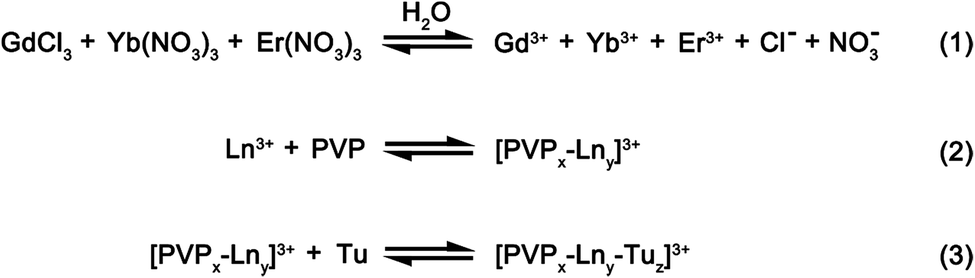 | ||
Scheme 1 Schematic representing the key steps for the formation of the precursors. The steps include: (i) hydrolysis of rare earth salts (Ln3+) in aqueous solution, (ii) formation of [PVPx–Lny]3+ complex through the interactions between the metal ion and the carbonyl (i.e. C![[double bond, length as m-dash]](https://www.rsc.org/images/entities/char_e001.gif) O) group on PVP and (iii) [PVPx–Lny–Tuz]3+ formation through coordination of [PVPx–Lny]3+ complexes with the free Tu molecules. O) group on PVP and (iii) [PVPx–Lny–Tuz]3+ formation through coordination of [PVPx–Lny]3+ complexes with the free Tu molecules. | ||
In our proposed scheme, the rare earth salts (e.g., GdCl3, Yb(NO3)3, Er(NO3)3) would first dissociate in water to form free metal ions. With the addition of water soluble PVP, these free metal ions would form a complex with PVP through its interactions between the metal ion and the carbonyl (i.e. CO) group on PVP.20 With the subsequent addition of Tu, these [PVPx–Lny]3+ complexes could also form coordination complexes with the free Tu molecules.21 The stoichiometric ratio of PVP and Tu with the central rare earth ion (i.e., [PVPx–Lny–Tuz]3+) in the primary coordinating sphere would depend on the relative binding affinity of the rare earth ion with the ligand and the relative ligand amounts that are being added. Since the amount of Tu (∼1.45 mmol) is ∼30 times more than PVP (∼0.05 mmol) added, we would expect Tu to be the dominant ligand surrounding the rare earth metal ion, Ln3+ in the primary coordinating sphere. Whilst Tu is being hydrolyzed to initiate homogenous precipitation of an intermediate phase during the solvothermal reaction at 200 °C, PVP serves as a particle stabilizer and dictates the morphology of the as-synthesized intermediate precursor phase.22 In our synthesis, PVP controls the particle growth process by physically adsorbing on the nuclei surfaces which result in the formation of highly uniform spheres (see Scheme 2).18,23
 | ||
| Scheme 2 Schematic representation of the heat treatment and crystallization of micron-sized polycrystalline Gd2O2S particles. The precursors formed after solvothermal synthesis are coated with a layer of PVP. In addition to controlling the particle morphology, the PVP coating would most likely serve as a sintering inhibitor that prevented interparticle fusion. The rare earth doped Gd2O2S formation process includes: (i) decomposition the precursors during heat treatment in a sulfur-rich environment, followed by (ii) the crystallization by ∼600 °C and grain growth of phase pure Gd2O2S particles at higher temperatures. | ||
The physiochemical characteristics of the as-prepared intermediate precursor powders were characterized using the scanning electron microscope (SEM), X-ray diffraction (XRD) and Fourier Transform Infrared (FTIR) spectroscopy (see Fig. 1). The SEM image shows that 122.2 ± 15.9 nm precursor powders with a uniform spherical morphology were prepared (see Fig. 1(a)). From the XRD powder measurements, a broad 2θ peak from 20° to 35° (grain size of ∼1 nm) was observed (see Fig. 1(b)). Therefore, the XRD profile of our precursor powders indicated that an amorphous phase was formed after solvothermal synthesis. Due to the amorphous nature, we were not able to deduce the likely chemical structure of our precursors from the XRD results. Therefore, the infrared spectra were used to characterize these as-prepared precursors (see Fig. 1(c) and (d)). The principal peaks from the FTIR spectra were assigned to the vibrational modes of the chemical groups in our precursors, Tu and PVP as shown in Table 1.20,24 By comparing the FTIR spectra of pure Tu and PVP, unique signatures were identified (see Table 1). For example, the principal C–H (i.e., 2949 and 2875 cm−1) and CO (i.e., ∼1651 cm−1) peaks are signature of PVP and absent in Tu.20 These signature PVP peaks are barely present in the spectrum of our as-prepared precursor powders (see Fig. 1(c)), where only a weak shoulder at ∼1651 cm−1 associated with CO was identified. In contrast, several bands unique only to Tu were observed. For example, the bands of C–N (i.e., 1460 to 1510 cm−1) and CS (i.e., 1400 to 1420 cm−1) were clearly observed (see Table 1).24
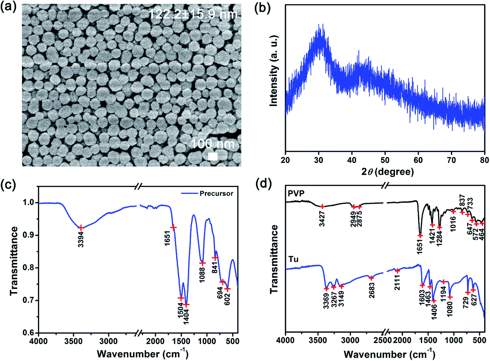 | ||
| Fig. 1 Physiochemical characteristics of precursors using the solvothermal method. (a) SEM images show uniform sub-microspheres with a narrow size distribution, (b) XRD profiles of the as-synthesized precursors show a broad peak that characterizes amorphous materials, FTIR spectra of the (c) as-synthesized precursors as well as (d) polyvinylpyrrolidone (PVP) and thiourea (Tu) suggested that precursors of PVP-coated [Lny–Tuz]3+ were formed. | ||
| PVP | Tu | Precursor | |||
|---|---|---|---|---|---|
| Wavenumber (cm−1) | Assignment | Wavenumber (cm−1) | Assignment | Wavenumber (cm−1) | Assignment |
| 3427 (broad) | νas,s(HOH) | ||||
| 3369 (st.) | νas(NH2) | 3394 | νas,s(NH2) or νas,s(HOH) | ||
| 3267 (st.) | νas(NH2) | ||||
| 3149 (st.) | νs(NH2) | ||||
| 2949 (st.) | νas(CH2) | ||||
| 2875 (st.) | νs(CH2) | ||||
| 2683 (wk) | νas(NH2), δ(N–C–S) | ||||
| 2111 (wk) | (NH2) rocking | ||||
| 1651 (st.) | νs(CO) |
1651 | νs(CO) |
||
| 1603 (med.) | δ(NH2) | ||||
| 1504 | νas(N–C–N) or νas(C–N) | ||||
| 1463 (med.) | νas(C–N) | ||||
| 1421 (st.) | ν(C–N) | 1406 (med.) | νas(C–S) | 1404 | νas(C–S) |
| 1284 (st.) | δ(C–H) | ||||
| 1080 (med.) | νs(C–N) | 1088 | νs(C–N) | ||
| 1016 (wk) | (C–C) breathing | ||||
| 837 (wk) | 850 (wk) | δw(NH2) | 841 | δw(NH2) | |
| 733 (wk) | C–C chain | 729 (med.) | νs(C–S) | 694 | νs(C–S) |
| 647 (wk) | N–C + O bond | 627 (med.) | δas(N–C–S) | 602 | δas(N–C–S) |
Besides identifying the signature chemical functional groups on our precursors, additional aspects on the rare earth bonding characteristics could be inferred from on our FTIR data. First, the absence of the CH2 bands suggests that the ligand surrounding the metal is mostly Tu rather than PVP such that the metal complex is most likely [Lny–Tuz]3+. This is consistent with our earlier discussion where we expected the coordinating ligand in the primary sphere to be mostly Tu due to its large excess. Next, the coordination between Ln and Tu is evaluated based on the simultaneous changes in the C–N and CS peak positions and intensities. The Ln–Tu coordination may occur either through the Ln3+ bonding to the nitrogen or through sulfur of Tu. Our results show that the CS associated peaks generally shifted toward lower wavenumbers, where the stretching and vibration bands were shifted from 1406 to 1404 cm−1 and 729 to 694 cm−1, respectively. In contrast the C–N stretching bands were shifted to higher wavenumbers from 1463 to 1504 cm−1, and from 1080 to 1088 cm−1. These changes to CS and C–N suggest that the formation of a metal sulfur bond was most likely (see Fig. S2†). When CS is bonded to Ln3+, the CS stretching of Tu would shift to a lower value than that of pure Tu.24 The lowering of the wavenumber was attributed to formation of S–Ln3+ bonds which increases the polarity of Tu leading to a greater single bond character and weakening of the carbon to sulfur bond. This will also result in a greater double bond character and strengthening of the nitrogen to carbon bond which give rises to shift of C–N bands to higher wavenumbers. Therefore, the observed shifting of the N–C–S band from 627 to 602 cm−1 was also attributed to the formation of the S–Ln3+ coordinate bond that led to the N–C–S bond delocalization and resultant shift to lower energies. The weak shoulder peak at ∼1651 cm−1 suggests that the available PVP was present at very low amounts. Considering the low surface area per volume of our sub-micron sized particles and the FTIR results, this suggests that PVP is most likely coated around the precursors (see Scheme 2).
3.2 Gd2O2S crystallization via controlled heat treatment
These amorphous intermediate precursor powders are next crystallized to form Gd2O2S crystalline particles using a heat treatment process in a sulfur-rich environment. By decoupling the synthesis into separate steps, we aim to achieve better control of the powder morphology and the sulfurization extent so as to obtain pure phase Gd2O2S (see Scheme 2). A key step that dictates the formation of Gd2O2S is the thermally driven decomposition of the intermediate precursor powders that were prepared using the solvothermal reaction. The decomposition of the precursor powders was evaluated by measuring the sample weight loss and change in heat flow as temperature increases from ambient conditions to 1200 °C using the TGA and differential thermal analyzer (DTA), respectively (see Fig. 2 and S3†). The first derivative of the TGA results were used to identify the points of inflection which will also mark the regions where major weight loss events were observed (see Fig. S3†). After identifying these segments, we tabulated the measured weight loss that corresponded with these regions (see Table 2). The initial weight loss of ∼6% for region I is most likely due to the vaporization of residual solvents (e.g., water, ethanol) that are trapped within the powders. The second major weight loss of ∼8% was attributed to corresponding decomposition of Tu, where pure Tu is reported to decompose from ∼220 °C (onset, see Fig. S3†).25 The higher than expected Tu decomposition temperature (i.e., inflection point at 369 °C, onset at ∼200 °C) was most likely due to the additional energy required to break the strong S–Ln3+ coordination bond that we have discussed in the earlier section. The typical gaseous products formed by the decomposition of Tu are ammonia (NH3), isothiocyanic acid (HNCS) and carbon disulfide (CS2).25 The third region with the highest weight loss of 10% was attributed to the decomposition of PVP in nitrogen, since pure PVP has been reported to dissociate at ∼380 °C (inflection point).26 The slightly higher dissociation temperature of PVP (i.e., inflection point at 436 °C, onset at ∼400 °C) compared to pure PVP was most likely associated with the additional interactions between PVP with the precursor powders. Two additional regions at much higher temperatures of 600–700 °C and 800–1200 °C with weight losses of ∼3% and ∼6%, respectively, were observed. These weight losses were attributed to the pyrolysis of residual carbon or other organic constituents formed as the byproducts of PVP or Tu decomposition.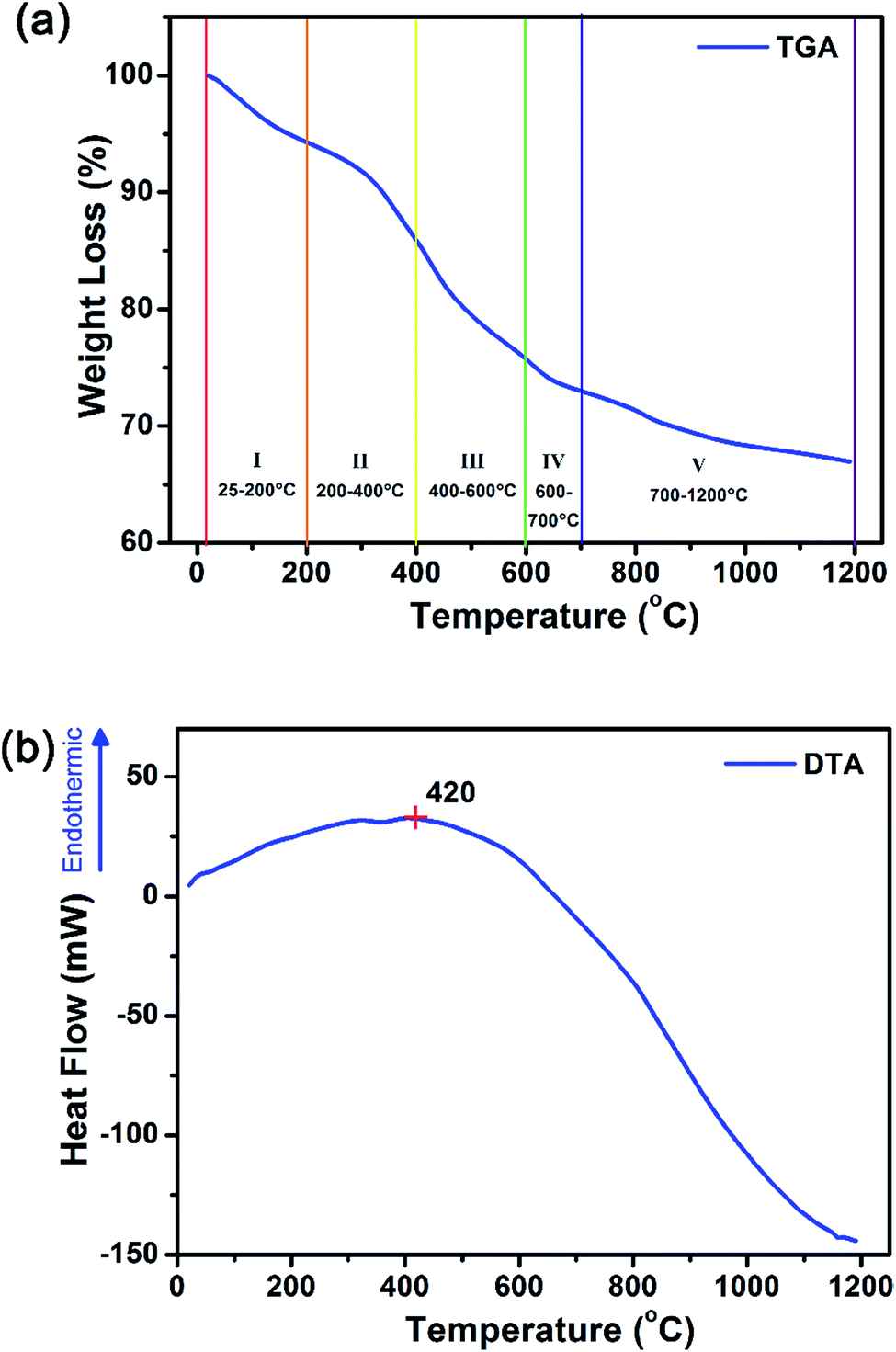 | ||
| Fig. 2 Simultaneous thermal analysis of the precursor decomposition in inert nitrogen environment shows that there were five transition weight loss transition regions from (a) weight loss profile of the TGA measurements in nitrogen. In addition, precursor decomposition (i.e. bond breaking, endothermic) processes dominated at <420 °C and crystallization (i.e. bond formation, exothermic) starts from >420 °C from the (b) changes in heat flow based on DTA measurements. | ||
| Region | Temperature range (°C) | Weight loss (%) |
|---|---|---|
| I | 25–200 | 6.0 |
| II | 200–400 | 8.0 |
| III | 400–600 | 10.0 |
| IV | 600–700 | 2.7 |
| V | 700–1200 | 6.0 |
Considering the temperature and weight losses in both regions, there were most likely two types of residual carbon: (1) carbon coating around the precursors formed as a result of PVP decomposition, and (2) carbon located within the intergrain boundaries as a result of Tu decomposition. Much more energy would be required to burn off the residual carbon located at the intergrain boundaries compared to that surrounding external carbon coating since more bonds would have to be broken. Therefore, it is most likely that the weight loss in the 600–700 °C range is associated to residual carbon coating, whilst the weight loss at the higher temperatures is from the subsequent removal of residual carbon at the intergrain boundaries. The DTA results show an increase in heat flow from ambient conditions up to ∼420 °C before it starts to decrease with the increase in temperature to 1200 °C. The increase in heat flow indicates that the sample is undergoing an endothermic process which is often related to the energy required to break bonds (e.g., during melting, vaporization and decomposition of molecules). This is consistent with our TGA analysis, where organic vaporization and Tu decomposition processes dominated below ∼420 °C. The subsequent decrease in heat flow suggests the increase dominance of exothermic processes which is related to the energy released during bond formation (e.g., during crystallization).
To investigate the powder crystallization process during heat treatment, XRD profiles of these precursor powders from 500 to 1200 °C in a static vacuum environment or sulfur-rich environment using inert argon as a carrier gas were collected (see Fig. 3 and S4†). In order to crystalize the amorphous precursors, additional energy to overcome the activation barrier energy needed of the reaction. Fig. 3(a) shows that the amorphous-to-crystalline phase transition temperature in vacuum was ∼675 °C (see Fig. S3† for data from 600–700 °C). In a vacuum environment, crystalline Gd2O3 was formed above the phase transition temperature, suggesting that sulfur content within the precursors [Lny–Tuz]3+ was insufficient to form the desired Gd2O2S phase, and the oxygen released from the thermal decomposition of PVP was sufficient for the formation of Gd2O3. The crystalline grain size estimated using the Scherrer's equation indicated that the grain sizes increased from ∼3 to ∼35 nm as temperature increases to ∼1100 °C (see Fig. 3(b)). In addition, we observed 2 grain growth zones with distinctly different kinetics: (1) rapid size increase from 3 to 12 nm for 675–800 °C (steep gradient), and (2) a more gradual increase from ∼12 to 35 nm for 800–1100 °C (see Fig. 3(b)). The two separate grain growth zones were attributed to the removal of residual carbon or other minor organic constituents formed by the decomposition of either PVP and Tu, which is consistent with our earlier TGA results (see Fig. 2(a) and Table 2). The removal of residual carbon facilitates grain growth by eliminating the diffusive barrier that limited grain boundary diffusion. It should be noted that residual carbon has to be removed sequentially first from the external carbon coating followed by the residual carbon located at the intergrain boundaries.
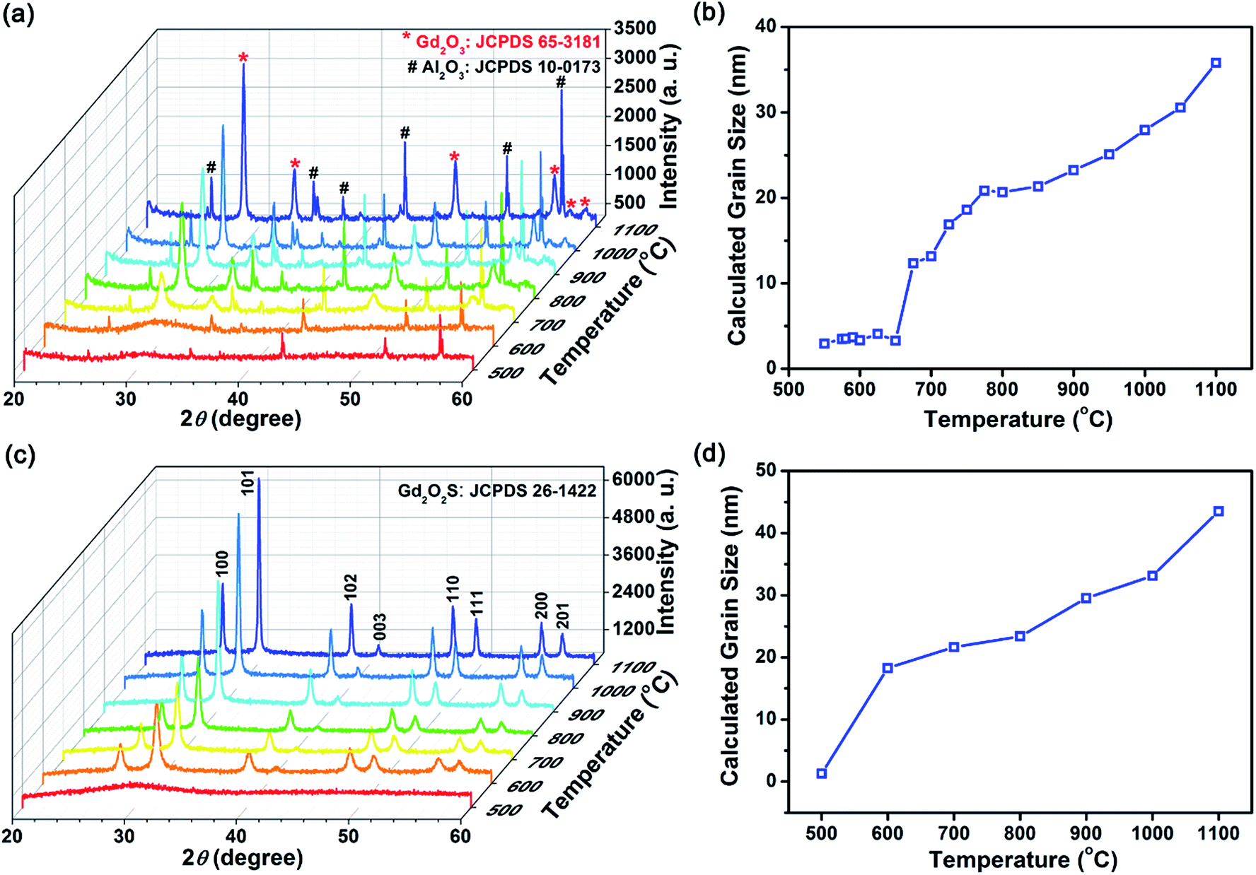 | ||
| Fig. 3 Analyzing the amorphous-to-crystalline phased transition and crystal growth process in (a, b) inert vacuum environment and (c, d) sulfur-rich environment using the XRD. References to JCPDS 65-3181 for Gd2O3, JCPDS 10-0173 for Al2O3 and JCPDS 26-1422 for Gd2O3S were used for the phase identification of our samples. Al2O3 were identified as present for all samples as the sample holder was made of Al2O3 for our quasi in situ XRD measurements. | ||
In a reactive sulfur environment, we observed that the amorphous-to-crystalline phase transition temperature was reduced from 675 to ∼600 °C (see Fig. 3(c) and (d)). At temperatures ≥600 °C, Gd2O2S was formed and grain size was observed to increase from ∼18 to 43 nm as temperature increases to 1100 °C. The reduced phase transition temperature indicated that the reaction of the sulfur vapor with the amorphous precursor was most likely highly exothermic leading to much lesser energy being required to overcome the activation energy. Considering the vapor phase diagram (note: boiling point of sulfur ∼445 °C) and reactivity of the various sulfur polymorphs (i.e., S2 > S6 > S8) in the vapor phase,27 we found that at <600 °C, most of the vapor phase comprises of the less active S6 and S8 forms. Consequently, reaction between the amorphous precursors and sulfur vapor was not likely at <600 °C. From 500 to 600 °C, the amount of active S2 polymorph increases rapidly from 10 to 50 mol%, before reaching ∼99 mol% from temperatures more than 800 °C. Therefore, ∼600 °C is about the lowest required temperature for the effective sulfurization and crystallization of the precursor powders. Scheme 2 shows an overall representation of our proposed gas-aided sulfurization reaction. Further increase in temperature would also lead to grain growth and reduction of lattice defects (see Fig. 3(d)). The continuous removal of sulfur from the reaction zone using the argon carrier gas ensured that the sulfur vapor concentration was sufficiently low to prevent the formation of Gd2S3. Besides lowering the crystallization temperature, the reactive sulfur atmosphere would also likely facilitate the complete decomposition of PVP and Tu and removal of any residual carbon. Thus, only one grain growth zone was observed for the reaction in sulfur (see Fig. 3(d)), instead of the two zones that was earlier observed for the heat treatment of powders in vacuum (see Fig. 3(b)).
In addition, the powder size and morphology after heat treatment at each temperature and condition were characterized using the SEM (see Fig. 1(a) and S5†). From the SEM images, we observed that some particle shrinkage had occurred (from average sizes of 122 to 104–118 nm) and no significant change in the morphology was found. It is likely that the spherical particles shrunk due to the decrease in solid volume during the amorphous-to-crystalline phase transition. Also, since the particles retained its original morphology during the heat treatment process, it verified our earlier suggestions of a PVP coating based on the FTIR results. The PVP coating around the particles had served as a sintering inhibitor which prevented particle fusion that will result in changes to the powder morphology. EDX composition analysis show that the measured composition followed closely with the expected stoichiometric ratios of rare earth dopants and Gd (host), which suggests that the rare earth ions were successfully doped within Gd2O2S (see Table S1†). Furthermore, considering that the estimated grain size of ∼30 nm (Fig. 3(d)) is less than the average particle size of 104–118 nm, polycrystalline spheres of Gd2O2S were prepared using our synthesis method.
3.3 Optical characteristics of Gd2O2S sub-micron sized powders
 | ||
| Fig. 4 Dopant chemistry effects on the upconverted visible and downshifted infrared emissions. The characteristic steady state emission profiles for Er- and Yb-Er-doped samples under monochromatic excitation at 975 nm are shown in (a) and (b), respectively. For all Yb-Er co-doped samples, a constant Er concentration of 1 mol% was used. The relationships between the integrated emissions and the changing Er and Yb concentration for Er- and Yb-Er-doped samples are shown in (c) and (d), respectively. For both Er- and Yb-Er-doped samples, (e) and (f) shows the relationships of the green-to-red emission ratios and average lifetime for the 4I13/2 → 4I15/2 transition (i.e., 1510 nm emission), respectively. | ||
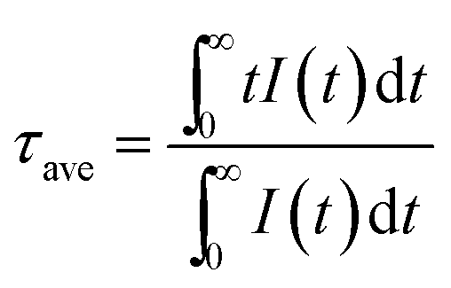
The extent of upconversion compared to downshifting (i.e., visible vs. infrared) were evaluated by comparing the steady state emission profiles for the Er- and Yb-Er doped Gd2O2S (see Fig. 4(c) and (d)). Assuming that no non-radiative multiphonon relaxation occurs from the selected excited state to ground state, the relative fractions of all absorbed near infrared photons at 975 nm that contributed to the visible emission bands (i.e., fvis shown in Table 3) were calculated using the following,29,30
 | (2) |
| Er-doped Gd2O2S | Yb-Er codoped Gd2O2S | ||||||
|---|---|---|---|---|---|---|---|
| Er (mol%) | Int. visible | Int. infrared | fvis (%) | Yb-Er (mol%) | Int. visible | Int. infrared | fvis (%) |
| 0.5 | 4.26 × 10⁵ | 1.15 × 10⁷ | 6.9 | ||||
| 1.0 | 1.38 × 10⁶ | 2.19 × 10⁷ | 11.2 | 4–1 | 7.88 × 10⁶ | 5.56 × 10⁶ | 73.9 |
| 2.0 | 2.22 × 10⁵ | 1.27 × 10⁷ | 3.4 | 6–1 | 1.07 × 10⁷ | 9.25 × 10⁶ | 69.8 |
| 5.0 | 4.44 × 10⁵ | 1.95 × 10⁷ | 4.4 | 8–1 | 1.59 × 10⁷ | 3.28 × 10⁷ | 49.2 |
| 10.0 | 4.59 × 10⁴ | 4.07 × 10⁶ | 2.2 | 12–1 | 6.01 × 10⁶ | 5.23 × 10⁶ | 69.7 |
| 20.0 | 8.88 × 10³ | 8.39 × 10⁵ | 2.1 | 20–1 | 1.30 × 10⁵ | 2.13 × 10⁶ | 10.7 |
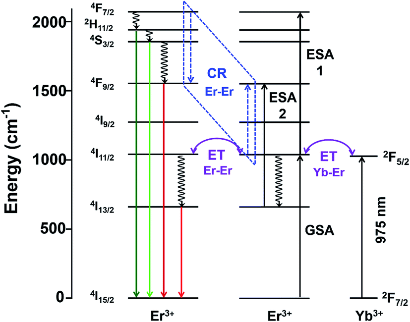 | ||
| Scheme 3 Schematic of proposed electronic and optical transitions of Gd2O2S:Yb-Er sub-micron sized particles. ET: energy transfer, CR: cross-relaxation represented by the dashed lines, ESA: excited state absorption, GSA, ground state absorption. Solid arrows represent radiative transitions, whiles the curly arrows represent non-radiative transitions. | ||
Besides the difference in the extent of upconversion between the Er- and Yb-Er doped samples, the ratio of the green-to-red emission intensities, Igreen/Ired were also distinctly different (see Fig. 4(e)). For example, we observed that the green emissions (i.e., 520–560 nm) were much more intense than the red emissions (i.e., 650–680 nm) for Gd2O2S:Er, especially for Er <6 mol%. At higher Er concentrations, the change in Igreen/Ired was attributed to the concentration quenching effect which would be discussed in the later sections. For the Er-doped systems, due to the small energy difference for the 4F7/2 → 2H11/2 and 2H11/2 → 4S3/2 transitions (see Table S2†), the subsequent multiphonon relaxation from 4F7/2 would rapidly populate 2H11/2 and 4S3/2 levels resulting in the observed green emissions centered at ∼524 and ∼555 nm, respectively when they relax to the 4I15/2 level. The red emission which arises from the 4F9/2 → 4I15/2 transitions occurs after the 4F9/2 level are populated via multiphonon relaxation from the higher 4S3/2 level. However, due to the much larger energy difference and higher number of phonon required to bridge this gap (see Table S2†), the rate of non-radiative relaxation is much lower leading to the observer weaker red emissions for the Er-doped samples. With the addition of Yb to Er-doped Gd2O2S, Igreen/Ired decreased meaning a relative increase of the red emissions (see Fig. 4(e)). The increased red emissions suggested that additional photon transfer pathways to the 4F9/2 levels were possible.30,31 One possible pathway is the non-radiative relaxation from 4I11/2 → 4I13/2 followed by energy transfer upconversion arising from Yb-Er interactions leading to the population of the 4F9/2 levels via 4I13/2 → 4F9/2. Another alternative pathway is via cross-relaxation between the two resonant transitions (4F7/2, 4I11/2) → (4F9/2, 4F9/2) that arises from Er-Er interactions, where the 4F7/2 and 4I11/2 levels are highly populated after the addition of Yb3+. The presence of this cross-relaxation pathway would lead to a decrease in the green emissions due to the reduced population at the 4F7/2 level. However, since the Er concentration is relative low for the Yb-Er co-doped samples (i.e., ∼1 mol%), the energy transfer efficiency between the Er-Er pairs will likely be poor, and the Yb-Er interactions will more strongly influence the emission distribution for the co-doped samples.
For both Er- and Yb-Er doped systems, there exists an optimum dopant concentration where the most intense steady state emission intensities (both visible and infrared) were measured. There would be insufficient emitting centers at low dopant concentrations to deliver radiative emissions since the interactions between the ion pairs will be too weak due to the large separation distances. When the dopant concentrations are too high, concentration quenching occurs. Concentration quenching is determined mainly by the dipole–dipole interactions between rare earth ions, and the quenching effects vary according to R−6, where R is the interionic distance between rare earth ion pairs.1,2 The emission is completely quenched for ions separated at a distance shorter than a critical interionic distance (∼0.5 to 2 nm, depending on the host), whereas ions separated by a distance longer than R is not subjected to complete quenching.1,2 Using the integrated emission profiles, we found that the optimum concentration for the Er- and Yb-Er doped Gd2O2S were Er ∼ 1 mol% and Yb:Er ∼ 8:1 mol%/mol%, respectively (see Fig. 4(c) and (d)). Since the results for the integrated emissions for Er doped Gd2O2S was quite noisy, the optimum concentration was not as obvious. The large variation of the integrated intensities was partly attributed to variable powder packing densities as a consequence of variations in average powder sizes.32 Consequently, we have fitted the obtained data points to a trendline based on the moving average to identify the optimum concentration of Er ∼ 1 mol%. Increasing Er beyond 1 mol% led to concentration quenching that resulted in the overall reduction of all emissions. For the Yb-Er co-doped samples with Er maintained at a constant of 1 mol%, increasing Yb beyond 8 mol% led to the Yb-Yb concentration quenching and subsequent reduction of Yb-Er resonant energy transfer.19,30,31,33
The emission intensity is dictated by the emission oscillator strength of Er which is correlated to both the branching ratios of the radiative transitions and the radiative lifetime of the excited states. The radiative lifetime characterizes the contribution of both radiative and non-radiative relaxation pathways from a specific excited state, where these lifetime measurements are particularly sensitive to the fluctuations in local atomic order and interionic distances of the rare-earth ions.1,34 Therefore, the optimum dopant concentration can be verified by measuring the radiative lifetime of the excited states. Compared to the non-linear upconversion pathways, since the downshifted infrared emission occurs via a linear optical process where the emission intensity is dependent on one pathway, the optimum dopant concentrations were elucidated from the lifetime of the 4I13/2 → 4I15/2 transition (see Fig. 4(f) and S6†). The optimum concentration was ∼1 mol% for Er doped Gd2O2S based on the measured lifetime, which was consistent with the earlier results from the integrated emissions determined from the steady state spectra (see Fig. 4(c)). For the Yb-Er co-doped Gd2O2S, a significant reduction in the measured lifetime was observed. For example, the measured lifetimes for Gd2O2S:Er (1 mol%) and Gd2O2S:Yb-Er (4–1 mol%/mol%) were 1729 and 571 μs, respectively, which represented an almost 3-fold decrease. The observed lifetime reduction was attributed to either back energy transfer from Er to Yb followed by energy migration via Yb coupled with non-radiative relaxation or the increase in probability for non-radiative decay as a consequence of the increase of population of the 4I13/2 level due to energy transfer from Yb to Er. Since these lifetime measurements are very sensitive to any fluctuations in interionic separation distances (e.g., Yb-Er, Yb-Yb), it was more difficult to identify the optimum concentration due to the lower average lifetimes coupled with larger variations for Yb-Er co-doped Gd2O2S. However, we could estimate that the optimum Yb concentration should be between 6 to 12 mol% co-doped with 1 mol% of Er based on the lifetime results (see Fig. 4(f)). This estimated range is in good agreement with our earlier results of an optimum 8 mol% of Yb co-doped with 1 mol% of Er from the integrated emissions determined from the steady state spectra (see Fig. 4(d)).
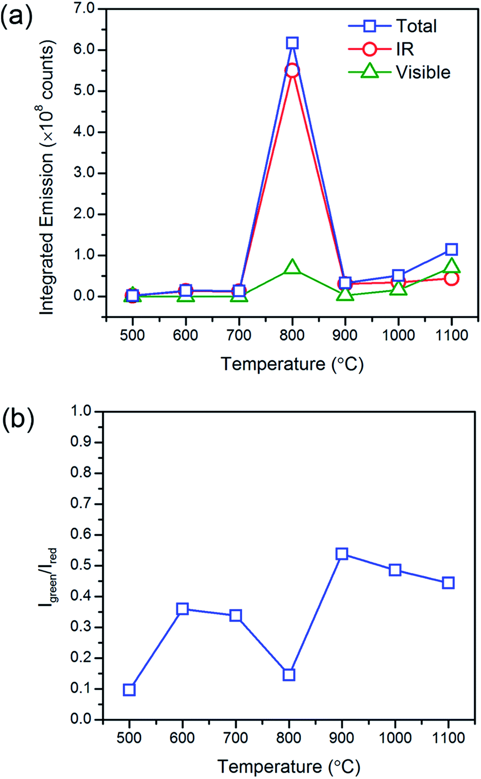 | ||
| Fig. 5 Heat treatment temperature effects on the upconverted visible and downshifted infrared emissions. The (a) characteristic steady state emission profiles and (b) green-to-red emission intensity ratios of Gd2O2S:Yb8Er1 (8 mol% Yb and 1 mol% Er) under monochromatic excitation at 975 nm show that the optimum heat treatment temperature is at ∼800 °C. | ||
At temperatures above 800 °C, one would have expected further increase in emissions with the further reduction in lattice defects that accompanies grain growth. However, we observed a significant decrease in the emission intensities and increase in the Igreen/Ired ratios at the much higher temperatures. It has been previously reported that non-uniform surface segregation of Yb and Er led to localized compositional variations within the host which subsequently resulted in a reduction in emission intensities and changes in the Igreen/Ired ratio.35 Therefore, the unexpected reduction in emissions was most likely associated with the increased diffusion of dopant ions at the much higher temperatures leading to the formation of non-uniform dopant distributions. The observed increase in Igreen/Ired ratio also suggests a weaker Yb-Er interactions which could occur if the interionic separation of Yb-Er ion pairs have changed. EDX image scans to obtain the elemental map would allow us to verify any changes in dopant distribution. However, due to the low dopant concentrations (≪10 mol%, near lower limits of instrument) and significant spectral peak overlap of the Lα lines of Er and Yb, it would be difficult to deconvolute the signals to obtain accurate Yb and Er elemental maps. Therefore, elemental maps from Gd2O2S:Er20 (i.e., 20 mol% Er) heat treated at 1000 °C were measured to assess dopant diffusion characteristics and evaluate the uniformity of dopant distribution (see Fig. 6 and S7†). The elemental maps were next analyzed using the contour plot function in OriginLab Pro© to objectively identify regions of varying EDX signal intensities and element distribution. Comparing the elemental map of Er with Gd, O and S, Er shows an obvious non-uniform distribution. The non-uniform dopant distribution could have led to either increased interionic separations (e.g., Yb-Er) which results in weaker interactions and emissions or reduced interionic separations (e.g., Yb-Yb or Er-Er) which results in concentration quenching. Both of these scenarios would have led to the observed overall reduction in emission intensities and increase in the Igreen/Ired ratios. It should be noted that the observed incremental increase in the luminescent emissions as temperatures increased from 900 to 1100 °C was most likely due to the removal of the residual carbon and the reduction of lattice defects that accompanies grain growth.
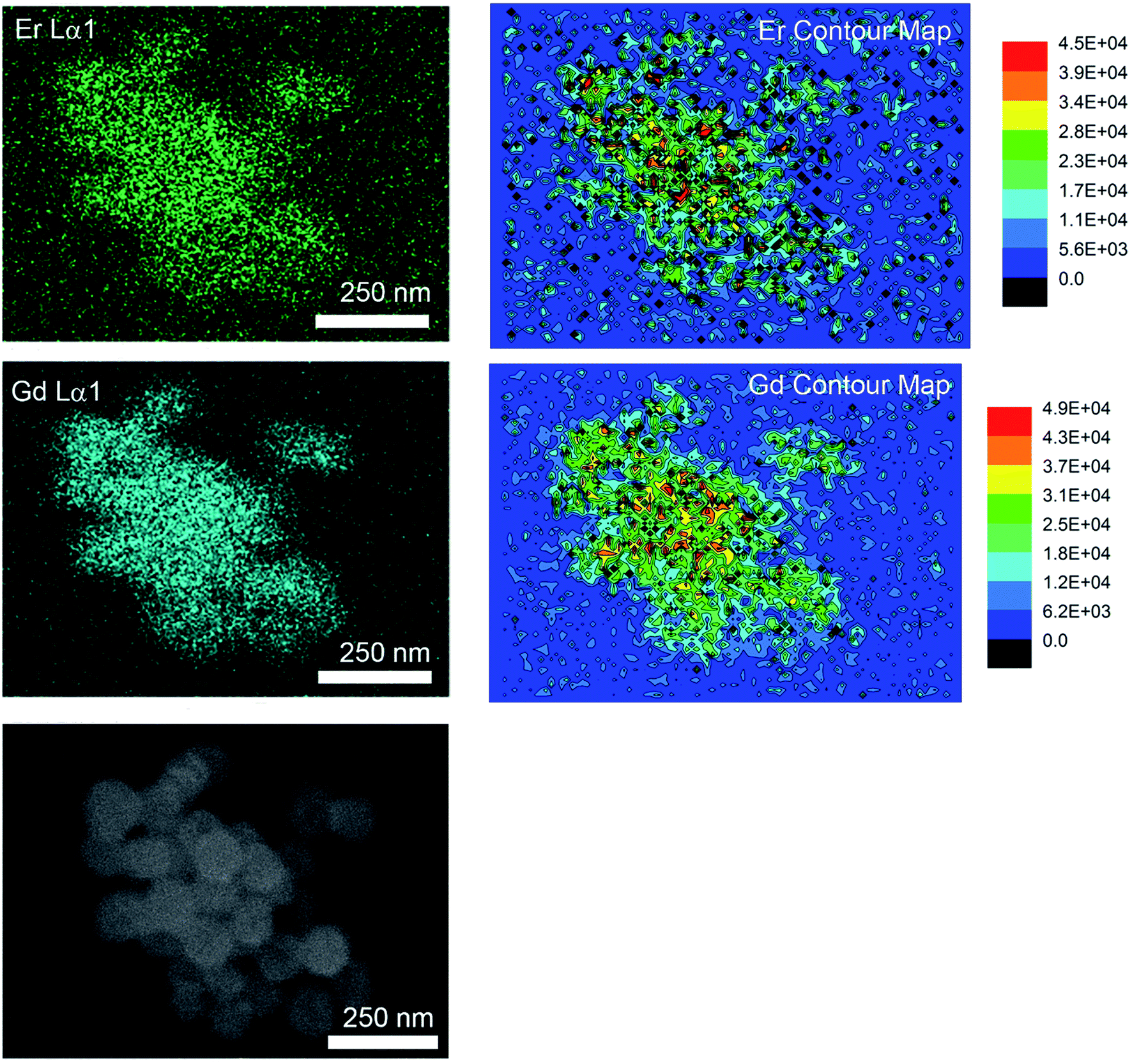 | ||
| Fig. 6 EDX element map images and corresponding contour map of Gd2O2S:Er20 (20 mol% Er) sub-micron sized particles. The difference in element distribution of Gd and Er elements shown in the contour maps indicates the non-uniformity of Er distribution in Gd2O2S sub-microparticles at high Er dopant concentration of 20 mol%. Slight difference in the measured intensities observed reflected on the Gd contour map is a consequence of the difference in sample elevation (see SEM image at the lower left hand panel). | ||
4. Summary
In this work, we report the synthesis of uniform ∼104–118 nm Gd2O2S spheres using a two-step process: (1) synthesis of amorphous [Lny–Tuz]3+ precursor particles using the solvothermal method where PVP was used to control particle morphology as well as to successfully inhibit particle sintering during the subsequent gas-aided sulfurization, followed by (2) crystallization to form Gd2O2S polycrystalline spheres upon precursor decomposition in a sulfur-rich environment at elevated temperatures. The crystallization and sulfurization processes are investigated by monitoring the crystal growth at different temperatures and environments using mainly results from X-ray diffraction and analysis of the thermal decomposition profile of the precursor particles. It was found that Gd2O2S crystallization occurs by ∼600 °C in a sulfur-rich environment, whilst any residual carbon from the decomposition of PVP and Tu was completely removed by ∼800 °C. In addition, the optimum dopant concentrations were found to be Gd2O2S:Er1 (1 mol% of Er) and Gd2O2S:Yb8Er1 (8 mol% Yb and 1 mol% Er) using the results of our steady state and time resolved luminescent measurements. The introduction of Yb as a co-dopant significantly increased the emission intensities and upconversion efficiencies as well as reduced green-to-red emission intensity ratio, which is mainly due to the higher absorption cross sections of Yb. Our results show that the maximum emission intensities were obtained for a heat treatment temperature of 800 °C. At much higher temperatures, non-uniform dopant distribution resulted in reduced emission intensities due to inefficient rare earth interactions.Acknowledgements
MC Tan, XY Zhao and SQ He would like to gratefully acknowledge the funding support from the Agency for Science, Technology and Research Public Sector Fund (Project number 1321202097) and Singapore University of Technology and Design-Massachusetts Institute of Technology International Design Centre (Project number IDG31400106) and the Ministry of Education (Project number MOE2014-T2-2-145). MC Tan would also like to acknowledge the support from the National Institute of Health, NIH EB 018378.References
- M. C. Tan, D. J. Naczynski, P. V. Moghe and R. E. Riman, Aust. J. Chem., 2013, 66, 1008–1020 CrossRef CAS.
- X. Zhao, S. He and M. C. Tan, J. Mater. Chem. C, 2016, 4, 8349–8372 RSC.
- D. J. Naczynski, M. C. Tan, R. E. Riman and P. V. Moghe, J. Mater. Chem. B, 2014, 2, 2958–2973 RSC.
- R. Naccache, F. Vetrone and J. A. Capobianco, ChemSusChem, 2013, 6, 1308–1311 CrossRef CAS PubMed.
- Y. Tong, X. Zhao, M. C. Tan and R. Zhao, Sci. Rep., 2015, 5, 16761 CrossRef CAS PubMed.
- R. Martín-Rodríguez, S. Fischer, A. Ivaturi, B. Froehlich, K. W. Krämer, J. C. Goldschmidt, B. S. Richards and A. Meijerink, Chem. Mater., 2013, 25, 1912–1921 CrossRef.
- S. Fischer, R. Martín-Rodríguez, B. Fröhlich, K. W. Krämer, A. Meijerink and J. C. Goldschmidt, J. Lumin., 2014, 153, 281–287 CrossRef.
- G. V. Anan'eva, E. I. Gorokhova, V. A. Demidenko, V. A. Parfinskii and O. A. Khristich, J. Opt. Technol., 2005, 72, 58–61 CrossRef.
- D. Yuan, M. C. Tan, R. E. Riman and G. M. Chow, J. Phys. Chem. C, 2013, 117, 13297–13304 CAS.
- J. Njj, Chem. Mater., 2011, 23, 3714 CrossRef.
- E. Cwe Van, Phys. Med. Biol., 2002, 47, R85 CrossRef.
- L. Hernandez-Adame, N. Cortez-Espinosa, D. P. Portales-Pérez, C. Castillo, W. Zhao, Z. N. Juarez, L. R. Hernandez, H. Bach and G. Palestino, J. Biomed. Mater. Res., Part B, 2017, 105, 605–615 CrossRef CAS PubMed.
- Y. Song, H. You, Y. Huang, M. Yang, Y. Zheng, L. Zhang and N. Guo, Inorg. Chem., 2010, 49, 11499–11504 CrossRef CAS PubMed.
- Y. Ding, J. Gu, J. Ke, Y.-W. Zhang and C.-H. Yan, Angew. Chem., Int. Ed., 2011, 50, 12330–12334 CrossRef CAS PubMed.
- L. Lei, S. Zhang, H. Xia, Y. Tian, J. Zhang and S. Xu, Nanoscale, 2017, 9, 5718–5724 RSC.
- P. O. Andreev and P. P. Fedorov, Russ. J. Inorg. Chem., 2013, 58, 724–727 CrossRef CAS.
- T. Zhang, J. Gu, Y. Ding, Y.-W. Zhang and C.-H. Yan, ChemPlusChem, 2013, 78, 515–521 CrossRef CAS.
- S. Gai, C. Li, P. Yang and J. Lin, Chem. Rev., 2014, 114, 2343–2389 CrossRef CAS PubMed.
- J. A. Capobianco, F. Vetrone, J. C. Boyer, A. Speghini and M. Bettinelli, J. Phys. Chem. B, 2002, 106, 1181–1187 CrossRef CAS.
- M. A.-F. Basha, Polym. J., 2010, 42, 728–734 CrossRef CAS.
- S.-H. Yu, J. Yang, Z.-H. Han, Y. Zhou, R.-Y. Yang, Y.-T. Qian and Y.-H. Zhang, J. Mater. Chem., 1999, 9, 1283–1287 RSC.
- J. Polte, CrystEngComm, 2015, 17, 6809–6830 RSC.
- J. Wang, Y. Xu, M. Hojamberdiev, M. Wang and G. Zhu, Mater. Chem. Phys., 2010, 119, 169–174 CrossRef CAS.
- R. G. Kumari, V. Ramakrishnan, M. L. Carolin, J. Kumar, A. Sarua and M. Kuball, Spectrochim. Acta, Part A, 2009, 73, 263–267 CrossRef PubMed.
- S. Wang, Q. Gao and J. Wang, J. Phys. Chem. B, 2005, 109, 17281–17289 CrossRef CAS PubMed.
- Y. K. Du, P. Yang, Z. G. Mou, N. P. Hua and L. Jiang, J. Appl. Polym. Sci., 2006, 99, 23–26 CrossRef CAS.
- J. R. West, Ind. Eng. Chem., 1950, 42, 713–718 CrossRef CAS.
- W. T. Carnall, G. L. Goodman, K. Rajnak and R. S. Rana, J. Chem. Phys., 1989, 90, 3443–3457 CrossRef CAS.
- J. F. Suyver, J. Grimm, M. K. van Veen, D. Biner, K. W. Krämer and H. U. Güdel, J. Lumin., 2006, 117, 1–12 CrossRef CAS.
- F. Vetrone, J. C. Boyer, J. A. Capobianco, A. Speghini and M. Bettinelli, J. Phys. Chem. B, 2003, 107, 1107–1112 CrossRef CAS.
- Y. Li and Y. Pan, Optik, 2013, 124, 5131–5134 CrossRef CAS.
- Y. Sheng, L.-D. Liao, A. Bandla, Y.-H. Liu, J. Yuan, N. Thakor and M. C. Tan, Mater. Sci. Eng., C, 2017, 70, 340–346 CrossRef CAS PubMed.
- P. Yang, P. Deng and Z. Yin, J. Lumin., 2002, 97, 51–54 CrossRef CAS.
- A. Polman, Phys. B, 2001, 300, 78–90 CrossRef CAS.
- D. Yuan, G. Shun Yi and G. M. Chow, J. Mater. Res., 2011, 24, 2042–2050 CrossRef.
Footnotes |
| † Electronic supplementary information (ESI) available. See DOI: 10.1039/c7ra05041k |
| ‡ Authors contributed equally to this work. |
| This journal is © The Royal Society of Chemistry 2017 |