 Open Access Article
Creative Commons Attribution 3.0 Unported Licence
Fabrication of In2O3/ZnO@Ag nanowire ternary composites with enhanced visible light photocatalytic activity
Hairui Liu *a,
Chunjie Hua,
Haifa Zhaia,
Jien Yanga,
Xuguang Liu
 b and
Husheng Jia*b
aCollege of Physics & Materials Science, Henan Normal University, Henan Key Laboratory of Photovoltaic Materials, Xinxiang 453007, PR China. E-mail: liuhairui1@126.com; Tel: +86 18738589806
bKey Laboratory of Interface Science and Engineering in Advanced Materials (Taiyuan University of Technology), Ministry of Education, Taiyuan, Shanxi 030024, P. R. China
First published on 26th July 2017
Abstract
Herein, an In2O3/ZnO@Ag ternary photocatalyst was synthesized by a facile co-precipitation process. The results indicated that Ag nanowires were encapsulated by In2O3/ZnO compounds, and the obtained In2O3/ZnO@Ag photocatalyst showed strong absorption in the visible light region. The photoluminescence (PL) emission intensity gradually decreased for In2O3/ZnO@Ag as compared to that for the In2O3/ZnO composites and pure ZnO. The as-prepared In2O3/ZnO@Ag composites exhibited excellent visible light photocatalytic activities for degradation of organic contaminants (methyl orange and 4-nitrophenol). The enhancement of photocatalytic activity was ascribed to the extended visible light absorption region by Ag nanowires and the formation of close hetero-structure by the matched band structures of In2O3 and ZnO. Finally, a possible photocatalytic mechanism was proposed based on the matched energy band structure and active species trapping experiments.
1. Introduction
In recent years, environmental pollution and energy shortage have created serious social and economic issues for the economic development of modern human society.1–3 Semiconductor-based photocatalysis has been widely employed as a highly efficient technique to overcome these issues.4–6 Zinc oxide (ZnO), as a promising photocatalyst, has attracted widespread interests owing to its outstanding electrical and optical properties, low-cost, high biological safety, versatile shapes and structures, environmental friendliness, and strong photocatalytic degradation ability of organic pollutants under UV light.7–10 However, pure ZnO materials show poor absorption of visible light; this limits the efficient utilization of solar energy. Another main drawback of ZnO is the rapid recombination of photo-induced electron–hole pairs that results in low quantum yield for any photocatalytic reaction.11–13 Therefore, extension of the absorption edge of ZnO to the visible light region for the utilization of about 43% solar spectrum while suppressing the recombination of photo-generated electron–hole pairs is still a great challenge for scientists. In the past few years, various modification strategies, including sensitization, semiconductor coupling, doping and noble metal deposition, have been employed to activate ZnO photocatalysis under visible light.14–17 Among these, the most effective strategy is coupling ZnO with a narrow band-gap semiconductor with matched band potential, which has been proven to be a feasible approach. Considering that the band gap of In2O3 (Eg = 2.8 eV) is lower than that of ZnO (Eg = 3.2 eV) and its valence and conduction band alignments are staggered relative to those of ZnO, a type II heterojunction can be formed by coupling them together.18–21 The formation of type II heterostructures has been recognized as an attractive route to overcome the limitations of ZnO because it promotes efficient charge separation, enlarges the effective contact interfaces, and improves the optical absorption.22,23In the binary system, the relatively narrow region of visible light response and relatively lower separation efficiency of electron–hole pairs limit its practical applications. Ternary system construction composites have been extensively investigated via introduction of an additional constituent, such as Ag, Au, carbon, and graphene oxide (GO), to the binary heterojunction.24–29 Ternary system construction not only changes the nature of charge transfer but also broadens the region of light absorption. For instance, a CuxO/ZnO@Au heterojunction exhibits improved photocurrent generation and higher photocatalytic activity as compared to its binary counterpart CuxO/ZnO due to the addition of Au. Through decorating Au on the surface of a CuxO/ZnO composite, a fluent electron transfer from CuxO to ZnO and eventually to Au can be achieved, whereas the photo-induced holes remain in the conduction bands of CuxO; this can lead to multistep charge transfer.30 Hierarchical Ag/AgBr/TiO2 composites with porous structures have been fabricated and displayed enhanced visible light photocatalytic activities,31 in which AgBr as the main active component generates electron–hole pairs. The Ag nanoparticles act not only as an active component generating energetic electrons by surface plasmon resonance (SPR) under the irradiation of visible light, but also as an electron-transfer media to enhance the stability of the photocatalyst. Wu et al. fabricated porous-structured Ag/ZnO/ZnFe2O4 ternary composites via a facile calcination process.25 The synthesized ternary composites show significantly enhanced photocatalytic activity towards the degradation of an organic dye as compared to the binary counterpart ZnO/ZnFe2O4. The Ag/AgCl/Ag2O heterostructure composites with enhanced photocatalytic activities for the degradation of Ciprofloxacin have been successfully synthesized; it has been demonstrated that Ag can be integrated into a Z-scheme photocatalytic system and acts as an excellent electron transfer mediator to enhance the oxidizing and reducing powers for photocatalysis.32 Other ternary component hybrid examples have been intensively investigated, in which a metal acts as the electron-transfer mediator or as an SPR source to enhance visible light absorbance and promote efficient charge separation.23,33–35
Herein, we report the preparation of an In2O3/ZnO@Ag ternary component photocatalyst, with enhanced visible light photocatalytic activity, via a facile co-precipitation process. The microstructure, phase, and optical properties of the samples have been investigated. The visible light photocatalytic activities of the as-prepared composites are investigated via degradation of MO or 4-NP. As expected, the as-obtained In2O3/ZnO@Ag ternary component exhibited excellent charge separation efficiency and visible light photocatalytic performance. Finally, the charge transfer and probable photocatalytic mechanism have been discussed and proposed on the basis of optical characterization, band gap structure, and reactive species reaction.
2. Experimental details
2.1 Formation of the In2O3/ZnO@Ag ternary heterojunction photocatalyst
Ag nanowires were fabricated by a classical polyol process.13 The purified Ag nanowires were mixed into 1 mmol L−1 ethanol for the fabrication of In2O3/ZnO@Ag ternary composites. First, 0.18 mmol ZnAc and 0.06 mmol In(NO3)3 were added to deionized water and thoroughly mixed under stirring until a uniform mixed solution was formed. Then, 10 ml of Ag suspension and 8 ml of TEA were added in sequence to the abovementioned solution. The mixed solution was heated via a water-bath method at 90 °C for 2 h. The obtained precipitates were centrifuged, washed several times with deionized water and ethanol, and dried in an oven at 60 °C. The final In2O3/ZnO@Ag composites were thus obtained via annealing at 200 °C for 1 h. For comparison, In2O3/ZnO and Ag/ZnO composites were also prepared under the same condition without the addition of Ag nanowires and In(NO3)3. The In2O3/ZnO/Ag mixture was fabricated by ball milling pure In2O3, ZnO, and Ag.2.2 Characterization
The crystal structures were studied by powder X-ray diffraction (XRD). The morphologies and microstructures of the obtained samples were measured by field emission scanning electron microscopy (FESEM; JSM-6700F, Japan) and high resolution transmission electron microscopy (FE-SEM SUPRA™ 40). Chemical states of the samples were analyzed using X-ray photoelectron spectroscopy (XPS; PHI-5300, ESCA, USA). The UV-vis diffused reflectance spectra (UV-vis DRS) of the samples were obtained using a UV-3600 spectrophotometer. Photoluminescence (PL; Renishaw1000, UK) spectra were obtained at room temperature using a He–Cd laser as the excitation light source at 325 nm.The photocatalytic activities of the as-prepared samples were evaluated by the photocatalytic degradation of methyl orange (MO) and 4-nitrophenol (4-NP). First, 10 mg of the as-prepared In2O3/ZnO@Ag photocatalyst was ultrasonically dispersed in 50 ml of 10 mg L−1 MO or 10 ml of 1 mg L−1 4-NP aqueous solution in a quartz glass container; the mixture was magnetically stirred for 30 minutes in the dark. Then, visible light irradiation was carried out using a 300 W Xe lamp with an optical cut-off filter (λ ≥ 420 nm) as the light source. At given intervals, 3 ml aliquots were sampled and analyzed by obtaining variations in the absorption band (464 nm and 317 nm) in the UV-vis spectra of MO or 4-NP, respectively.
2.3 Photoelectrochemical characterization
The photoelectrochemical experiments, including photocurrent, electrochemical impedance spectroscopy (EIS), and linear sweep voltammetry (LSV) measurements were carried out using an electrochemical workstation (CHI-660C, Chenhua Instrument, China). A Pt wire and Ag/AgCl electrode were used as the counter electrode and reference electrode, respectively. The working electrodes were prepared as follows: 0.2 g of the obtained photocatalyst was mixed with 0.1 g of polyethylene glycol and 3 ml of water; then, the mixture was ground to form a slurry. Next, the slurry was coated onto a pre-cleaned 1 cm × 1 cm FTO glass electrode, dried, and calcined at 450 °C for 30 min in an oven. A 300 W Xe lamp with an optical cut-off filter (λ ≥ 420 nm) was used as the excitation light source. A Na2SO4 aqueous solution (0.1 M) was used as the electrolyte. EIS measurements were carried out in a 0.1 M Na2SO4 solution at an open circuit potential over a frequency range from 105 to 10−1 Hz. LSV measurements plots of the samples were obtained at a scan rate of 100 mV s−1.3. Result and discussion
3.1 Structural characterization
The phase composition and crystal properties of the as-prepared samples were analyzed by X-ray diffraction (XRD), as shown in Fig. 1. It was found that the pure ZnO sample had sharp peaks at 31.8°, 34.4°, 36.3°, 47.6°, 56.7°, 62.9°, 68.0°, and 69.2°. The positions of all the peaks can be indexed to the wurtzite ZnO structure (JCPDS File no. 36-1451) and correspond to (100), (002), (101), (102), (110), (103), (112) and (201). For the obtained In2O3/ZnO heterojunction, there are four new sharp diffraction peaks at the 2θ values of 30.1°, 35.5°, 51.1°, and 60.7°, which can be indexed to the (222), (400), (440), and (622) crystal planes of the body-centered cubic structure of In2O3 (JCPDS 71-2194), respectively. For the In2O3/ZnO@Ag sample, three new characteristic peaks related to the face-centered-cubic (fcc) metallic Ag (JCPDS 04-0783) (111), (200), and (220) planes are observed in the diffraction pattern, and other two sets of diffraction peaks indexed to orthorhombic In2O3 and wurtzite ZnO do not change; this reveals that the introduction of Ag nanowires does not change the crystal phase and crystallinity of In2O3 and ZnO.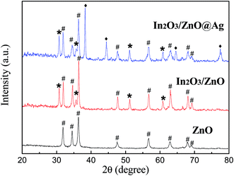 | ||
| Fig. 1 XRD patterns of pure ZnO, In2O3/ZnO heterojunction, and In2O3/ZnO@Ag ternary composites (#: ZnO; *: In2O3; ♦: Ag). | ||
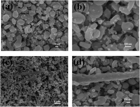
The microscopic morphologies and structures of the In2O3/ZnO and In2O3/ZnO@Ag composites were investigated using FESEM. Fig. 2(a and b) present the SEM images of the obtained In2O3/ZnO heterojunction. It can be clearly observed that ZnO presents a hexagonal disk-structure with an average diameter of 200 nm and a thickness of about 40 nm; small and uniform In2O3 nanoparticles are highly dispersed on the surface of the ZnO disks. The In2O3 nanoparticles have a size distribution of about 20–40 nm. Similarly, Fig. 2(c and d) show the surface morphology of the In2O3/ZnO@Ag ternary composites; it can be found that the In2O3/ZnO@Ag ternary composites present rod-like shapes, with well-dispersed In2O3/ZnO nanoparticles coated on the surface of the Ag nanowires.
Fig. 3(a) shows a low-magnification TEM image of an In2O3/ZnO@Ag ternary composite. Under the TEM observation, a dark nanowire with a diameter of about 120 nm can be observed in the center, which is consistent with the diameter of Ag nanowires. The thickness of the shell encapsulated by the ZnO/In2O3 composites is 150–200 nm. In2O3 nanoparticles with a diameter of 20 nm are dispersed on the surface of the ZnO nanodisks, as seen from Fig. 3(b).
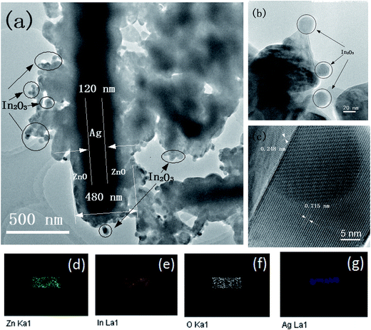 | ||
| Fig. 3 (a and b) TEM image, (c) HRTEM image, and (d–g) Zn, In, O, and Ag elemental mappings of an individual In2O3/ZnO@Ag composite. | ||
In the HRTEM image of Fig. 3(c), a clear and sharp interface further confirms that ZnO and In2O3 are in intimate contact, which is beneficial for transfer of charge at the interface. The measured lattice spacings of 0.248 nm and 0.715 nm for the crystalline planes correspond well to the (002) plane of hexagonal wurtzite ZnO and the (110) crystalline plane of the body-centered cubic structured In2O3, respectively.36,37 The good crystalline quality and the sharp interface between ZnO and In2O3 are beneficial for the separation of the photo-generated carriers. The elemental mappings of Zn, In, O, and Ag are shown in Fig. 3(d–g). It can be found that the Zn, In, and O elements are concomitant and have uniform distribution in the micro-rod; this further indicates that ZnO and In2O3 are nested within each other. However, the size of the Ag element distribution is narrow; this confirms that Ag is distributed as a bearing core coated with peripherally distributed Zn, O, and In. Based on the abovementioned results, it is verified that Ag nanowires are successfully encapsulated by the In2O3/ZnO nanoparticles.
To verify the existence of ZnO, In2O3, and the chemical states of the Ag species, the X-ray photoelectron spectrum (XPS) of In2O3/ZnO@Ag was obtained (Fig. 4). The XPS spectrum of Zn 2p for the In2O3/ZnO@Ag composites (Fig. 4(a)) has two major peaks centered at 1044.2 and 1021.4 eV, which are assigned to Zn 2p1/2 and Zn 2p3/2, respectively, indicating the Zn(II) oxidation state in ZnO.25,38 On comparing the peak positions of Zn 2p for pure ZnO and In2O3/ZnO@Ag composites, it can be found that the peak positions of Zn 2p shift to higher binding energies when compared with those of pure ZnO. In terms of the In 3d spectrum (Fig. 4(b)), there are two characteristic peaks centered at 444.16 and 451.73 eV that can be attributed to In 3d5/2 and In 3d3/2, respectively, which indicate the presence of In3+ in the ZnO/In2O3 composites.39 It can be found that the In 3d peak positions of the samples were shifted to higher values when compared with that of pure In2O3. The slight shift in the binding energies of Zn 2p and In 3d can be ascribed to a shift of the Fermi energy level of ZnO and In2O3, which is caused by the strong interaction between ZnO, In2O3, and Ag in the composites. In the O 1s XPS spectrum (Fig. 4(c)), the asymmetric profile can be divided into two symmetrical peaks centered at 530.05 eV and 532.22 eV. The peak located at 530.05 eV is assigned to the lattice oxygen binding with In and Zn (denoted as In–O and Zn–O). In addition, the peak centered at 532.22 eV is associated with the surface-absorbed oxygen species.26,40 The surface oxygen species can produce primary active superoxide radicals and hydroxyl radicals, which are capable to trap photo-induced electrons and holes. Thus, the surface-absorbed oxygen species are very important for photocatalysis.25 From Fig. 4(d), it can be seen that two peaks centered at 368.1 eV and 374.1 eV are ascribed to Ag 3d5/2 and Ag 3d3/2 of metallic Ag0 species, respectively, which confirm the existence of Ag NWs in the composites.41
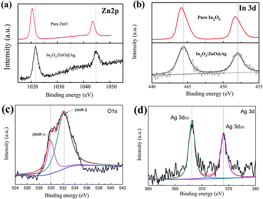 | ||
| Fig. 4 High-resolution XPS curves of the In2O3/ZnO@Ag composites for the elements: (a) Zn 2p, (b) In 3d, (c) O 1s, and (d) Ag 3d. | ||
Fig. 5(a) shows the UV-vis absorption spectra of the bare ZnO, Ag nanowires, In2O3/ZnO, and In2O3/ZnO@Ag composites. The ZnO nanodisks exhibit intense optical absorption in the UV region, and a steep absorption edge is located at around 380 nm.30 The as-prepared In2O3/ZnO heterojunctions exhibit a significant enhancement in the light absorption intensity and an obvious red-shift of the absorption edge to the visible light region, which is due to the addition of In2O3. The SPR peaks of silver nanowires occur at 350 and 380 nm. The maximal peak at 380 nm corresponds to the transverse plasmon resonance of the nanowires, and the weaker peak appearing at 350 nm is attributable to the quadrupole resonance excitation of the nanowires.42 In addition, the strength of the absorption after 380 nm slightly decreases, with a long tail over the wavelength range from 380 nm to 800 nm. While for ternary In2O3/ZnO@Ag composite, the widest visible light absorption was achieved, indicating that there was a synergistic effect between ZnO, In2O3, and Ag. That is to say, In2O3/ZnO@Ag ternary composites could efficiently utilize visible light and produce more photo-generated carriers, resulting in higher photocatalytic activity.
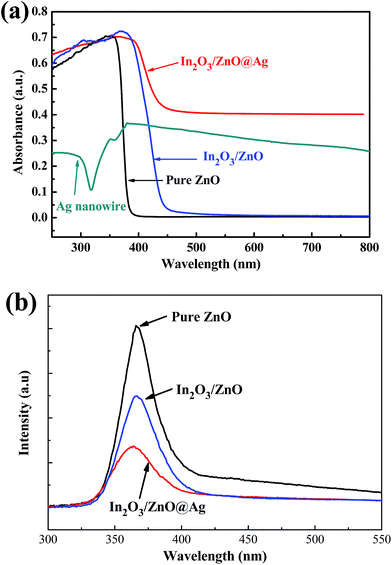 | ||
| Fig. 5 UV-vis absorption (a) and photoluminescence (b) spectra of the pure ZnO, In2O3/ZnO, and In2O3/ZnO@Ag composite. | ||
To investigate the photocatalytic mechanism, PL spectroscopy measurements for pure ZnO, In2O3/ZnO heterojunction, and In2O3/ZnO@Ag ternary composite were conducted, and the results are shown in Fig. 5(b). Compared with pure ZnO, binary In2O3/ZnO composites exhibit a significant PL quenching that implies that the recombination rates of the photo-generated electron–hole pairs in the samples have been restrained. In particular, the In2O3/ZnO@Ag ternary sample displays lowest PL intensity; this indicates that for the In2O3/ZnO@Ag ternary sample, the photo-induced electron–hole pairs possess highest transfer efficiency than that for other samples. That is to say, Ag nanowire-modified In2O3/ZnO structures possess highest ability to separate the photo-generated electron–hole pairs that would boost the photocatalytic reaction.24,43
The photocurrent transient response is an available method to evaluate the separation efficiency and recombination rate of photo-induced electron–hole pairs in the composite photocatalysts. In general, a higher photocurrent implies higher electrons-hole separation efficiency, thus leading to higher photocatalytic activity. The photocurrent transient responses of ZnO, In2O3/ZnO, and In2O3/ZnO@Ag ternary composite samples under visible light were measured and are shown in Fig. 6(a). Notably, the photocurrent value of In2O3/ZnO@Ag ternary composite is several times higher than that of pristine ZnO and In2O3/ZnO, which implies that the In2O3/ZnO@Ag composite has a higher separation rate of photo-generated electron–hole pairs under the irradiation of visible light.44,45 To further explore the separation of photo-induced electron–hole pairs and transport of interfacial electron, the electrochemical impedance spectroscopy (EIS) was conducted for these samples, and the results are shown in Fig. 6(b). It can be observed that the impedance arc radius of the In2O3/ZnO@Ag ternary composite is much smaller than that of the pure ZnO and In2O3/ZnO hybrids; this indicates that the In2O3/ZnO@Ag ternary composites possess lowest electron transfer resistance and best interfacial electron transfer performance.46 The LSV plots of the samples were also measured, as shown in Fig. 6(c). The photocurrent density of bare ZnO and In2O3 film was 0.92, and 1.63 mA cm−2 at 1.2 V (vs. Ag/AgCl). The bare ZnO film exhibited the least photocurrent response due to its wide bandgap. Under the same condition, the ZnO/In2O3 film showed higher photocurrent at 3.82 mA cm−2, and the In2O3/ZnO@Ag ternary composite film exhibited the highest photocurrent density of 5.27 mA cm−2 at 0.6 V (vs. Ag/AgCl). This suggests that In2O3/ZnO@Ag exhibited stronger ability for the separation of photo-generated electron–hole pairs than bare ZnO, In2O3, and ZnO/In2O3, which can be ascribed to the enhancement of visible light absorption capacity and the formation of a heterojunction between ZnO, In2O3, and Ag.47,48
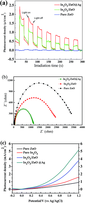 | ||
| Fig. 6 The photocurrent responses profiles (a), Nyquist plots of electrochemical impedance spectra (b), and linear sweep voltammetry (c) for pure ZnO, In2O3/ZnO, and In2O3/ZnO@Ag ternary composite. | ||
3.2 Photocatalytic activity and stability
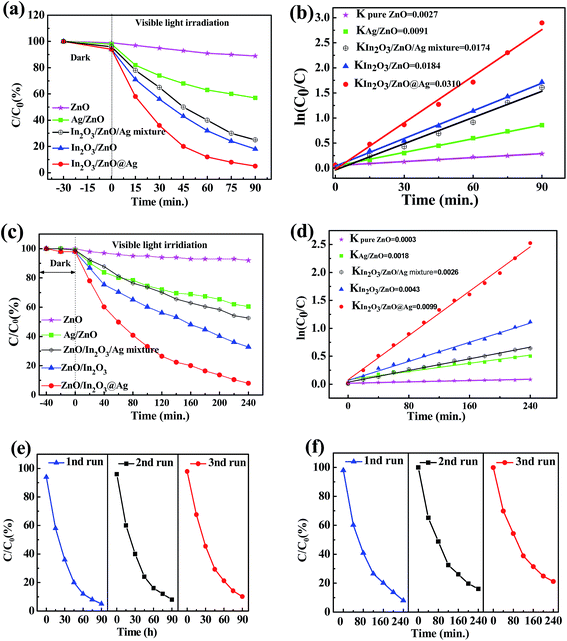
The photocatalytic activities of bare ZnO, In2O3/ZnO, and In2O3/ZnO@Ag ternary composite were evaluated in terms of the degradations of MO and 4-NP under visible light irradiation. As illustrated in Fig. 7, self-degradation of MO and 4-NP is negligible without the addition of photocatalysts; this indicates that these two types of organic dyes are photochemically stable. As shown in Fig. 7(a), In2O3/ZnO and In2O3/ZnO@Ag show evidently enhanced photocatalytic activity as compared to pure ZnO for the degradations of MO. For comparison, Ag/ZnO and In2O3/ZnO/Ag mixtures were used as reference catalysts. After visible light irradiation for 90 min, only 10% MO is degraded over ZnO, indicating that ZnO presents poor visible light photocatalytic activity for the degradation of MO, ascribed to the wide band gap of ZnO. The degradation rates of MO over Ag/ZnO and In2O3/ZnO reached 43% and 67%, respectively. Ag/ZnO present enhanced photocatalytic activity when compared with ZnO, which can be attributed to the Ag SPR effect.9,15 For In2O3/ZnO, the enhanced photocatalytic activity can be ascribed to the formation of a type II heterojunction between In2O3 and ZnO.10 Furthermore, when Ag is introduced into the In2O3/ZnO composites, the fabricated In2O3/ZnO@Ag ternary composites show highest degradation efficiency. The corresponding rate constants k determined for different catalysts are obtained by fitting the gradient of the graph of ln(C0/C) versus time, and the results are shown in Fig. 7(b). The obtained rate constants k are 0.0027 min−1, 0.0091 min−1, 0.0174 min−1, 0.0184 min−1, and 0.031 min−1 for ZnO, Ag/ZnO, In2O3/ZnO, In2O3/ZnO/Ag mixture, and In2O3/ZnO@Ag, respectively. The k value of In2O3/ZnO@Ag is about twice that of In2O3/ZnO, 3.5 times that of Ag/ZnO, and 11 times that of ZnO.Fig. 7(c) shows the photocatalytic activities of pure ZnO, ZnO/In2O3, and In2O3/ZnO@Ag ternary composites for the degradation of 4-NP. After visible light irradiation for 240 min, pure ZnO materials show very low degradation efficiencies for 4-NP; however, degradation efficiencies for 4-NP significantly increase to 40%, 44%, 68%, and 92% for Ag/ZnO, In2O3/ZnO/Ag mixture, ZnO/In2O3, and In2O3/ZnO@Ag, respectively. In2O3/ZnO@Ag shows the best catalytic effect for the degradation of 4-NP. The k values are determined to be 0.0003, 0.0018, 0.0028, 0.0043, and 0.0099 min−1 (as shown in Fig. 7(d)). The photocatalytic performance ranking of these composites for the degradation of MO and 4-NP is same as follows: In2O3/ZnO@Ag > ZnO/In2O3 > In2O3/ZnO/Ag mixture > Ag/ZnO > ZnO. This suggests that introduction of Ag into ZnO/In2O3 composites may improve the separation of photo-generated electron–hole pairs, which is beneficial to enhance the photocatalytic performance.
As the photo-stability of a photocatalyst is very important for its practical applications, cyclic photocatalytic degradation experiments were carried out to investigate the photo-stability of In2O3/ZnO@Ag. As displayed in Fig. 7(e and f), the degradation rates of MO and 4-NP show only a little decrease after three cycles. Excluding the loss of the photocatalyst in the cycling tests, In2O3/ZnO@Ag can be considered as a stable photocatalyst.
3.3 Proposed photocatalytic mechanism
As is well-known, it is important to investigate the active species in the photocatalytic process to better understand the mechanism of photocatalysis. The photocatalytic degradation of dyes mainly involves several active radical species such as hole (h+), superoxide anion radical (˙O2−), and hydroxyl radicals (˙OH).18,27 To distinguish the roles of the reactive species, a series of scavengers is employed during the photodegradation processes. Benzoquinone (BQ), ammonium oxalate (AO), and tert-butanol (t-BuOH) are used as scavengers for ˙O2−, photogenerated holes, and ˙OH in degradation of MO, respectively. As shown in Fig. 8, with 1 mmol of tert-butyl alcohol (t-BuOH) as an ˙OH scavenger added to the solution, the degradation rate of MO over the In2O3/ZnO@Ag ternary composites sample has no obvious decrease, implying that ˙OH radical species plays a relatively minor role in the reaction system. However, photocatalytic activity of the In2O3/ZnO@Ag ternary composite is greatly suppressed by the addition of BQ or AO, suggesting that both photo-generated ˙O2− and holes are the main oxidative species and play crucial roles in the degradation process of MO. To further confirm the role of ˙O2− radical species, a N2 purging experiment was conducted and its results were compared with those obtained under air-equilibrated conditions. The photocatalytic efficiency of the In2O3/ZnO@Ag ternary composite is obviously suppressed under a N2 atmosphere (N2 as the O2 scavenger). The results imply that dissolved oxygen can act as an electron scavenger to give ˙O2− radical species during the photocatalytic reaction. Consequently, it can be further confirmed that the photocatalytic degradation of MO over the as-prepared ZnO/In2O3@Ag composite is mainly governed by ˙O2− and h+ rather than ˙OH under visible light irradiation.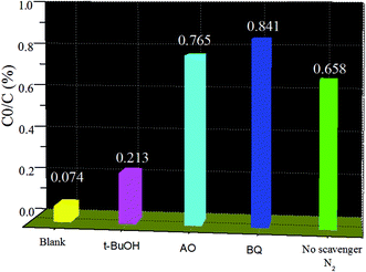 | ||
| Fig. 8 Trapping experiment of active species during the photocatalytic degradation of MO over In2O3/ZnO@Ag under visible light irradiation. | ||
Based on the abovementioned results, a possible mechanism is put forward to explain the significantly enhanced photocatalytic activity over the In2O3/ZnO@Ag photocatalyst. As reported in previous studies, the work function of ZnO and In2O3 is 5.3 eV, 5.0 eV, whereas the work function of Ag is about 4.7 eV.49–51 After contact of In2O3, ZnO, and Ag, the Fermi energy level of ZnO becomes lower than that of In2O3 and Ag, and the electron transfers from In2O3 and Ag with higher Fermi level to ZnO until the united new Fermi energy level (Ef) is formed (Fig. 9(a)).26,52
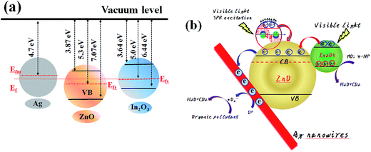 | ||
| Fig. 9 Schematic showing the energy band structure (a) and electron–hole pair separation in the In2O3/ZnO@Ag composites (b). | ||
For the In2O3/ZnO@Ag system, the highest photocatalytic efficiency can be attributed to the good interface charge transfer process in the In2O3/ZnO@Ag heterojunction composites and the high crystallinity of ZnO, In2O3 and Ag; a possible schematic is presented in Fig. 9(b). It is well known that ZnO and In2O3 are n-type semiconductors and have staggered band offsets. Hence, a type II heterojunction will be formed between In2O3 and ZnO after contact. When In2O3/ZnO@Ag is irradiated by visible-light, the VB electrons of the In2O3 can be excited and migrate to the CB, leaving holes on the VB; the excited electrons will then transfer from the CB of the In2O3 to the CB of ZnO. Because the energy level of the CB for semiconductor ZnO is higher than the newly formed Fermi energy level Ef, subsequently, the electrons in the CB of ZnO then can further transfer to Ag. Therefore, Ag nanowires served as a terminal electron acceptor, thus prolonging the photogenerated electrons lifetime and facilitating the charge separation in the whole photocatalytic system. The high crystallinity and intimate interface contact between In2O3 and ZnO benefits the separation of photo-excited electrons and holes, hence enhancing the photocatalytic activity of the In2O3/ZnO@Ag composites.53,54 On the other hand, the SPR effect introduced by the Ag nanoparticles may also play a role in enhanced photocatalytic activities. Surface plasmon excitations are generated and partially converted into energetic electrons on the surface of Ag nanoparticles through optical transitions under visible-light irradiation.34,55 The energetic electrons are able to overcome the Schottky barrier at the interface of Ag–ZnO and transfer from Ag to the CB of ZnO due to its strong electron oscillating collectively upon SPR excitation.56,57
Subsequently, electron acceptors, such as adsorbed O2, can easily trap photoelectrons to yield superoxide radical anion (˙O2−) species. Degradation of organic contaminant subsequently takes place through ˙O2− radicals attacking the organic molecules. Moreover, the photo-generated holes in the valance band of In2O3 would transfer to the photocatalyst surface and directly oxidize the organic pollutants, resulting in obviously improved photocatalytic activity.58,59
4. Conclusions
In summary, an In2O3/ZnO@Ag ternary photocatalyst was successfully synthesized by a co-precipitation route. SEM investigation reveals that Ag nanomaterials are encapsulated by In2O3/ZnO, where large quantities of In2O3 NPs are inlaid in the ZnO shell. Compared to those of pure ZnO and In2O3/ZnO, the photo responsive range is extended and PL emission intensity is significantly decreased for In2O3/ZnO@Ag ternary composite; and the ternary photocatalyst In2O3/ZnO@Ag composite shows the highest visible-light photocatalytic activity for the degradation of MO and 4-NP. The photocatalytic mechanism analysis reveals that the introduction of Ag plays an essential role in improving the photocatalytic activity, owing to the enlarged light absorption region and strong localization of plasmonic near-field effects; moreover, In2O3 provides a broad light absorption region and effectively enhances electron transfer at interfaces by the formation of a type II heterojunction. Therefore, there is a synergetic effect among ZnO, In2O3, and Ag nanowires in the investigated composites, which is favorable for the visible light photocatalytic activity of the In2O3/ZnO@Ag composites.Acknowledgements
This work was supported by the National Natural Science Foundation of China (No. 51502081) and Basic and Frontier Research Programs of Henan Province (No. 152300410088).References
- X. Li, J. G. Yu and M. Jaroniec, Chem. Soc. Rev., 2016, 45, 2603–2636 RSC.
- L. Mohapatra and K. M. Parida, J. Mater. Chem. A, 2016, 4, 10744–10766 CAS.
- H. Tong, S. X. Ouyang, Y. P. Bi, N. Umezawa, M. Oshikiri and J. H. Ye, Adv. Mater., 2012, 24, 229–251 CrossRef CAS PubMed.
- R. R. Wang, K. C. Pan, D. D. Han, J. J. Jiang, C. X. Xiang, Z. G. Huang, L. Zhang and X. Xiang, ChemSusChem, 2016, 9, 2470–2479 CrossRef CAS PubMed.
- H. J. Ren, P. Koshy, W. F. Chen, S. H. Qi and C. C. Sorrell, J. Hazard. Mater., 2017, 325, 340–366 CrossRef CAS PubMed.
- S. Martha, P. C. Sahoo and K. M. Parida, RSC Adv., 2015, 5, 61535–61553 RSC.
- F. X. Xiao, S. F. Hung, J. W. Miao, H. Y. Wang, H. B. Yang and B. Liu, Small, 2015, 11, 554–567 CrossRef CAS PubMed.
- Y. F. Xu, C. Zhang, L. X. Zhang, X. H. Zhang, H. L. Yao and J. L. Shi, Energy Environ. Sci., 2016, 9, 2410–2417 CAS.
- H. Abdullah, D. H. Kuo, Y. R. Kuo, F. A. Yu and K. B. Cheng, J. Phys. Chem. C, 2016, 120, 7144–7154 CAS.
- W. N. Xing, C. M. Li, G. Chen, Z. G. Han, Y. S. Zhou, Y. D. Hu and Q. Q. Meng, Appl. Catal., B, 2017, 203, 65–71 CrossRef CAS.
- S. Bai, W. Y. Jiang, Z. Q. Li and Y. J. Xiong, ChemNanoMat, 2015, 1, 223–239 CrossRef CAS.
- M. L. Huang, S. X. Weng, B. Wang, J. Hu, X. Z. Fu and P. Liu, J. Phys. Chem. C, 2014, 118, 25434–25440 CAS.
- H. R. Liu, G. X. Shao, J. F. Zhao, Z. X. Zhang, Y. Zhang, J. Liang, X. G. Liu, H. S. Jia and B. S. Xu, J. Phys. Chem. C, 2012, 116, 16182–16190 CAS.
- S. Kuriakose, B. Satpati and S. Mohapatra, Phys. Chem. Chem. Phys., 2015, 17, 25172–25181 RSC.
- X. L. Ma, H. Li, T. Y. Liu, S. S. Du, Q. P. Qiang, Y. H. Wang, S. Yin and T. Sato, Appl. Catal., B, 2017, 201, 348–358 CrossRef CAS.
- D. Y. Hong, W. L. Zang, X. Guo, Y. M. Fu, H. X. He, J. Sun, L. L. Xing, B. D. Liu and X. Y. Xue, ACS Appl. Mater. Interfaces, 2016, 8, 21302–21314 CAS.
- J. H. Han, Z. F. Liu, K. Y. Guo, B. Wang, X. Q. Zhang and T. T. Hong, Appl. Catal., B, 2015, 163, 179–188 CrossRef CAS.
- C. J. Dong, X. Liu, B. Q. Han, S. J. Deng, X. C. Xiao and Y. D. Wang, Sens. Actuators, B, 2016, 224, 193–200 CrossRef CAS.
- S. Martha, K. H. Reddy and K. M. Parida, J. Mater. Chem. A, 2014, 2, 3621–3631 CAS.
- L. L. Wang, J. Gao, B. F. Wu, K. Kan, S. Xu, Y. Xie, L. Li and K. Y. Shi, ACS Appl. Mater. Interfaces, 2015, 7, 27152–27159 CAS.
- S. Chabri, A. Dhara, B. Show, D. Adak, A. Sinha and N. Mukherjee, Catal. Sci. Technol., 2016, 6, 3238–3252 CAS.
- D. Kandi, S. Martha, A. Thirumurugan and K. M. Parida, J. Phys. Chem. C, 2017, 121, 4834–4849 CAS.
- S. Senapati and K. K. Nanda, ACS Appl. Mater. Interfaces, 2015, 7, 23481–23488 CAS.
- S. Patnaik, S. Martha, G. Madras and K. M. Parida, Phys. Chem. Chem. Phys., 2016, 18, 28502–28514 RSC.
- S. K. Wu, X. P. Shen, G. X. Zhu, H. Zhou, Z. Y. Ji, K. M. Chen and A. H. Yuan, Appl. Catal., B, 2016, 184, 328–336 CrossRef CAS.
- W. Q. Fan, X. Q. Yu, H. C. Lu, H. Y. Bai, C. Zhang and W. D. Shi, Appl. Catal., B, 2016, 181, 7–15 CrossRef CAS.
- Y. Q. Tang, R. R. Wang, Y. Yang, D. P. Yan and X. Xiang, ACS Appl. Mater. Interfaces, 2016, 8, 19446–19455 CAS.
- W. L. Zhang, Y. G. Sun, Z. Y. Xiao, W. Y. Li, B. Li, X. J. Huang, X. J. Liu and J. Q. Hu, J. Mater. Chem. A, 2015, 3, 7304–7313 CAS.
- C. Z. Luo, D. L. Li, W. H. Wu, C. Z. Yu, W. P. Li and C. X. Pan, Appl. Catal., B, 2015, 166, 217–223 CrossRef.
- G. Zhou, X. Xu, T. Ding, B. Feng, Z. J. Bao and J. G. Hu, ACS Appl. Mater. Interfaces, 2015, 7, 26819–26827 CAS.
- C. L. Tang, H. W. Bai, L. Liu, X. L. Zan, P. Gao, D. D. Sun and W. Yan, Appl. Catal., B, 2016, 196, 57–67 CrossRef CAS.
- J. He, D. W. Shao, L. C. Zheng, L. J. Zheng, D. Q. Feng, J. P. Xu, X. H. Zhang, W. C. Wang, W. H. Wang, F. Lua, H. Dong, Y. H. Cheng, H. Liu and R. K. Zheng, Appl. Catal., B, 2017, 203, 917–926 CrossRef CAS.
- S. Y. Bao, Q. F. Wu, S. Z. Chang, B. Z. Tian and J. L. Zhang, Catal. Sci. Technol., 2017, 7, 124–132 CAS.
- Y. Y. Bu, Z. Y. Chen and C. J. Sun, Appl. Catal., B, 2015, 179, 363–371 CrossRef CAS.
- Z. Y. Lu, X. X. Zhao, Z. Zhu, M. S. Song, N. L. Gao, Y. S. Wang, Z. F. Ma, W. D. Shi, Y. S. Yan and H. J. Dong, Catal. Sci. Technol., 2016, 6, 6513–6524 CAS.
- H. B. Kim, D. W. Jeong and D. J. Jang, CrystEngComm, 2016, 18, 898–906 RSC.
- F. Zhang, X. Y. Li, Q. D. Zhao and A. C. Chen, J. Phys. Chem. C, 2016, 120, 19113–19123 CAS.
- L. L. Wang, J. Gao, B. F. Wu, K. Kan, S. Xu, Y. Xie, L. Li and K. Y. Shi, ACS Appl. Mater. Interfaces, 2015, 7, 27152–27159 CAS.
- A. H. Mady, M. L. Baynosa, D. Tuma and J. J. Shim, Appl. Catal., B, 2017, 203, 416–427 CrossRef CAS.
- A. Meng, J. Xing, Z. J. Li, Q. Wei and Q. D. Li, J. Mol. Catal. A: Chem., 2016, 411, 290–298 CrossRef CAS.
- H. R. Liu, G. X. Shao, J. F. Zhao, Z. X. Zhang, Y. Zhang, J. Liang, X. G. Liu, H. S. Jia and B. S. Xu, J. Phys. Chem. C, 2012, 116, 16182–16190 CAS.
- A. H. Mady, M. L. Baynosa, D. Tuma and J. J. Shim, Appl. Catal., B, 2017, 203, 416–427 CrossRef CAS.
- B. Chai, T. Y. Peng, J. Mao, K. Li and L. Zan, Phys. Chem. Chem. Phys., 2012, 14, 16745–16752 RSC.
- K. C. Christoforidisa, T. Montini, E. Bontempi, S. Zafeiratosc, J. J. D. Jaénd and P. Fornasieroa, Appl. Catal., B, 2016, 187, 171–180 CrossRef.
- X. Yang, H. Li, W. Zhang, M. X. Sun, L. Q. Li, N. Xu, J. D. Wu and J. Sun, ACS Appl. Mater. Interfaces, 2017, 9, 658–667 CAS.
- W. H. He, R. R. Wang, L. Zhang, J. Zhu, X. Xiang and F. Li, J. Mater. Chem. A, 2015, 3, 17977–17982 CAS.
- Q. Z. Wanga, J. J. He, Y. B. Shi, S. L. Zhang, T. J. Niu, H. D. She, Y. P. Bi and Z. Q. Lei, Appl. Catal., B, 2017, 214, 158–167 CrossRef.
- L. Yang, W. H. Wang, H. Zhang, S. H. Wang, M. Zhang, G. He, J. G. Lv, K. R. Zhu and Z. Q. Sun, Sol. Energy Mater. Sol. Cells, 2017, 165, 27–35 CrossRef CAS.
- H. F. Wang, X. Q. Liu and S. Han, CrystEngComm, 2016, 18, 1933–1943 RSC.
- S. Zhang, P. Song, J. Li, J. Zhang, Z. X. Yang and Q. Wang, Sens. Actuators, B, 2017, 241, 1130–1138 CrossRef CAS.
- X. Xiang, L. S. Xie, Z. W. Li and F. Li, Chem. Eng. J., 2013, 221, 222–229 CrossRef CAS.
- R. Xu, H. H. Li, W. W. Zhang, Z. P. Yang, G. W. Liu, Z. W. Xu, H. C. Shao and G. J. Qiao, Phys. Chem. Chem. Phys., 2016, 18, 2710–2717 RSC.
- W. K. Jo and T. S. Natarajan, ACS Appl. Mater. Interfaces, 2015, 7, 17138–17154 CAS.
- Y. W. Yang, W. X. Que, X. Y. Zhang, Y. L. Xing, X. T. Yin and Y. P. Du, J. Hazard. Mater., 2016, 317, 430–439 CrossRef CAS PubMed.
- Y. M. Liang, N. Guo, L. L. Li, R. Q. Li, G. J. Ji and S. Gan, New J. Chem., 2016, 40, 1587–1594 RSC.
- W. W. He, H. K. Kim, W. G. Wamer, D. Melka, J. H. Callahan and J. J. Yin, J. Am. Chem. Soc., 2014, 136, 750–757 CrossRef CAS PubMed.
- W. Q. Fan, C. Chen, H. Bai, B. F. Luo, H. Q. Shen and W. D. Shi, Appl. Catal., B, 2016, 195, 9–15 CrossRef CAS.
- W. L. Yu, D. F. Xu and T. Y. Peng, J. Mater. Chem. A, 2015, 3, 19936–19947 CAS.
- F. Guo, W. L. Shi, W. S. Guan, H. Huang and Y. Liu, Sep. Purif. Technol., 2017, 173, 295–303 CrossRef CAS.
| This journal is © The Royal Society of Chemistry 2017 |

