
 Open Access Article
 This Open Access Article is licensed under a
 Creative Commons Attribution 3.0 Unported Licence
Photothermal catalytic activity of combustion synthesized LaCoxFe1−xO3 (0 ≤ x ≤ 1) perovskite for CO2 reduction with H2O to CH4 and CH3OH†
Lijuan Xua,
Minh Ngoc Hac,
Qiangsheng Guob,
Lichao Wanga,
Yanan Rena,
Na Sha*b and
Zhe Zhao*ad
aSchool of Materials Science and Engineering, Shanghai Institute of Technology, Shanghai 201418, China. E-mail: zhezhao@kth.se
bSchool of Chemical and Environmental Engineering, Shanghai Institute of Technology, Shanghai 201418, China. E-mail: shana8033@163.com
cFaculty of Chemistry, Hanoi University of Science, Vietnam National University, Hanoi 10000, Vietnam
dDepartment of Materials Science and Engineering, KTH Royal Institute of Technology, SE-100 44 Stockholm, Sweden
First published on 27th September 2017
Abstract
A range of LaCoxFe1−xO3 perovskites with different Co-doping at the B-site were successfully synthesized via a sol–gel combustion route. Phase pure samples were obtained by calcination at 700 °C for 2 h. The morphology, crystal structure, surface area, band structures, oxygen vacancies and catalytic properties of each analog were characterized in detail. The band structures and oxygen vacancies of the catalysts were changed by adjusting the dopant concentration. The catalytic performance of the LaCoxFe1−xO3 materials was characterized using water as a hydrogen source in the production of CH4 and CH3OH from CO2. Under photothermal conditions, 350 °C with a visible light source equipped with 420 nm cut filter, it was found that x value will influence the total yield and the solar to CH4 and CH3OH energy conversion efficiency significantly. For x = 0.6 compound, the production of CH4 and CH3OH evolution can reach 437.28 and 13.75 μmol g−1 in 6 h, which were 3.2 and 4.0 times that of LaFeO3 under the same condition. The overall solar-to-methane efficiency and solar-to-methanol efficiency for LaCo0.6Fe0.4O3 were 0.603%, 0.019% and for LaFeO3 were 0.191%, 0.005% in the photothermal mode, respectively. The results show that the band gap energy is correlated with the photothermal activity and the LaCo0.6Fe0.4O3 has the position of the CB and VB more suitable for CO2 reduction. The CB and VB value of LaCo0.6Fe0.4O3 were −0.258 and +1.422 V and CO2 (−0.24 V for CB) can be reduced to methane under the conditions.
Introduction
Global industrialization leading to rising energy demand has resulted in a substantial increase in CO2 emissions worldwide.1 It is now broadly accepted that this increase is having a significant impact on the environment.2,3 Finding a solution to this problem has become a global research focus with many investigators using conventional physical capture and storage techniques to control produced CO2.4,5 However, there are numerous drawbacks to this approach, such as low capture efficiency, high process cost, high energy consumption and potential environmental hazards.6 Compared with this traditional physical method, chemical utilization is more economically favorable and to convert CO2 into hydrocarbon fuels was quite attractive.7 A more environmentally robust solution is to convert CO2 into raw chemical materials using solar energy.8,9 This approach has the dual advantages of addressing the CO2 emissions from factories, cars and other sources while providing by-products that are raw materials for future use as fuels.10Photocatalysis is an emerging field of catalysis that has developed over the last 20 years. Given the environmental impact of current energy consumption practices, photocatalysis has the potential to provide a promising green and efficient alternative. A number of different semiconductor materials are being used as photocatalysts.11–14 The electrochemical splitting of water using TiO2 as a catalyst, published by Fujishima and Honda in 1972, is regarded as the beginning of photocatalysis.15 TiO2 has since been studied extensively owing to its efficiency, stability, and low cost. But its wide band gap requires the use of ultra-violet energy to initiate the reactions, resulting in its photocatalysis in the existence of some limitations. Photocatalytic reduction of CO2 is a viable method for converting CO2 into chemical raw materials (carbon compounds such as inorganic carbonates, methane and methanol) and has considerable significance in carbon recycling.16,17 Since Hiroshi reported the photocatalytic reduction of CO2 into organic compounds over semiconductor particles suspended in water,18 a new method combining photo, thermal, electrical and chemical processes on the basis of photocatalysis has been developed by researchers. This approach improved the conversion rate for the reduction of CO2 to CO, C and O2 and H2O to H2 and O2, compared with conversion rates for photo or thermal catalysis alone.19,20
Perovskites, which have the general formula ABO3, are materials of potential owing to their stability, magnetism, crystal structure, electrical conductivity and piezoelectric properties. These advantages give rise to applications in magnetoresistance devices,21–23 as solid electrolytes,24 as transducers25–28 and in catalysis.29–32 Many perovskite materials have good response in the ultraviolet region. Among them, transition metal based LaFeO3 is a visible light active material, which is suitable for the use of renewable solar energy as a light source to excite electrons for the CO2 reduction. LaFeO3 has shown great promising in terms of catalytic activity in the photocatalytic decomposition of water and the degradation of organic pollutants.34–38 The efficiency of a material in harnessing solar energy is related to its band gap, which determines the range of the incident photon band that can be absorbed and can further affects the photocatalytic activity.39 For the typical ABO3 perovskite, both A- and B-site can be substituted to modify the local electronic structure, band gap and oxygen vacancy concentration in order to realize versatile properties.33,40 In some case, the band gap of LaFeO3 can even be modified through variation of the calcination temperature.41 In this study, we try to modify the band gap and the relative position of the valence band and the conduction band through partial substitution of Fe by Co at the B-site in LaFeO3 to investigate photothermal catalytic efficiency of materials.
In a typical experiment, the catalysts in accordance with formula LaCoxFe1−xO3 perovskites were synthesized via a sol–gel combustion route and were calcined in air for 2 h at different temperatures between 500 and 900 °C. Then the synthesized samples were characterized using a range of scientific researching instruments (S1†). The whole experiment have been carried out in a catalytic reactor as show in Fig. 1. The reaction was in a gas tight circulation system, the volume of the reaction system was about 130 mL. The evaluation of catalytic activity was performed at 350 °C and used a 300 W Xe lamp with a UV-light filter (λ > 420 nm). Taking a sample every hour and qualitatively analyzed by GS-Tek (Echromtek A90) and quantitatively analyzed by gas chromatograph equipped with a flame ionization detector (S1†). Finally, the catalytic performance of LaCoxFe1−xO3 (x = 0, 0.2, 0.4, 0.6, 0.8, 1) are reported, with the photothermal reduction of CO2 with H2O vapor to CH4 used to probe catalytic activity. The influence of Co content on the perovskite band gap, the CB and VB positions, oxygen vacancies and resulting photothermal activity for the CO2 reduction are revealed in detail.
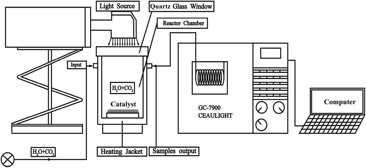 | ||
| Fig. 1 Photothermal catalytic reactor for CO2 reduction study. | ||
Results and discussion
Impurity phases within a crystal structure can have a substantial effect on the mechanical and electrical properties of a material. The XRD patterns of LaCo0.4Fe0.6O3 nanoparticles prepared at different calcination temperatures are shown in Fig. 2a. Through comparison with the characteristic peaks of the perovskite LaFeO3 (Fig. 2b), we conclude that the Co-doped samples have perovskite structures and contain no noticeable impurities.41 The diffraction peaks display an increase in intensity and narrowing in width with increasing calcination temperature, indicating that the perovskite crystallinity is affected by temperature. For the samples calcined at 500 and 600 °C, the LaCo0.4Fe0.6O3 nanoparticles, which belong to the Pm![[3 with combining macron]](https://www.rsc.org/images/entities/char_0033_0304.gif) m space group, have a cubic perovskite structure. The a values of the perovskites calcined at 500 and 600 °C were 3.9065 and 3.8912, respectively.
m space group, have a cubic perovskite structure. The a values of the perovskites calcined at 500 and 600 °C were 3.9065 and 3.8912, respectively.
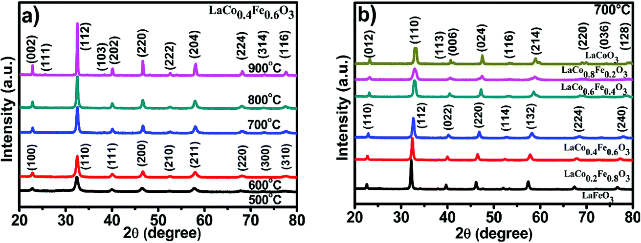 | ||
| Fig. 2 (a) XRD of LaCo0.4Fe0.6O3 nanoparticles at different temperature, (b) LaCoxFe1−xO3 photocatalyst at different Co-doping at 700 °C for 2 h. | ||
The diffraction peaks for samples calcined at 700, 800 and 900 °C suggest that these samples exhibit orthorhombic crystal systems with an ABO3 type perovskite structure (JCPDS card no. 01-081-2301), which belong to the Pnma space group. The crystallite sizes determined by the Scherrer equation are 73.85, 34.73, 24.67, 31.59 and 59.54 nm for the samples calcined at 500, 600, 700, 800 and 900 °C, respectively. The small crystallite sizes favored the surface reaction kinetic and electrical transport properties of the catalysts. Thus calcination temperature of 700 °C was chosen for all samples in the subsequent experiments in order to promise both small crystallite size and reasonably good crystallinity.
The XRD patterns of LaCoxFe1−xO3 (x = 0, 0.2, 0.4, 0.6, 0.8 and 1) nanoparticles prepared using the sol–gel combustion method with calcination at 700 °C for 2 h, are shown in Fig. 2b. Analysis of the characteristic peaks revealed no significant impurity phases. As the partial substitution of Fe by Co increases, we see that the peak intensity decreases and some of the peaks become split, the diffraction peaks shift regularly to the right, because of the greater strength of Fe–O bonding compared with Co–O bonding.23 Additionally it was observed that the perovskite structure is orthorhombic when the Co-doping level is 0, 0.2 or 0.4, however the structures are trigonal for crystals with Co-doping from 0.6 to 1. This suggests that Co-doping changes the lattice structure and x = 0.4–0.6 might be the region that two phases co-existed simultaneously, even we can't see that clearly from the XRD patterns. In addition, the crystallite size determined by the Scherrer equation can be also affected by the Co concentration in LaCoxFe1−xO3 as shown in Table 1.
| Samples (x) | Crystal system | 2-Theta (degree) | d(112) (nm) | Unit cell a, b, c (nm) | Crystallite size (nm) |
|---|---|---|---|---|---|
| 0.0 | Orthorhombic | 32.1818 | 0.277923 | 5.5601, 5.5651, 7.8562 | 32.7808 |
| 0.2 | 32.3892 | 0.276191 | 5.5171, 5.5201, 7.8184 | 26.8103 | |
| 0.4 | 32.5459 | 0.274897 | 5.5022, 5.5410, 7.7713 | 24.6748 |
| Samples (x) | Crystal system | 2-Theta (degree) | d(110) (nm) | Unit cell a = b, c (nm) | Crystallite size (nm) |
|---|---|---|---|---|---|
| 0.6 | Trigonal | 32.7522 | 0.273212 | 5.4610, 13.116 | 20.6059 |
| 0.8 | 32.8838 | 0.272149 | 5.4378, 13.164 | 56.8321 | |
| 1.0 | 32.8977 | 0.272037 | 5.4441, 13.112 | 48.7331 |
The specific surface areas and pore sizes of the LaCoxFe1−xO3 catalysts with the different substitutions (x) by using nitrogen adsorption–desorption isotherms at 77 K on a Micrometrics ASAP 2020 HD88 systems, are listed in Table 2. Except for the pure LaCoO3, the specific surface area of the samples changed within a limited range and thus the catalytic performance for samples of x = 0, 0.2, 0.4, 0.6 and 0.8 can be comparable if we believe that surface reaction dominated the most catalysis process.
| Ratio of Co doping (x) | Surface area (BET) m2 g−1 | Pore size (nm) |
|---|---|---|
| 0.0 | 9.2853 | 28.29821 |
| 0.2 | 7.3525 | 44.57917 |
| 0.4 | 8.4393 | 26.57818 |
| 0.6 | 9.7343 | 21.50945 |
| 0.8 | 5.1724 | 19.76648 |
| 1.0 | 2.7064 | 73.00958 |
The SEM images of LaCoxFe1−xO3 nanoparticles calcined at 700 °C are shown in Fig. 3a–f. As would be expected as a result of sol–gel combustion synthesis, it can be seen that the samples are porous materials. Comparing these micrographs with that of a pure LaFeO3 sample, reveals subtle differences in particle morphogenesis. Samples with a Co-doping of 0.2, 0.4 and 0.6 (Fig. 3b–d) exhibited increasingly rounded particles as the amount of cobalt increased, and showed greater porosity. When Co-doping is raised to 0.8 and 1, aggregation growth among the particles is clearly observed, which is expected to lead to a reduction in catalytic activity. The SEM images also reveal that the pores of the samples with Co-doping of 0.8 and 1 are isolated. This contrasts with the samples with lower doping ratios where the channels or pores are interconnected. Furthermore, their particle size is 100 nm. Consequently, we propose that the Co to Fe molar ratios of 0.2, 0.4 and 0.6 provide the most suitable morphology for good catalytic activity. Ratios above 0.6 promote crystallite growth, leading to larger particle size and lower BET surface area.
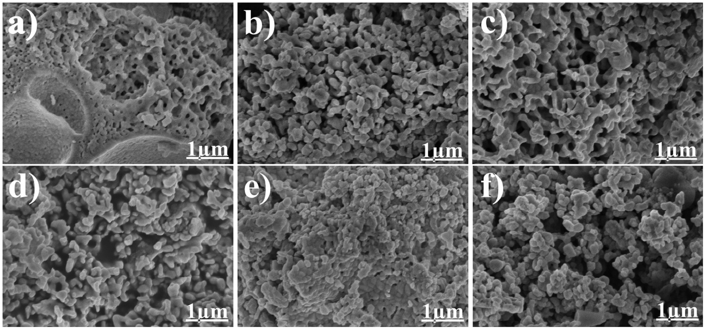 | ||
| Fig. 3 SEM images of LaCoxFe1−xO3 nanoparticle in different Co rate at (a) 0, (b) 0.2, (c) 0.4, (d) 0.6, (e) 0.8, (f) 1 at 700 °C for 2 h. | ||
More detailed information on LaCo0.6Fe0.4O3 nanoparticle morphology is presented in the TEM images in Fig. 4. The image in Fig. 4a shows that small nanoparticles with an average size of 50–100 nm form larger agglomerations composed of interconnected nanocrystal skeletons. These observations support the SEM findings. In addition, the TEM image in Fig. 4b shows clear lattice spacing (d values) for the LaCo0.6Fe0.4O3 nanoparticles. The interplanar (110) spacing of the LaCo0.6Fe0.4O3 nanoparticle was determined to be 0.27 nm by TEM. This corresponds with the (110) lattice spacing of the trigonal phase of the perovskite crystal structure from the XRD analysis, and is the same as XRD Rietveld structure refinement results for LaSrCoFeO6−δ. A Bruker-AXS 133 eV XFlash 4010 Detector associated with the SEM was used to measure the elemental composition of the LaCo0.6Fe0.4O3 as well as the nature of the distribution. From the EDS spectrum and the elemental mapping images in Fig. 4c, it can be seen that La, Fe, Co and O dominate the composition of LaCo0.6Fe0.4O3. These data support the uniform distribution of La, Fe, Co and O within the LaCo0.6Fe0.4O3 catalyst.
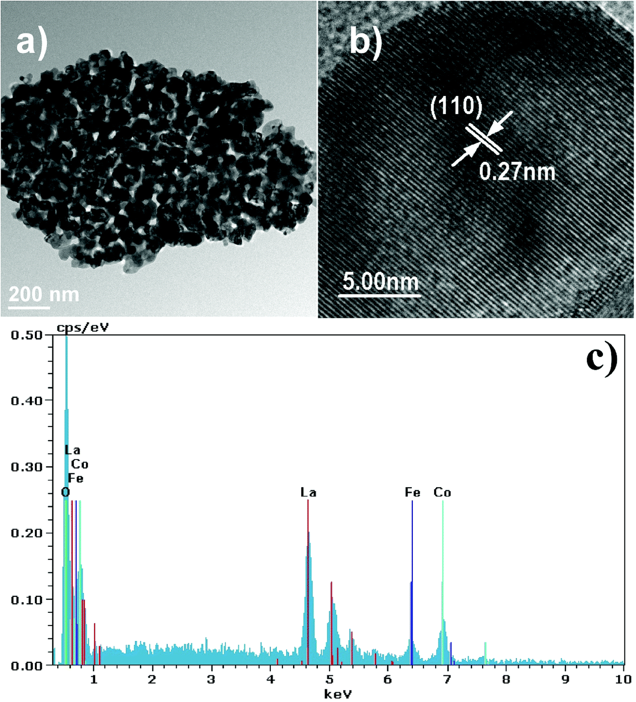 | ||
| Fig. 4 (a and b) TEM images and (c) EDS images of LaCo0.6Fe0.4O3−δ prepared at 700 °C for 2 h. | ||
The chemical state and surface species of the LaCoxFe1−xO3 catalysts were established by XPS analysis as shown in Fig. 5. The survey spectra (Fig. 5d) show peaks that are ascribed to La, Fe, Co, O and C. No peaks corresponding to other elements were observed. Table 3 reports the binding energies of the LaCoxFe1−xO3 perovskites, which provide evidence of the coexistence of at least two oxidation states for both the Co and Fe regions. Peak deconvolutions are shown in Fig. 5a and b. These observations agree with the literature.20,42,43 The oxidation states for both Fe and Co at the B-site were 2+ and 3+. The cobalt region shows the typical Co 2p pattern with Co 2p3/2 and Co 2p1/2 as shown in Fig. 5a, and also includes the respective shake-up satellite peaks. The Co 2p3/2 binding energies attributed to Co2+ and Co3+ were observed at 780 and 782 eV respectively. The Co 2p1/2 binding energy resolved into Co2+ and Co3+ contributions centered at 794 and 796 eV, respectively.43,44 The Fe 2p peak fitting of the LaCoxFe1−xO3 catalyst was performed according to the constraints of the Fe2+ and Fe3+ components and the respective shake-up satellites indicated by Liu.45 The high binding energy of the second component of iron in the table is attributed to Fe3+.42,46 The presence of doublets characteristic of Co 2p (Co3+) and Fe 2p (Fe3+) was observed for the samples, together with two bands corresponding to O 1s. These bands can be attributed to the lattice, surface and absorbed oxygen.47 The absorbed oxygen has been omitted from Table 4 with only the lattice and surface components used to calculate the relative amounts of the two types of oxygen. Interestingly, it has been reported that the surface oxygen component develops with the increase of oxygen vacancies,48 and the lattice component decreases with decreasing iron content, indicating an increase in the oxygen vacancies,44 which can lead to asymmetry of the main peak. It has also been reported that high-resolution O 1s XPS spectra indicate that the peak area of surface oxygen peaks obviously decreased with increasing catalytic reaction times.33 Besides, the O 1s signal of the LaCo0.6Fe0.4O3 perovskite was shows as well. The photothermal catalytic activities for CO2 conversion with H2O vapor to CH4 over LaCo0.6Fe0.4O3 catalysts showed that the catalytic activity depends on Co3+/Co2+, Fe3+/Fe2+ (detail in Table 3).
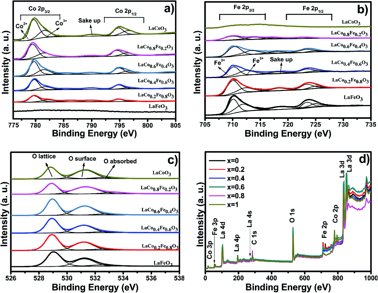 | ||
| Fig. 5 The XPS spectra of (a) Co 2p, (b) Fe 2p, (c) O 1s and (d) survey spectra of LaCoxFe1−xO3 (0, 0.2, 0.4, 0.6, 0.8, 1) catalyst prepared at 700 °C for 2 h. | ||
| Catalyst (x) | Co 2p (eV) | Fe 2p (eV) | ||
|---|---|---|---|---|
| Co 2p3/2(%) | Co 2p1/2(%) | Fe 2p3/2(%) | Fe 2p1/2(%) | |
| 0.0 | Co2+ | Co2+ | 710.03(66.22%) | 723.51(66.50%) |
| Co3+ | Co3+ | 711.85(33.78%) | 725.53(33.50%) | |
| 0.2 | 779.70(71.09%) | 794.66(72.34%) | 709.90(68.96%) | 723.41(70.01%) |
| 782.27(28.91%) | 796.05(27.66%) | 711.79(31.04%) | 725.64(29.99%) | |
| 0.4 | 779.67(69.20%) | 794.68(70.08%) | 710.13(70.92%) | 723.33(71.43%) |
| 780.69(30.80%) | 796.15(29.02%) | 712.46(29.08%) | 724.80(28.57%) | |
| 0.6 | 779.59(65.92%) | 794.59(66.32%) | 710.28(69.93%) | 723.34(70.45%) |
| 780.73(34.08%) | 796.15(29.02%) | 713.41(30.06%) | 724.64(29.55%) | |
| 0.8 | 779.24(66.66%) | 794.49(66.67%) | 709.66(62.32%) | 722.83(59.45%) |
| 780.25(33.34%) | 796.16(33.33%) | 711.72(37.68%) | 724.09(40.55%) | |
| 1 | 779.54(72.42%) | 794.75(70.34%) | Fe2+ | Fe2+ |
| 780.51(27.58%) | 796.37(29.66%) | Fe3+ | Fe3+ | |
| O 1s (eV) | 0.0 (%) | 0.2 (%) | 0.4 (%) | 0.6 (%) | 0.8 (%) | 1.0 (%) |
|---|---|---|---|---|---|---|
| Lattice oxygen | 54.34 | 52.95 | 51.49 | 46.49 | 46.17 | 45.97 |
| Surface oxygen | 38.17 | 40.28 | 41.53 | 47.84 | 46.58 | 45.34 |
| Absorbed oxygen | 7.49 | 6.77 | 6.98 | 5.67 | 7.25 | 8.69 |
| Surface/lattice | 0.70 | 0.76 | 0.81 | 1.03 | 1.01 | 0.99 |
The diffuse reflectance spectra of LaCoxFe1−xO3 perovskites prepared at different Co-doping molar ratios were measured and are shown in Fig. 6a. From the optical absorption spectra, we can see that the samples had a complete absorption edge. The results indicate that LaCoxFe1−xO3 nanoparticles are active in the visible light region, therefore, the properties of the samples can be tested using visible light driven methods.
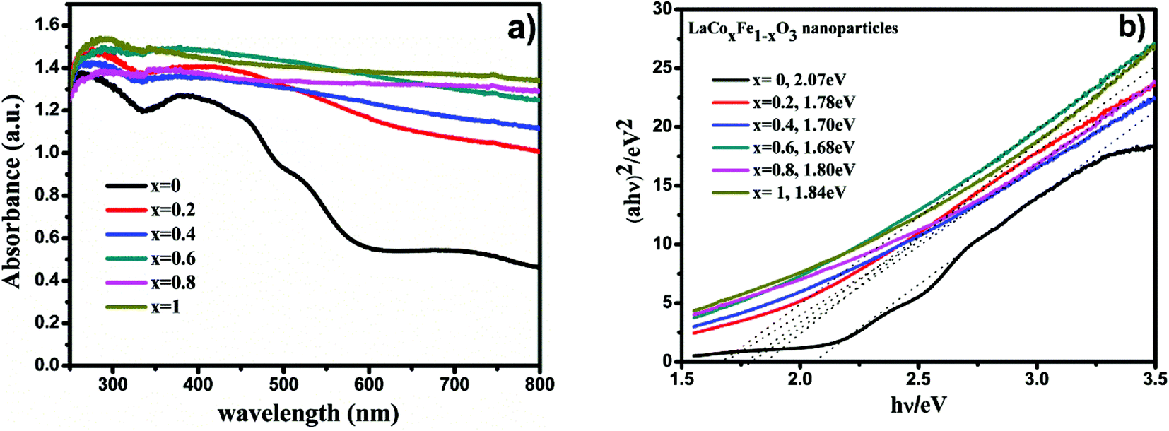 | ||
| Fig. 6 UV-Vis diffuse reflectance spectra of LaCoxFe1−xO3 nanoparticle in different Co rate (a), plots of (αhν)2 versus photon energy of LaCoxFe1−xO3 sample (b). | ||
To estimate the optical band gap (Eg) of the prepared samples, we used acquired data in the following equation:
| (αhν)m = K(hν − Eg) |
Table 5 shows the band gap energies determined for the LaCoxFe1−xO3 materials (x = 0, 0.2, 0.4, 0.6, 0.8, 1), which were found to be 2.07, 1.78, 1.70, 1.68, 1.80 and 1.84 eV, respectively. The lowest calculated band gap energy of 1.68 eV was obtained for x = 0.6. The highest energy band gap of 2.07 eV was calculated for the sample with no Co-doping. These data demonstrate the potential to control the optical response of LaFeO3 perovskites by controlling the band gap,49 and support the findings of subsequent photocatalytic performance tests. Even that Fe and Co both belongs to the typical transition metals, Fe3+ and Co3+ are different in either Eg electron number or the feasibility of reduction to 2+ valance state. So it is rational to expect that the mixing ration between Fe and Co should influence the band structure of LaCoxFe1−xO3.
| Co/Fe | 0.0 | 0.2 | 0.4 | 0.6 | 0.8 | 1.0 |
| Eg (eV) | 2.07 | 1.78 | 1.70 | 1.68 | 1.80 | 1.84 |
The correlation between the electronic band gap energy of a material and its photocatalytic activity is well understood. Narrower band gap facilitates more visible light absorption and so might increase the photocatalysis performance. In addition to determining band gap it is also important to study the conduction band (CB) and valence band (VB), and absolute energies in relation to the reduction and oxidation potentials. The potential of the CB edges (ECB) can be measured using the Mott–Schottky (MS) relationship. As can be seen in Fig. 7a–f, the typical n-type semiconductor characteristics of all samples were revealed by observing the positive slopes of the MS plots. The ECB of the samples was determined against a Ag/AgCl reference electrode in aqueous solution. The ECB of LaCoxFe1−xO3 nanoparticles with x values ranging from 0 to 1 were −0.314, −0.289, −0.263, −0.258, −0.276 and −0.305 V, respectively. The VB potential (EVB) values for the samples can be estimated approximately using the following equation: EVB = χ − Ee + 2Eg, ECB = EVB − Eg, where χ is the electronegativity of the atom, ECB is the CB edge potential, Ee is the energy on the hydrogen scale (4.5 eV) and Eg is the optical band gap of the semiconductor. Using the above results in combination with the band gap energies obtained from the diffuse reflectance spectra, the obtained values of EVB were 1.756, 1.491, 1.437, 1.422, 1.524, and 1.535 V, respectively. The EVB value for the sample with a Co-doping of 0.6 was found to be the lowest in the series (1.422 V). Photocatalytic performance of a material requires that the valence band electrons are excited to the conduction band into high-energy transition states, resulting in the formation of electron–hole pairs. A less positive VB position makes this excitation easier and enhances the redox potential of catalysts in photocatalytic processes. By considering the following half-equations:

| CO2 + 8e− + 8H+ → CH4 + 2H2O, (Eored = −0.24 V vs. NHE) |
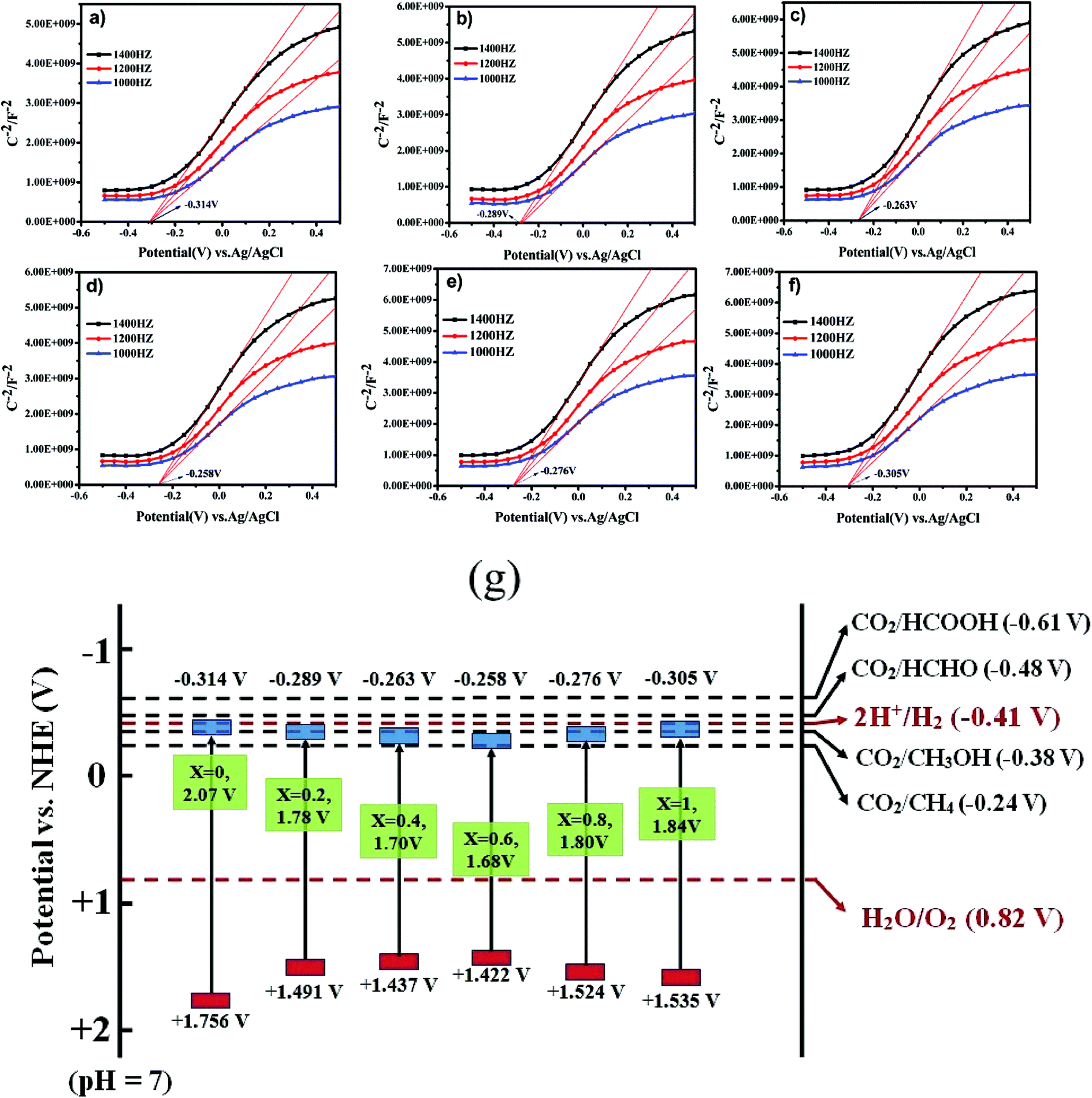 | ||
| Fig. 7 Mott–Schottky plots of LaCoxFe1−xO3 nanoparticle in different Co rate from 0 to 1 (a–f). A schematic illustration of the band structure of LaCoxFe1−xO3 nanoparticle (g). | ||
It is possible to deduce that the VB values for all samples are more positive than Eo(H2O/H+) and the CB values are more negative than Eo(CO2/CH4). These results indicate that the reactions could be initiated with photogenerated carriers (electrons and holes) in the irradiated LaCoxFe1−xO3 nanoparticles, leading to CH4 production through the adsorption of CO2 and H2O. All samples are black in color indicating a potential for efficient visible light absorption and higher photothermal catalytic efficiency.24 This is roughly consistent with the photothermal catalytic performance data reported in Fig. 8.
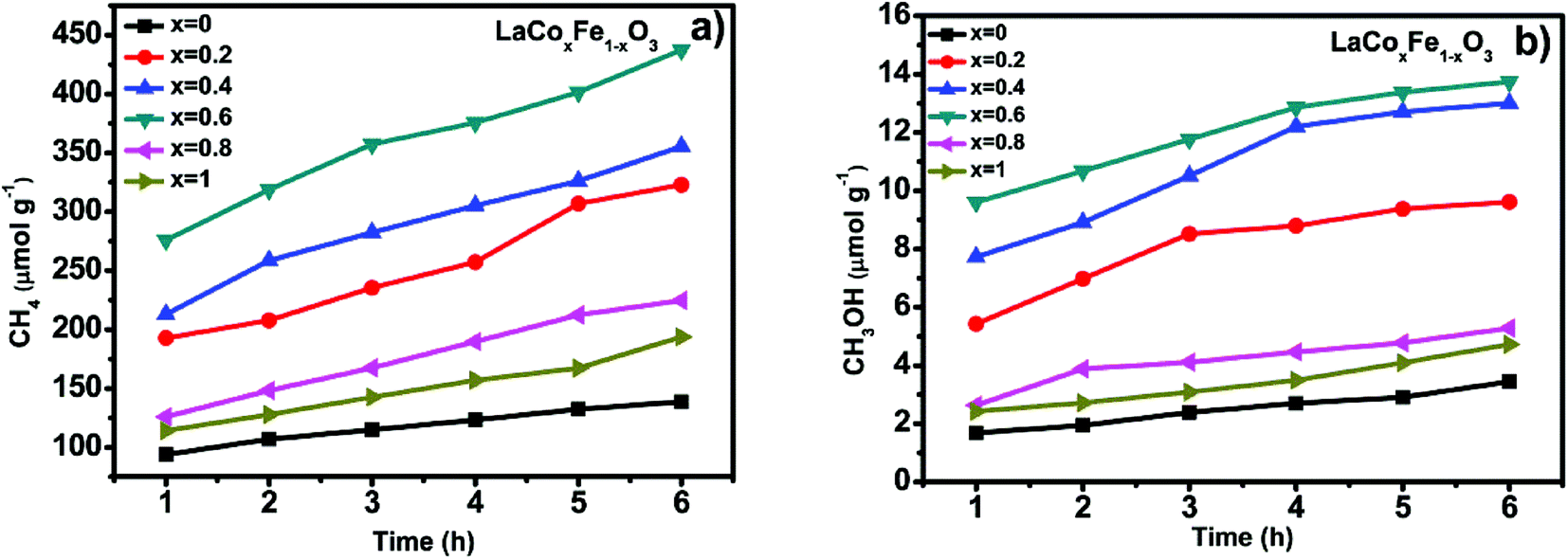 | ||
| Fig. 8 CH4 generation over the under visible light irradiation and heating condition at 350 °C (a) and CH3OH generation over the under visible light irradiation and heating condition at 350 °C (b). | ||
Fig. 8a and b show CH4 and CH3OH generation and photothermal catalytic activity at different Co-doping rates, evaluated under photothermal conditions, 350 °C and visible light irradiation for 6 h. Fig. 8a and b show a significant catalytic activity increase with Co-doping at the B-site, when compared with LaFeO3 perovskite. At the end of the 6 h reaction time, the methane yield for samples with different Co/Fe molar ratios was in the order of 0.6 > 0.4 > 0.2 > 0.8 > 1 > 0, a similar sequence was also observed for methanol yield. It is also clear from the data for all samples that photothermal catalytic activity increased over time. The production of CH4 and CH3OH from CO2 and H2O, under photothermal conditions after 6 h for x = 0, 0.2, 0.4, 0.6, 0.8 and 1, were 138.59, 322.84, 355.46, 437.28, 193.90, 224.70 μmol g−1 and 3.45, 9.61, 13.01, 13.75, 5.28, 4.72 μmol g−1 respectively (see Table 6). Looking more closely at the best performing Co-doped material based on the data described (x = 0.6), it is clear that CH4 and CH3OH generation over LaCo0.6Fe0.4O3 catalyst are 3.2 and 4.0 times of that of pure LaFeO3. It is also worth noting that two end compounds, pure LaFeO3 and LaCoO3, possess the lowest yield of CH4 and CH3OH. These results demonstrate that partial substitution of Fe with Co at the B-site leads to better catalytic performance under photothermal conditions.
| Sample (x) | The first hour production (μmol g−1) | Production after 6 h (μmol g−1) | Total yield (%) | ||
|---|---|---|---|---|---|
| Produce | CH4 | CH3OH | CH4 | CH3OH | CH4 + CH3OH |
| 0.0 | 93.86 | 1.68 | 138.59 | 3.45 | 2.44732 |
| 0.2 | 192.80 | 5.43 | 322.84 | 9.61 | 5.72843 |
| 0.4 | 213.01 | 7.72 | 355.46 | 13.01 | 6.34893 |
| 0.6 | 275.83 | 9.61 | 437.28 | 13.75 | 7.77147 |
| 0.8 | 114.27 | 2.63 | 193.90 | 5.28 | 3.96264 |
| 1.0 | 126.03 | 2.42 | 224.70 | 4.72 | 3.42235 |
Energy conversion efficiency of photothermal reduction of CO2 with H2O vapor to CH4 and CH3OH over LaCoxFe1−xO3 perovskites can be expressed more adequately by total yield (conversion rate of CO2 to CH4 and CH3OH) STM (solar-to-methane or methanol) efficiency (S2†). As shown in Table S2,† the best overall CO2 conversion rate can reach 7.77% for x = 0.6 LaCoxFe1−xO3. Considering the fact that it is not possible to avoid gas leakage in our reactor (only simple sealing implemented) at elevated temperature, it is rational to expect that a higher total yield can be expected if a high pressure reactor can be built in the future. The highest STM efficiency of CH4 and CH3OH for x = 0.6 LaCoxFe1−xO3 can reach 0.6% and 0.019% respectively. Unfortunately, there is not much reported data can be used to compare the performance of our catalyst without noble metal loaded. F. Saladin51 had reported an accumulated CH4 yield of 24 μmol g−1 at 200 °C after 6 h UV light irradiation with CO2 and H2O as raw material and Degussa P25 TiO2 as catalyst in a very similar photothermal catalysis study.
In conclusion, the catalytic activity determined for LaCoxFe1−xO3 nanoparticles is consistent with the various characterization results. More specifically we can speculate that the influencing factors on catalytic activity may be correlated to surface area, crystallite size, band gap and oxygen vacancies based on the following observations. First the greater the surface area, the greater the area for photon radiation and catalytic reaction sites. Second, the small pores size can improve their catalytic performance by increasing the adsorption efficiency of the reactants. However, the characterization results of the samples in these two aspects shows that there is no significant difference in our experiments. Furthermore, the smaller the crystallite size, the shorter the migration time of photoinduced charge carriers from the bulk to the surface, meaning that they have chance to reach to surface before recombination to improve the catalytic efficiency.38 Lastly, we focus on the specific effects of band structure and oxygen vacancies on photothermal activity. By adjusting the band structure of the material, the band gaps of the Co-doped samples became smaller and the positions of the CB and VB became more suitable for CO2 photo reduction. We reported that the minimum band gap is 1.68 eV when Co content is 0.6. This contributes to the effective separation process of electron–hole pairs and also helps to inhibit the recombination of photoinduced charge carriers. And oxygen vacancies can facilitate the separation of water and in the reaction process to improve the catalytic efficiency.19 Additionally, our observations may depend on the photo-thermal coupling effect which could have resulted from our experimental conditions which used simultaneous irradiating with visible light and heating. The combination of all of these factors can be regarded as favorable for photocatalytic reaction give the observed increase in the photocatalytic activity.
The reaction mechanism for the photothermal reduction of CO2 to CH4 with H2O vapor over catalyst samples is shown in Fig. 9. The catalytic process involves five steps (a)–(d): (a) the first is irradiation of the catalyst surface by a visible light source. This process requires a large catalyst surface area for exposure to radiation from the sun. Since LaCoxFe1−xO3 perovskite surfaces can adsorb CO2 and H2O molecules, the catalyst surface is vital for developing its role in the photocatalytic reduction of CO2. (b) An electron of the valence band absorbs energy from a photon greater than or equal to the band gap energy, and transitions to a high energy state in the conduction band, resulting in the formation of an electron–hole pair (carrier). Considering Fig. 7g and the reported data, we can conclude that the VB edge position of all LaCoxFe1−xO3 compounds is more negative than that needed for the production of CH4. It is therefore believed that methane can be mainly produced through photocatalytic reduction of CO2. However, the VB edge of all LaCoxFe1−xO3 compounds is not negative enough for the production of CH3OH through photocatalytic reduction process. So we have to point out that the production of small amount of CH3OH in our study might be the result of thermal catalysis, the reaction process can be referred to that described in ESI S3.† (c) Most of the carriers will recombine and the energy produced will disperse out in the form of thermal energy or photons. (d) At the same time, the carriers produced by electronic excitation migrate to the surface of the sample or reach the interface with further aid. Furthermore, the corresponding active sites of oxidation and reduction are formed. Finally, the carriers which have been photogenerated and transmitted to the surface of the catalyst react with CO2 and H2O molecules to obtain O2 and H+ and various hydrocarbons.50 In addition, methane, methanol and other hydrocarbons can be generated by interacting CO2 with H+ and electrons, which according to the reduction of force can accept different numbers of electrons. In summary, the photothermal catalytic activity of LaFeO3 was enhanced by Co-doping, which adjusted the band structure and reduced the band gap. These findings may be of importance for a variety of applications.
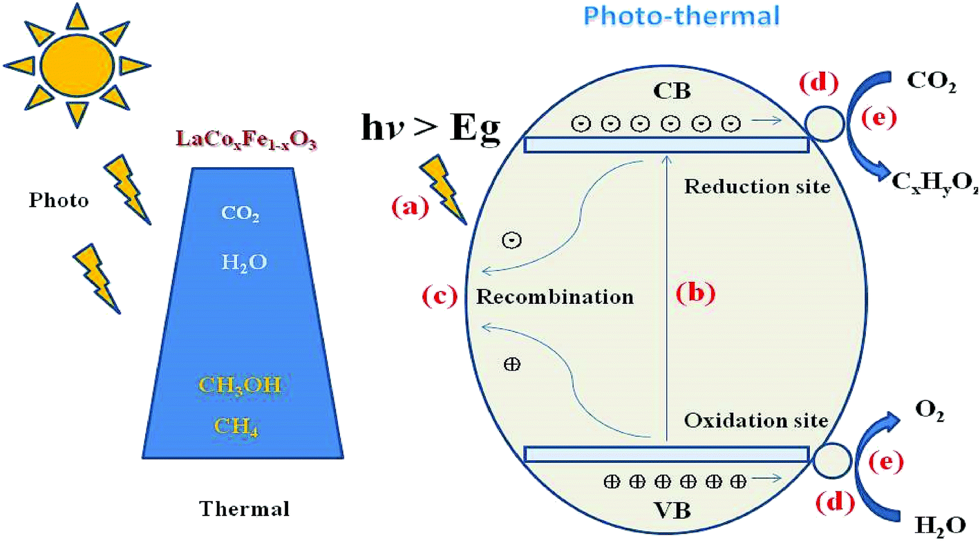 | ||
| Fig. 9 Schematic diagram of the combined photo- and thermal-catalytic reduction of CO2 with H2O vapor to CH4 in one system over LaCoxFe1−xO3 perovskites. | ||
Conclusions
We successfully synthesized LaCoxFe1−xO3 (x = 0, 0.2, 0.4, 0.6, 0.8, 1) nanoparticles using the sol–gel process by Co-doping to achieve different molar ratios at the B-site of the ABO3 style perovskite model. Their structure, phase components, morphology, surface area, and electronic structure were investigated using XRD, SEM, TEM, BET and UV-vis characterization methods, and their catalytic properties were investigated. Under photothermal reaction conditions, the Co-doped catalysts displayed better catalytic performance for the reduction of CO2 to CH4 (with H2O) than LaFeO3. It is well known that the electronic structure of a material can be influenced by doping with transition metal elements. In this study Co incorporation resulted in significant changes to the valence and conduction band positions, which reduced the band gap. The CH4 and CH3OH generation rates for the reduction of CO2 to CH4 (with H2O) using LaCo0.6Fe0.4O3 as the catalyst, were enhanced 3.2 and 4.0 times respectively compared with LaFeO3 under the same photothermal reaction conditions. This confirms that the partial substitution of Fe by Co at the B-site of LaFeO3 perovskite manifests in greater catalytic activity. Based on these findings, we believe that the high catalytic activity is associated with small crystallite size, large specific surface area, small porous size, small band gap and suitable valence and conduction band positions of the material. However, the most important is to adjust the valence band to the conduction better position to achieve optimization of the material band structure, all of which would improve the CO2 and H2O adsorption and reaction at the catalyst surface. These results may further promote the application of LaCoxFe1−xO3 in catalysis, environmental cleaning and solar fuel production.Conflicts of interest
There are no conflicts to declare.Notes and references
- C. C. Lo, C. H. Hung, C. S. Yuan and J. F. Wu, Sol. Energy Mater. Sol. Cells, 2007, 91, 1765–1774 CrossRef CAS.
- P. Goodwin, R. G. Williams and A. Ridgwell, Nature, 2015, 8, 29–34 CAS.
- T. L. Frolicher and D. J. Paynter, Environ. Res., 2015, 10(7), 075002 Search PubMed.
- J. Gibbins and H. Chalmers, Energy Policy, 2008, 36, 4317–4322 CrossRef.
- J. C. M. Pires, F. G. Martins, M. C. M. Alvim-Ferraz and M. Simões, Chem. Eng. Res. Des., 2011, 89, 1446–1460 CrossRef CAS.
- E. R. Bobicki, Q. X. Liu, Z. H. Xu and H. B. Zeng, Prog. Energy Combust. Sci., 2012, 38, 302–320 CrossRef CAS.
- G. Centi, E. A. Quadrelli and S. Perathoner, Energy Environ. Sci., 2013, 6, 1711–1731 CAS.
- J. Low, B. Cheng, J. Yu and M. Jaroniec, Adv. Energy Mater., 2016, 3, 24–35 Search PubMed.
- L. Yuan and Y. J. Xu, Appl. Surf. Sci., 2015, 342, 154–167 CrossRef CAS.
- Y. Fu, D. Sun, Y. Chen, R. Huang, Z. Ding, X. Fu and Z. Li, Angew. Chem., 2012, 124, 3364–3367 CrossRef PubMed.
- M. R. Hoffmann, W. Y. Choi and D. W. Bahnemann, Chem. Rev., 1995, 95, 69–96 CrossRef CAS.
- F. Achouri, S. Corbel, L. Balan, K. Mozet, E. Girot and G. Medjahdi, Mater. Des., 2016, 101, 309–316 CrossRef CAS . l reviews, 1995, 95(1), 69–96.
- A. A. Ismail and D. W. Bahnemann, J. Phys. Chem. C, 2009, 113, 7429–7435 CAS.
- K. Sayama, Nanostructured Photocatalysts, Springer International Publishing, 2016, pp. 429–442 Search PubMed.
- A. Fujishima and K. Honda, Nature, 1972, 238, 37–38 CrossRef CAS PubMed.
- E. V. Kondratenko, G. Mul, J. Baltrusaitis, G. O. Larrazábal and J. Pérezramírez, Energy Environ. Sci., 2013, 6, 3112–3135 CAS.
- Y. F. Xu, M. Z. Yang, B. X. Chen, X. D. Wang, H. Y. Chen, D. B. Kuang and C. Y. Su, J. Am. Chem. Soc., 2017, 139, 5660–5663 CrossRef CAS PubMed.
- H. Yoneyama, Y. Yamashita and H. Tamura, Nature, 1979, 282(5741), 817–818 CrossRef CAS.
- L. Wang, Y. Wang, Y. Cheng, Z. Liu, Q. Guo, M. N. Ha and Z. Zhao, J. Mater. Chem. A, 2016, 4, 5314–5322 CAS.
- M. N. Ha, G. Lu, Z. Liu, L. Chao and Z. Zhao, J. Mater. Chem. A, 2016, 4, 13155–13165 CAS.
- H. Qin, J. Hu, J. Chen, H. Niu and L. Zhu, J. Magn. Magn. Mater., 2003, 263, 249–252 CrossRef CAS.
- A. A. Saad, W. Khan, P. Dhiman, A. H. Naqvi and M. Singh, Electron. Mater. Lett., 2013, 9, 77–81 CrossRef CAS.
- L. Chvez-Guerrero, B. Medina-Lott, R. F. Cienfuegos, M. A. Garza-Navarro, R. N. Vannier and A. Ringue, J. Rare Earths, 2015, 33, 277–281 CrossRef.
- P. Datta, P. Majewski and F. Aldinger, Mater. Chem. Phys., 2007, 102, 240–244 CrossRef CAS.
- Z. Wang, C. Chen, C. Feng, J. Wang, B. Zou and M. Zhao, Acta Phys.-Chim. Sin., 2008, 24, 375–378 CrossRef CAS.
- C. Feng, S. Ruan and J. Li, Sens. Actuators, B, 2011, 155, 232–238 CrossRef CAS.
- A. Benali, S. Azizi and M. Bejar, Ceram. Int., 2014, 40, 14367–14373 CrossRef CAS.
- R. Dridi, A. Mhamdi and A. Labidi, Mater. Chem. Phys., 2016, 182, 498–502 CrossRef CAS.
- A. Leontiou, A. Ladavos and P. Pomonis, Appl. Catal., A, 2003, 241, 133–141 CrossRef CAS.
- R. De Lima, M. Batista and M. Wallau, Appl. Catal., B, 2009, 90, 441–450 CrossRef CAS.
- Y. Wang, X. Cui and Y. Li, Dalton Trans., 2013, 42, 9448–9452 RSC.
- M. Ha, F. Zhu and Z. Liu, RSC Adv., 2016, 6, 21111–21118 RSC.
- L. Liu, Y. Cheng and Z. Liu, RSC Adv., 2016, 6, 83814–83819 RSC.
- S. Tijare, M. Joshi and P. Padole, Int. J. Hydrogen Energy, 2012, 37, 10451–10456 CrossRef CAS.
- G. Iervolino, V. Vaiano and D. Sannino, Int. J. Hydrogen Energy, 2016, 41, 959–966 CrossRef CAS.
- L. Jing, Y. Qu and H. Su, J. Phys. Chem. C, 2011, 115, 12375–12380 CAS.
- H. Su, L. Jing and K. Shi, J. Nanopart. Res., 2010, 12, 967–974 CrossRef CAS.
- S. Farhadi, M. Amini and F. Mahmoudi, RSC Adv., 2016, 6, 102984–102996 RSC.
- S. Li, L. Jing and W. Fu, Mater. Res. Bull., 2007, 42, 203–212 CrossRef CAS.
- H. Tanaka and M. Misono, Curr. Opin. Solid State Mater. Sci., 2001, 5, 381–387 CrossRef CAS.
- K. Parida, K. Reddy and S. Martha, Int. J. Hydrogen Energy, 2010, 35, 12161–12168 CrossRef CAS.
- L. Liotta, F. Puleo and V. La Parola, Electroanalysis, 2015, 27, 684–692 CrossRef CAS.
- T. Lin, G. Seshadri and J. Kelber, Appl. Surf. Sci., 1997, 119, 83–92 CrossRef CAS.
- E. García-López, G. Marcì and F. Puleo, Appl. Catal., B, 2015, 178, 218–225 CrossRef.
- B. Liu, Y. Zhang and L. Tang, Int. J. Hydrogen Energy, 2009, 34, 435–439 CrossRef CAS.
- L. Liu, W. Fan and X. Zhao, Langmuir, 2012, 28, 10415–10424 CrossRef CAS PubMed.
- F. Puleo, L. Liotta and P. La, Phys. Chem., 2014, 16, 22677–22686 CAS.
- W. Kim, M. Choi and K. Yong, Sens. Actuators, B, 2015, 209, 989–996 CrossRef CAS.
- J. Wang, P. Guo and M. Dou, RSC Adv., 2014, 4, 51008–51015 RSC.
- S. Habisreutinger, L. Schmidt Mende and J. Stolarczyk, Angew. Chem., Int. Ed., 2013, 52, 7372–7408 CrossRef CAS PubMed.
- F. Saladin, et al., J. Chem. Soc., Faraday Trans., 1997, 93, 4159–4163 RSC.
Footnote |
| † Electronic supplementary information (ESI) available. See DOI: 10.1039/c7ra04879c |
| This journal is © The Royal Society of Chemistry 2017 |