DOI:
10.1039/C7RA04789D
(Paper)
RSC Adv., 2017,
7, 33012-33019
CoSb3 alloy nanoparticles wrapped with N-doped carbon layers as a highly active bifunctional electrocatalyst for zinc–air batteries
Received
28th April 2017
, Accepted 26th June 2017
First published on 29th June 2017
Abstract
Rational design and successful synthesis of highly efficient, long-term stable and low-cost bifunctional electro-catalysts are vital for commercialized application of rechargeable zinc–air batteries. Herein, a series of composite catalysts of different contents of CoSb3 alloy nanoparticles wrapped with N-doped carbon layers (CoSb3@NCL) have been synthesized by a simple one-step pyrolytic process. The optimized catalyst (CoSb3@NCL-30) exhibits excellent catalytic activities for both the ORR and OER in alkaline medium, which can be competitive with the Pt/C catalyst (20%). More importantly, a real rechargeable zinc–air battery with the CoSb3@NCL-30 catalyst serving as an air cathode exhibits outstanding electrochemical properties and excellent cycling stability (the overall increment of the voltage gap was only 0.1 V after 60 hours), making it possible to replace expensive noble metal-based catalysts for actual application in rechargeable zinc–air batteries.
1. Introduction
With the rapid depletion of fossil fuels and increasing concerns about environmental issues, novel rechargeable energy storage and conversion devices with high specific energy, low cost and environmental friendliness have attracted widespread attention.1 It is notable that metal–air batteries have been regarded as one of the up-and-coming energy storage technologies to meet the demands for portable electronic devices and electric vehicles.2 Among them, the Zn–air battery has been extensively studied due to its high theoretical energy density, environmental friendliness, low cost, and safety.3,4 However, the sluggish kinetics of the oxygen reduction reaction (ORR) and oxygen evolution reaction (OER) greatly restrict the application of Zn–air batteries.5,6 Therefore, rational design and fabrication of novel bifunctional electro-catalysts with high activity, good cycling durability and low cost are vital to effectively improve the performance of rechargeable Zn–air batteries.7
So far, the precious metal-based catalysts have been deemed as the most effective electro-catalysts for the ORR and OER.8–10 However, the scarcity and high cost severely restrict their application to extensive commercialization. Thus, it is a huge demand to synthesize non-precious metal catalysts with the commensurate and even better electro-catalytic activity and durability to Pt or other noble metal catalysts.11 Recently, some transition metals such as Fe, Co, Ni, and Cu have been used to combine with heteroatom doped carbon materials and shown remarkable oxygen electrocatalytic activity.12–16 Among these transition metals, cobalt (Co) has an appropriate oxygen electrocatalytic activity and oxygen binding energy.17 Many reports demonstrated that Co and Co alloys possess excellent bifunctional catalytic activities both for ORR and OER.18–20 Like cobalt, antimony (Sb) is also a common non-precious metal and widely used in battery and microelectronics industry. For example, lead–antimony (PbSb) alloy and tin–antimony (SnSb) alloy as electrode materials have been used in lead–acid batteries and lithium ion batteries.21,22 However, there is no report of cobalt–antimony alloys or their composites have been applied in Zn–air batteries.
Herein, a series of composite catalysts of different content of CoSb3 alloy nanoparticles wrapped with N-doped carbon layers have been synthesized via a simple one-step pyrolytic process by using cobalt nitrate (Co(NO3)2·6H2O), potassium antimony oxide tartrate hemihydrates (C4H4KO7Sb·0.5H2O), β-cyclodextrin (β-CD), and urea (Co(NH2)2) as solid-phase precursors. The optimized catalyst exhibits bifunctional electrocatalytic activities toward both ORR and OER and excellent performance for rechargeable Zn–air battery. Our work provides a potential substitute to the expensive noble metal-based catalysts and a new synthesis strategy to prepare novel and efficient electrocatalysts for Zn–air battery.
2. Experimental section
2.1 Synthesis
All reagents are of analytical grade, obtained from Sinopharm Chemical Reagent Co., Ltd and used without further treatment. The synthetic procedure was described in Scheme 1. Typically, 30 mg of Co(NO3)2·6H2O and 103 mg of C4H4KO7Sb·0.5H2O were firstly dispersed in 20 mL deionized water with constantly magnetic stirring for 6 h. And then 100 mg of β-CD and 3.0 g of urea were simultaneously added in the above solution. After being sequentially stirred for 12 h, the mixture was thoroughly dried in an oven at 80 °C. The obtained precursor powder was heated from room temperature to 800 °C (5 °C min−1) in N2 with a flow rate of 50 cm3 min−1 and kept at 800 °C for 60 min in a tube furnace. After natural cooled down to room temperature, the remaining powder was washed with distilled water and alcohol each three times and then dried at 60 °C in vacuum. The resulting sample was named as CoSb3@NCL-30, which “NCL” represents N-doped carbon layers and “30” means 30 mg of Co(NO3)2·6H2O was used in the precursor. In order to investigate the influence of different content of CoSb3 nanoparticles on the morphology and electrochemical performance of CoSb3@NCL composite catalysts, other two different amounts of Co(NO3)2·6H2O (10 mg and 100 mg, respectively) and corresponding amounts of C4H4KO7Sb·0.5H2O (the mole radio of Co to Sb was always fixed in 1![[thin space (1/6-em)]](https://www.rsc.org/images/entities/char_2009.gif) :
:![[thin space (1/6-em)]](https://www.rsc.org/images/entities/char_2009.gif) 3) were also used to prepare composite catalysts. The resulting samples were accordingly named as CoSb3@NCL-10 and CoSb3@NCL-100, respectively. For the sake of comparison, the pristine N-doped carbon layers (NCL) and Co@NCL-30 catalyst obtained without C4H4KO7Sb·0.5H2O in the precursor were also prepared via the similar process described in Scheme 1. The detail experimental parameters of different samples were given in Table 1.
3) were also used to prepare composite catalysts. The resulting samples were accordingly named as CoSb3@NCL-10 and CoSb3@NCL-100, respectively. For the sake of comparison, the pristine N-doped carbon layers (NCL) and Co@NCL-30 catalyst obtained without C4H4KO7Sb·0.5H2O in the precursor were also prepared via the similar process described in Scheme 1. The detail experimental parameters of different samples were given in Table 1.
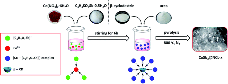 |
| | Scheme 1 Synthesis and growth mechanism for the catalysts of CoSb3 alloy nanoparticles wrapped with N-doped carbon layers. | |
Table 1 Experimental parameters of different catalysts
| Sample |
Co(NO3)2·6H2O |
C4H4KO7Sb·0.5H2O |
β-CD |
Urea |
| CoSb3@NCL-10 |
10 mg |
34 mg |
100 mg |
3.0 g |
| CoSb3@NCL-30 |
30 mg |
103 mg |
100 mg |
3.0 g |
| CoSb3@NCL-100 |
100 mg |
343 mg |
100 mg |
3.0 g |
| Co@NCL-30 |
30 mg |
0 mg |
100 mg |
3.0 g |
| NCL |
0 mg |
0 mg |
100 mg |
3.0 g |
2.2 Physical characterizations
The X-ray diffraction (XRD) patterns were obtained on a Rigaku/Max-3A with Cu Kα radiation. Scanning electron microscope (SEM) images were acquired on a Supra 55 Sapphire apparatus equipped with energy dispersive X-ray analysis system. Transmission Electron Microscope (TEM) and high-resolution transmission electron microscopy (HRTEM) images were recorded on a JEOL-2010 microscope with an accelerating voltage of 200 kV. X-ray photoelectron spectroscopy (XPS) spectra were collected on multifunctional imaging electron spectrometer (Thermo ESCALAB 250XI). The thermo gravimetric (TG) measurement was performed on a Thermo Gravimetric Analyzer (TA Instruments Q500) from room temperature to 800 °C with a heating rate of 10 °C min−1 under air.
2.3 Electrochemical measurements
Linear sweep voltammetry (LSV) was detected on CHI 660E electrochemical station (Shanghai, Chenhua) linked with a rotating disk electrode (RDE) in a typical three-electrode device which glassy carbon (GC) electrode (3 mm in diameter), Pt plate, and Ag/AgCl electrode were employed as the working electrode, counter electrode, and reference electrode, respectively. All of electrodes were immersed in oxygen-saturated 0.1 M KOH solution. The potentials in this work were converted to the reversible hydrogen electrode (RHE) by using the following equation:23| | |
ERHE = EAg/AgCl + 0.059pH + 0.197
| (1) |
The working electrode was fabricated as follows: 2.4 mg of prepared catalyst was dispersed in 1 mL of mixture solution (735 μL of water, 205 μL of isopropanol and 60 μL of Nafion (5 wt%, Sigma Aldrich)) by ultrasound (>60 min) to form a homogeneous slurry. Then the electro-catalyst ink (3 μL) was dropped onto the mirror-polished GC electrode and slowly dried at room temperature. The loading of catalyst was 100 μg cm−2. For comparison, the commercial Pt/C catalyst (20 wt%, Johnson Matthey) and IrO2 (Alfa) were also prepared with the same condition.
For ORR test, the LSV was operated from 1.0 V to 0.3 V (vs. RHE) with a scan rate of 10 mV s−1 at diverse rotation speed (400, 600, 900, 1200, 1600, 2000 and 2500 rpm). Koutecky–Levich (K–L) plots were evaluated at various potentials (0.30–0.45 V (vs. RHE)). The number of electrons transferred (n) was obtained according to the following K–L formula:
| | |
j−1 = jL−1 + jK−1 = (Bω1/2)−1 + jK−1
| (2) |
| | |
B = 0.2nFCoDo2/3ν−1/6
| (3) |
where
j,
jK,
jL, and
ω are the measured current density, kinetic-limiting current density, diffusion-limiting current density, and the angular velocity, respectively.
n,
F,
Co,
Do, and
ν represent the transferred electron number of the ORR, the Faraday constant, the bulk concentration of O
2, the diffusion coefficient of O
2, and the kinematic viscosity of the electrolyte, respectively.
k is the electron-transfer rate constant. For OER analysis, the LSV was measured from 1.0 V to 1.86 V (
vs. RHE) at 10 mV s
−1 with the fixed rotating speed of 1600 rpm and O
2-saturated condition.
2.4 Air electrode preparation and zinc–air battery tests
The slurry consists of Vulcan XC-72R and polyvinylidene fluoride (PVDF) with a mass ratio of 8![[thin space (1/6-em)]](https://www.rsc.org/images/entities/char_2009.gif) :
:![[thin space (1/6-em)]](https://www.rsc.org/images/entities/char_2009.gif) 1 was coated onto the carbon paper (Toray TGP-H-060) to form the air diffusion layer. The loading of slurry was about 2 mg cm−2. The catalyst ink was prepared by ultrasonic dispersion of 20 mg CoSb3@NCL-30 catalyst in the mixture of isopropanol (900 μL) and 5 wt% Nafion solution (100 μL). The 200 μL of the above catalyst ink was painted on the air diffusion layer and dried in vacuum at room temperature. The loading of the catalysts were about 1 mg cm−2. For comparison, the commercial Pt/C catalyst-based air electrode was also fabricated under the same manner.
1 was coated onto the carbon paper (Toray TGP-H-060) to form the air diffusion layer. The loading of slurry was about 2 mg cm−2. The catalyst ink was prepared by ultrasonic dispersion of 20 mg CoSb3@NCL-30 catalyst in the mixture of isopropanol (900 μL) and 5 wt% Nafion solution (100 μL). The 200 μL of the above catalyst ink was painted on the air diffusion layer and dried in vacuum at room temperature. The loading of the catalysts were about 1 mg cm−2. For comparison, the commercial Pt/C catalyst-based air electrode was also fabricated under the same manner.
The tests of rechargeable Zn–air battery were executed on a homemade device. The zinc plate, air electrode, and 6 M KOH with 0.2 M zinc acetate solution were served as the anode, the cathode, and electrolyte, respectively. Polarization and long-time galvanostatic charge–discharge tests were executed by CHI 660E electrochemical station with continuous oxygen supply from ambient air.
3. Results and discussion
3.1 Formation mechanism and structural characterization
The possible formation mechanism of the CoSb3@NCL samples could be described by Scheme 1. Firstly, Co2+ and [C4H4O7Sb]− derived from antimony potassium attracted each other by electrostatic field to form the Co–[C4H4O7Sb] complex in water solution. Then, β-CD (C source) and urea (N source) were added to the above solution. The β-CD molecules would successively coordinate with Co–[C4H4O7Sb] by the hydroxyls to further form [(β-CD)–Co–[C4H4O7Sb]] complex.24,25 Finally, after being thoroughly dried, the obtained precursor was pyrolyzed at 800 °C for 1 h in N2 atmosphere. During this step, the N-doped carbon layers (NCL) derived from β-CD and urea can simultaneously reduce Co–[C4H4O7Sb] complex to CoSb3 alloy, resulting in the formation of CoSb3@NCL nanocomposites.26 The possible reaction process can be described as follows:
| |
 | (5) |
| |
 | (6) |
| |
 | (7) |
The crystal phase structure of the different catalysts prepared at 800 °C for 1 h in N2 was firstly identified by XRD. As presented in Fig. 1, all diffraction peaks of CoSb3@NCL-30 can be readily indexed to the cubic phase of CoSb3 alloy (JCPDS no. 88-2437). No other characteristic peaks belong to Co, Sb, and their oxides are observed, indicating that the precursor has been completely reduced to CoSb3 alloy and then well protected by the carbon layers and inert N2 atmosphere. For comparison, the Co@NCL-30 and NCL samples were also characterized by XRD. The diffraction peaks of Co@NCL-30 can be indexed to the metallic cobalt (JCPDS no. 15-0806) and the broad diffraction peak at ∼26° appeared simultaneously in the XRD patterns of Co@NCL-30 and NCL samples could be ascribed to the (002) plane of carbon materials. The CoSb3 content of the CoSb3@NCL-30 composite was determined by thermogravimetric analysis (Fig. 2). According to TG result, the content of CoSb3 is calculated to be about 58.3 wt%. Need to be explained, the last weight increase in TG curve can be attributed to the high temperature oxidation of alloy nanoparticles under air condition.
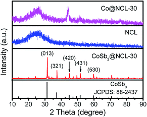 |
| | Fig. 1 XRD patterns of CoSb3@NCL-30, Co@NCL-30, and NCL. | |
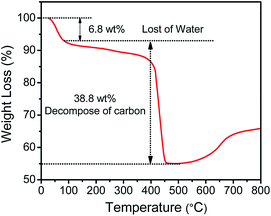 |
| | Fig. 2 TG curve of CoSb3@NCL-30 with a heating rate of 10 °C min−1 under air. | |
The XPS was carried out to identify the chemical composition and the bonding configuration of the CoSb3@NCL-30. In the survey spectra (Fig. 3a), the results reveal the existence of C (284.8 eV), N (398.8 eV), Sb (531.3 eV) and Co (780.7 eV) elements, which are in line with the results of XRD. In the high-resolution C 1s spectra (Fig. 3b), a set of peaks at 284.6, 285.4, 286.5, 289.3 and 292.7 eV belong to C![[double bond, length as m-dash]](https://www.rsc.org/images/entities/char_e001.gif) C, C–C, C–N, O
C, C–C, C–N, O![[double bond, length as m-dash]](https://www.rsc.org/images/entities/char_e001.gif) C–O, and π–π*, respectively, implying that the N element is successfully doped in carbon layers.27,28 Specifically, the π–π* peak (at 292.7 eV) demonstrates that the carbon layers is formed with graphitic-like structure.28 The high-resolution N 1s spectra (Fig. 3c) can be fitted to four N types: pyridinic N (398.2 eV), pyrrolic N (399.3 eV), graphic N (400.6 eV) and oxidized N (404.6 eV).29,30 It has been reported that the graphic N could greatly increase the limiting current density and the pyridinic N could improve the onset potential.30 In the high-resolution Co 2p spectra (Fig. 3d), the peaks with the binding energies of 780.4 and 778.6 eV are attributed to the Co 2p3/2 of Co(II) and Co(0), respectively. Moreover, the peaks at 782.6 and 785.2 eV should be the satellite peaks of Co 2p3/2 peaks.28
C–O, and π–π*, respectively, implying that the N element is successfully doped in carbon layers.27,28 Specifically, the π–π* peak (at 292.7 eV) demonstrates that the carbon layers is formed with graphitic-like structure.28 The high-resolution N 1s spectra (Fig. 3c) can be fitted to four N types: pyridinic N (398.2 eV), pyrrolic N (399.3 eV), graphic N (400.6 eV) and oxidized N (404.6 eV).29,30 It has been reported that the graphic N could greatly increase the limiting current density and the pyridinic N could improve the onset potential.30 In the high-resolution Co 2p spectra (Fig. 3d), the peaks with the binding energies of 780.4 and 778.6 eV are attributed to the Co 2p3/2 of Co(II) and Co(0), respectively. Moreover, the peaks at 782.6 and 785.2 eV should be the satellite peaks of Co 2p3/2 peaks.28
 |
| | Fig. 3 XPS spectrum of CoSb3@NCL-30. (a) Survey spectra and high-resolution spectra of (b) C 1s, (c) N 1s, (d) Co 2p. | |
Detailed morphological and structure data of the CoSb3@NCL-30 were characterized by SEM and TEM. SEM images (Fig. 4a) indicates that CoSb3 alloy nanoparticles with the diameter of 200–300 nm are well dispersed in the carbon matrix to form nanocomposites. The corresponding elemental mapping images also confirm the homogeneous distribution of Co, Sb, and N elements in carbon matrix (Fig. 4b). According to the EDS results, the N contents of CoSb3@NCL-10, CoSb3@NCL-30, and CoSb3@NCL-100 are 5.64%, 5.26% and 3.12%, respectively. The results demonstrate that although under the same experimental conditions of temperature, time and the same amount of β-CD and urea in the precursor, the N contents present a gradually downward trend with the increase of the amount of metal salts in the precursor. Because of the metal salts can be completely converted into alloy nanoparticles in the final product by the pyrolytic process, so it also means that the N content is decreased with the increase of the amount of CoSb3 nanoparticles in the composites, which is similar to some previous reports.31 The TEM image (Fig. 4c) show that the CoSb3 alloy nanoparticles are encapsulated in flexible carbon nanolayers and HRTEM image (Fig. 4d) unambiguously reveals the lattice fringe with d-spacing of 0.281 nm correspond to the (013) plane of CoSb3. The unique structure CoSb3 alloy nanoparticles wrapped with N-doped carbon nanolayers can not only enable faster transfer of electrons but also avoid agglomeration of alloy nanoparticles during the electrocatalytic reaction and charge–discharge process.32 For comparison, the morphology of other catalysts (including CoSb3@NCL-10, CoSb3@NCL-100, Co@NCL-30, and NCL) were also characterized and shown in Fig. 5. Among of them, NCL, which was prepared without any metal salts in the precursor, presents a graphene-like structure (Fig. 5a). When different amounts of Co(NO3)2·6H2O and C4H4KO7Sb·0.5H2O were introduced to the reaction system, the composite catalysts consist of CoSb3 (or Co) nanoparticles and carbon layers can be obtained. The quantity of the CoSb3 nanoparticles in the composite catalysts and the morphology of carbon are relevant to the amounts of Co(NO3)2·6H2O and C4H4KO7Sb·0.5H2O in the precursor. The CoSb3@NCL-10 shows a similar morphology to that of CoSb3@NCL-30 except for the different quantity of nanoparticles in the composites (Fig. 5b). However, the CoSb3@NCL-100 sample presents a quite different morphology compared to other CoSb3@NCL samples, in which the size of alloy nanoparticles became very large and the carbon morphology also changed from graphene-like nanolayers to irregular bulks (Fig. 5c).
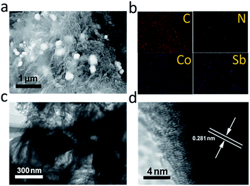 |
| | Fig. 4 (a) SEM image; (b) elemental mapping images; (c) TEM image; (d) HRTEM image of CoSb3@NCL-30. | |
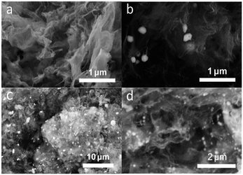 |
| | Fig. 5 SEM images of (a) NCL; (b) CoSb3@NCL-10; (c) CoSb3@NCL-100; (d) Co@NCL-30. | |
3.2 Electrochemical studies
The bifunctional catalytic capabilities of the oxygen electrocatalysts toward both ORR and OER are very important to rechargeable Zn–air batteries. LSV connected with a RDE was used to evaluate the electrocatalytic performance of different prepared catalysts and the benchmark Pt/C (20%) and IrO2 catalysts. Polarization curves for ORR in 0.1 M KOH electrolyte (O2-saturation) at the rotating speed of 1600 rpm are given in Fig. 6a. Among of all the prepared catalysts, the CoSb3@NCL-30 exhibits a remarkable ORR activity, only has a slightly lower half-wave potential (0.78 V) and small decrease of limiting diffusion current density (4.71 mA cm−2) compared to commercial Pt/C (0.79 V and 5.74 mA cm−2, respectively) at the same condition. In order to further study the ORR kinetics of CoSb3@NCL-30, RDE tests were carried out at various rotating speed from 400 rmp to 2500 rmp (Fig. 6b). The corresponding K–L plots are provided in Fig. 6c. The linearity and near parallelism of K–L plots indicate a first-order reaction kinetics to the concentration of O2 dissolved in the electrolyte. The number of electrons transferred (n) is calculated to be about 3.8 at the potentials range from 0.30 to 0.45 V (vs. RHE) by using the above K–L formula. This approximately 4-electron transfer pathway of CoSb3@NCL-30 is very critical for Zn–air battery application. Just like ORR determines the discharge performance, OER, which governs the charge performance, is also very important to rechargeable Zn–air battery. The OER catalytic activity of prepared CoSb3@NCL catalysts, Pt/C, and IrO2 were also studied and the corresponding LSV curves are given in Fig. 6d. Obviously, the CoSb3@NCL-30 also shows the best OER performance among all the prepared catalysts, which is just slightly worse than IrO2 and comparable to the catalysts reported by previous works.28,33–35 Thanks to the good ORR and OER catalytic activities, the obtained bifunctional CoSb3@NCL-30 catalyst and the commercial Pt/C as the contrast were further used as air cathodes to construct homemade two-electrode rechargeable Zn–air batteries, respectively (Fig. 7a). The corresponding discharge and charge polarization curves of CoSb3@NCL-30 and Pt/C are presented in Fig. 7b. From it, we can clearly find that the CoSb3@NCL-30 cathode shows a better discharge and charge curve compared to commercial Pt/C, with a smaller charge–discharge voltage gap and better round-trip efficiency. Furthermore, the maximum peak power density of CoSb3@NCL-30 (211 mW cm−2) is also higher than that of Pt/C (152 mW cm−2) (Fig. 7c). Long-term stability is also a key factor for the actual application of rechargeable Zn–air battery. The cycling durability of CoSb3@NCL-30 and the benchmark Pt/C were assessed by galvanostatic discharge–charge cycling tests (30 min discharge followed by 30 min charge in each cycle) operated at the current density of 10 mA cm−2 (Fig. 7d). It is clearly seen that the CoSb3@NCL-30 catalyst has a better cycling performance compared to Pt/C under the same condition. The initial discharge and charge potential of CoSb3@NCL-30 are 1.29 V and 2.02 V, respectively, indicating a voltage gap of 0.73 V and a round-trip efficiency of 64%. After 60 hours, only slight performance degradation was detected on CoSb3@NCL-30 cathode (the overall increment in the voltage gap was only 0.1 V). The excellent performance of Zn–air battery based on CoSb3@NCL-30 catalyst is comparable or even better than many reported relevant works (Table 2). Due to its high bifunctional ORR/OER electrocatalytic activity, excellent cycling stability, and low-cost, the CoSb3@NCL-30 catalyst has more practical application value in Zn–air battery than those noble metal-based catalysts.
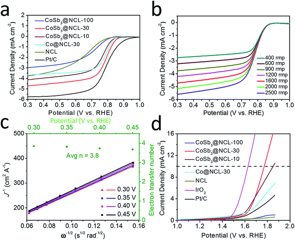 |
| | Fig. 6 Electrochemical characterizations of different catalysts. (a) ORR polarization curves of different catalysts at 1600 rpm. (b) ORR polarization curves of CoSb3@NCL-30 at different rotating rates. (c) The corresponding K–L plots of CoSb3@NCL-30 at different potentials (the green dots is the electron transfer number (n) per oxygen molecule (O2) at different potentials). (d) LSV curves of different catalysts for OER at 1600 rpm. | |
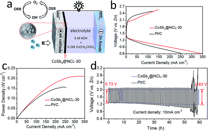 |
| | Fig. 7 Zn–air batteries performances. (a) Schematic representation of rechargeable Zn–air battery. (b) Discharge and charge polarization plots of the Zn–air batteries based on CoSb3@NCL-30 catalyst and Pt/C. (c) Corresponding power density plots of the Zn–air batteries based on CoSb3@NCL-30 catalyst and Pt/C. (d) Cycling performance of rechargeable Zn–air batteries based on CoSb3@NCL-30 catalyst and Pt/C at 10 mA cm−2 (30 min discharge followed by 30 min charge in each cycle). | |
Table 2 A comparison of the Zn–air battery performance of this work with recent relevant literatures
| Catalysts |
Loadinga (μg cm−2) |
Half-wave potential (V vs. RHE) |
Cycling current (mA cm−2) |
Cycle time (h) |
Fluctuation of discharge potential (EDP)/V (initial/end) |
Fluctuation of charge potential (ECP)/V (initial/end) |
Fluctuation of voltage gap V (ΔECP − ΔEDP) |
Source |
| The front loading data is used in RDE tests and the rear loading data is used is Zn–air batteries. LTFO-C is the abbreviation of LaTi0.65Fe0.35O3−δ nanoparticle-decorated nitrogen-doped carbon nanorods. |
| Ni/NiO/NiCo2O4/N-CNT-As |
240/300 |
0.74 |
5 (A g−1) |
70 |
1.20/1.14 |
1.95/1.94 |
0.05 |
Ref. 36 |
| LTFO-Cb |
—/1180 |
0.72 |
5 (A g−1) |
6 |
∼1.24/1.20 |
∼1.88/1.90 |
0.06 |
Ref. 37 |
| NCNT/CoO–NiO–NiCo |
210/530 |
0.83 |
20 |
17 |
∼1.11/1.06 |
∼2.03/1.97 |
Negligible change |
Ref. 38 |
| Fe@N–C |
249/2200 |
0.83 |
10 |
16.7 |
1.25/1.11 |
1.95/1.97 |
0.16 V |
Ref. 39 |
| Co–PDA–C |
500/1000 |
0.77 |
2 |
500 |
1.21/1.01 |
2.15/2.18 |
0.23 V |
Ref. 40 |
| CoMn2O4/N-rGO |
—/1180 |
— |
20 |
∼16.7 |
∼1.09/1.01 |
∼1.77/1.89 |
0.20 V |
Ref. 41 |
| CoS2(400)/N,S-GO |
536/1710 |
0.79 |
10 |
3.3 |
∼1.16/1.10 |
∼1.93/1.88 |
Negligible change |
Ref. 42 |
| FeCo@NC-750 |
800/1000 |
0.80 |
10 |
20 |
∼1.21/1.14 |
∼1.96/2.00 |
0.11 V |
Ref. 19 |
| NiCo2O4–CNTs |
100/2000 |
0.80 |
10 |
40 |
∼1.30/1.22 |
∼2.08/2.17 |
0.17 V |
Ref. 43 |
| CoSb3@NCL-30 |
100/1000 |
0.79 |
10 |
60 |
1.29/1.18 |
2.02/2.01 |
0.10 V |
This work |
4. Conclusion
In summary, a novel and efficient catalyst of CoSb3 alloy nanoparticles wrapped with N-doped carbon layers was successfully synthesized by a convenient one-step pyrolytic process of solid-phase precursor. The optimized CoSb3@NCL-30 catalyst exhibits excellent high bifunctional electrocatalytic activities both to ORR and OER in alkaline medium. The excellent electrocatalytic performance of CoSb3@NCL-30 can be attributed to the synergistic effect of the hybrid nanostructure. The outer N-doped carbon layers can not only facilitate electron transfer but also reduce the aggregation of CoSb3 nanoparticles to significantly increase the density of active sites. The outstanding electrochemical properties of CoSb3@NCL-30 were further proved in a rechargeable Zn–air battery by a discharge–charge cycling test operated at the current density of 10 mA cm−2 for 60 hours under ambient air. Considering the low-cost and simple synthetic method, our work provides a new strategy to large-scale synthesis of advanced bifunctional electro-catalysts to replace the noble metal-based catalysts for rechargeable Zn–air batteries.
Acknowledgements
The authors are grateful to the Fundamental Research Funds for the Central Universities (No. DUT17LK01).
References
- M. Winter and R. J. Brodd, Chem. Rev., 2004, 104, 4245–4269 CrossRef CAS PubMed.
- M. A. Rahman, X. Wang and C. Wen, J. Electrochem. Soc., 2013, 10, A1759–A1771 CrossRef.
- Y. Li and H. Dai, Chem. Soc. Rev., 2014, 43, 5257–5275 RSC.
- J. Fu, Z. P. Cano, M. G. Park, A. Yu, M. Fowler and Z. Chen, Adv. Mater., 2016, 29, 1604685 CrossRef PubMed.
- C. Zhu, H. Li, S. Fu, D. Du and Y. Lin, Chem. Soc. Rev., 2016, 45, 517–531 RSC.
- S. Zhang, Y. Shao, G. Yin and Y. Lin, J. Mater. Chem. A, 2013, 1, 4631 CAS.
- Y. Li, M. Gong, Y. Liang, J. Feng, J. E. Kim, H. Wang, G. Hong, B. Zhang and H. Dai, Nat. Commun., 2013, 4, 1805 CrossRef PubMed.
- T. Yu, D. Y. Kim, H. Zhang and Y. Xia, Angew. Chem., Int. Ed. Engl., 2011, 50, 2773–2777 CrossRef CAS PubMed.
- C. W. Xu, H. Wang, P. K. Shen and S. P. Jiang, Adv. Mater., 2007, 19, 4256–4259 CrossRef CAS.
- Y. Lee, J. Suntivich, K. J. May, E. E. Perry and Y. Shao-Horn, J. Phys. Chem. Lett., 2012, 3, 399–404 CrossRef CAS PubMed.
- R. Cao, J.-S. Lee, M. Liu and J. Cho, Adv. Energy Mater., 2012, 2, 816–829 CrossRef CAS.
- P. Ganesan, P. Ramakrishnan, M. Prabu and S. Shanmugam, Electrochim. Acta, 2015, 183, 63–69 CrossRef CAS.
- J. Deng, L. Yu, D. Deng, X. Chen, F. Yang and X. Bao, J. Mater. Chem. A, 2013, 1, 14868 CAS.
- L. Feng, Y. Liu and J. Zhao, Phys. Chem. Chem. Phys., 2015, 17, 30687–30694 RSC.
- J. Cho and J.-s. Lee, ACS Nano, 2015, 9, 6493–6501 CrossRef PubMed.
- M. Wu, Q. Tang, F. Dong, Y. Wang, D. Li, Q. Guo, Y. Liu and J. Qiao, Phys. Chem. Chem. Phys., 2016, 18, 18665–18669 RSC.
- J. K. Nørskov, J. Rossmeisl, A. Logadottir and L. Lindqvist, J. Phys. Chem. B, 2004, 108, 17886–17892 CrossRef.
- G. Zhang, W. Lu, F. Cao, Z. Xiao and X. Zheng, J. Power Sources, 2016, 302, 114–125 CrossRef CAS.
- P. Cai, S. Ci, E. Zhang, P. Shao, C. Cao and Z. Wen, Electrochim. Acta, 2016, 220, 354–362 CrossRef CAS.
- Y. Hou, H. Yuan, Z. Wen, S. Cui, X. Guo, Z. He and J. Chen, J. Power Sources, 2016, 307, 561–568 CrossRef CAS.
- Y. Chang, X. Mao, Y. Zhao, S. Feng, H. Chen and D. Finlow, J. Power Sources, 2009, 191, 176–183 CrossRef CAS.
- H. Li, Q. Wang, L. Shi, L. Chen and X. Huang, Chem. Mater., 2002, 14, 103–108 CrossRef CAS.
- M. Shen, C. Ruan, Y. Chen, C. Jiang, K. Ai and L. Lu, ACS Appl. Mater. Interfaces, 2015, 7, 1207–1218 CAS.
- G.-Y. Chen, B. Deng, G.-B. Cai, W.-F. Dong, W.-X. Zhang and A.-W. Xu, Cryst. Growth Des., 2008, 8, 2137–2143 CAS.
- G.-Y. Chen, Z.-Y. Wei, B. Jin, X.-B. Zhong, H. Wang, W.-X. Zhang, J.-C. Liang and Q. Jiang, Appl. Surf. Sci., 2013, 277, 268–271 CrossRef CAS.
- J. Yang, M. Wang, Y. Zhu, H. Zhao, R. Wang and J. Chen, J. Alloys Compd., 2011, 509, 7657–7661 CrossRef CAS.
- T. Jiang, Y. Wang, K. Wang, Y. Liang, D. Wu, P. Tsiakaras and S. Song, Appl. Catal., B, 2016, 189, 1–11 CrossRef CAS.
- J. Xi, Y. Xia, Y. Xu, J. Xiao and S. Wang, Chem. Commun., 2015, 51, 10479–10482 RSC.
- P. Xu, W. Chen, Q. Wang, T. Zhu, M. Wu, J. Qiao, Z. Chen and J. Zhang, RSC Adv., 2015, 5, 6195–6206 RSC.
- G. Fu, Z. Cui, Y. Chen, Y. Li, Y. Tang and J. B. Goodenough, Adv. Energy Mater., 2017, 7, 1601172 CrossRef.
- G. Zhang, W. Lu, F. Cao, Z. Xiao and X. Zheng, J. Power Sources, 2016, 302, 114–125 CrossRef CAS.
- B. Li, Y. Chen, X. Ge, J. Chai, X. Zhang, T. S. Hor, G. Du, Z. Liu, H. Zhang and Y. Zong, Nanoscale, 2016, 8, 5067–5075 RSC.
- Y. J. Sa, K. Kwon, J. Y. Cheon, F. Kleitz and S. H. Joo, J. Mater. Chem. A, 2013, 1, 9992 CAS.
- J. Sanetuntikul and S. Shanmugam, Nanoscale, 2015, 7, 7644–7650 RSC.
- J. Sanetuntikul, C. Chuaicham, Y.-W. Choi and S. Shanmugam, J. Mater. Chem. A, 2015, 3, 15473–15481 CAS.
- N. Ma, Y. Jia, X. Yang, X. She, L. Zhang, Z. Peng, X. Yao and D. Yang, J. Mater. Chem. A, 2016, 4, 6376–6384 CAS.
- M. Prabu, P. Ramakrishnan, P. Ganesan, A. Manthiram and S. Shanmugam, Nano Energy, 2015, 15, 92–103 CrossRef CAS.
- X. Liu, M. Park, M. G. Kim, S. Gupta, G. Wu and J. Cho, Angew. Chem., Int. Ed. Engl., 2015, 54, 9654–9658 CrossRef CAS PubMed.
- J. Wang, H. Wu, D. Gao, S. Miao, G. Wang and X. Bao, Nano Energy, 2015, 13, 387–396 CrossRef CAS.
- B. Li, Y. Chen, X. Ge, J. Chai, X. Zhang, T. S. Hor, G. Du, Z. Liu, H. Zhang and Y. Zong, Nanoscale, 2016, 8, 5067–5075 RSC.
- M. Prabu, P. Ramakrishnan and S. Shanmugam, Electrochem. Commun., 2014, 41, 59–63 CrossRef CAS.
- P. Ganesan, P. Ramakrishnan, M. Prabu and S. Shanmugam, Electrochim. Acta, 2015, 183, 63–69 CrossRef CAS.
- C. Ma, N. Xu, J. Qiao, S. Jian and J. Zhang, Int. J. Hydrogen Energy, 2016, 41, 9211–9218 CrossRef CAS.
Footnote |
| † Author contributions: Tian-bo Yang and Kai-Yuan Zhou contributed equally to this work. |
|
| This journal is © The Royal Society of Chemistry 2017 |
Click here to see how this site uses Cookies. View our privacy policy here.  Open Access Article
 b,
Guang-Yi Chen*b,
Wan-Xi Zhang*ab and
Ji-Cai Liangab
![[thin space (1/6-em)]](https://www.rsc.org/images/entities/char_2009.gif) :
:![[thin space (1/6-em)]](https://www.rsc.org/images/entities/char_2009.gif) 3) were also used to prepare composite catalysts. The resulting samples were accordingly named as CoSb3@NCL-10 and CoSb3@NCL-100, respectively. For the sake of comparison, the pristine N-doped carbon layers (NCL) and Co@NCL-30 catalyst obtained without C4H4KO7Sb·0.5H2O in the precursor were also prepared via the similar process described in Scheme 1. The detail experimental parameters of different samples were given in Table 1.
3) were also used to prepare composite catalysts. The resulting samples were accordingly named as CoSb3@NCL-10 and CoSb3@NCL-100, respectively. For the sake of comparison, the pristine N-doped carbon layers (NCL) and Co@NCL-30 catalyst obtained without C4H4KO7Sb·0.5H2O in the precursor were also prepared via the similar process described in Scheme 1. The detail experimental parameters of different samples were given in Table 1.

![[thin space (1/6-em)]](https://www.rsc.org/images/entities/char_2009.gif) :
:![[thin space (1/6-em)]](https://www.rsc.org/images/entities/char_2009.gif) 1 was coated onto the carbon paper (Toray TGP-H-060) to form the air diffusion layer. The loading of slurry was about 2 mg cm−2. The catalyst ink was prepared by ultrasonic dispersion of 20 mg CoSb3@NCL-30 catalyst in the mixture of isopropanol (900 μL) and 5 wt% Nafion solution (100 μL). The 200 μL of the above catalyst ink was painted on the air diffusion layer and dried in vacuum at room temperature. The loading of the catalysts were about 1 mg cm−2. For comparison, the commercial Pt/C catalyst-based air electrode was also fabricated under the same manner.
1 was coated onto the carbon paper (Toray TGP-H-060) to form the air diffusion layer. The loading of slurry was about 2 mg cm−2. The catalyst ink was prepared by ultrasonic dispersion of 20 mg CoSb3@NCL-30 catalyst in the mixture of isopropanol (900 μL) and 5 wt% Nafion solution (100 μL). The 200 μL of the above catalyst ink was painted on the air diffusion layer and dried in vacuum at room temperature. The loading of the catalysts were about 1 mg cm−2. For comparison, the commercial Pt/C catalyst-based air electrode was also fabricated under the same manner.


![[double bond, length as m-dash]](https://www.rsc.org/images/entities/char_e001.gif) C, C–C, C–N, O
C, C–C, C–N, O![[double bond, length as m-dash]](https://www.rsc.org/images/entities/char_e001.gif) C–O, and π–π*, respectively, implying that the N element is successfully doped in carbon layers.27,28 Specifically, the π–π* peak (at 292.7 eV) demonstrates that the carbon layers is formed with graphitic-like structure.28 The high-resolution N 1s spectra (Fig. 3c) can be fitted to four N types: pyridinic N (398.2 eV), pyrrolic N (399.3 eV), graphic N (400.6 eV) and oxidized N (404.6 eV).29,30 It has been reported that the graphic N could greatly increase the limiting current density and the pyridinic N could improve the onset potential.30 In the high-resolution Co 2p spectra (Fig. 3d), the peaks with the binding energies of 780.4 and 778.6 eV are attributed to the Co 2p3/2 of Co(II) and Co(0), respectively. Moreover, the peaks at 782.6 and 785.2 eV should be the satellite peaks of Co 2p3/2 peaks.28
C–O, and π–π*, respectively, implying that the N element is successfully doped in carbon layers.27,28 Specifically, the π–π* peak (at 292.7 eV) demonstrates that the carbon layers is formed with graphitic-like structure.28 The high-resolution N 1s spectra (Fig. 3c) can be fitted to four N types: pyridinic N (398.2 eV), pyrrolic N (399.3 eV), graphic N (400.6 eV) and oxidized N (404.6 eV).29,30 It has been reported that the graphic N could greatly increase the limiting current density and the pyridinic N could improve the onset potential.30 In the high-resolution Co 2p spectra (Fig. 3d), the peaks with the binding energies of 780.4 and 778.6 eV are attributed to the Co 2p3/2 of Co(II) and Co(0), respectively. Moreover, the peaks at 782.6 and 785.2 eV should be the satellite peaks of Co 2p3/2 peaks.28


