 Open Access Article
Synthesis, characterization and synergistic photocatalytic properties of yeast-assisted composite La0.7Sr0.3MnO3/TiO2
Pan Yuea,
Zhi-Xian Wei*a,
Xu-Hong Wu b,
He-Dan Zhanga and
Fan Yeb
aSchool of Environmental and Safety Engineering, North University of China, Taiyuan, Shanxi 030051, PR China. E-mail: zx_wei@126.com
bDepartment of Chemistry, Science Institute, North University of China, Taiyuan, Shanxi 030051, P. R. China
First published on 24th October 2017
Abstract
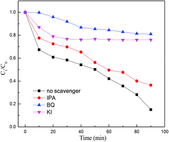
In order to identify a high-efficiency solar-light-driven magnetic photocatalyst, a series of powders such as perovskite La0.7Sr0.3MnO3, yeast-assisted La0.7Sr0.3MnO3 (Y-La0.7Sr0.3MnO3), Y-La0.7Sr0.3MnO3/TiO2 and TiO2 were prepared and characterized by photoluminescence spectroscopy (PL), UV-Vis diffuse reflectance spectroscopy (DRS), X-ray diffraction (XRD), transmission electron microscopy (TEM), X-ray photoelectron spectroscopy (XPS) and N2 adsorption–desorption (N2-BET). The magnetic and photocatalytic properties of the powders were also investigated. The experimental results show that, when the content of TiO2 in the composite Y-La0.7Sr0.3MnO3/TiO2 is 3.51 wt%, the Y-La0.7Sr0.3MnO3/TiO2 exhibits stronger absorption in the UV-Vis light region. A composite p–n heterojunction was formed and had the lowest photoluminescence (PL) intensity, indicating a higher separation efficiency of photogenerated charge carriers and an enhancement of the photocatalytic activity of the Y-La0.7Sr0.3MnO3/TiO2 composite. Under solar irradiation, Y-La0.7Sr0.3MnO3/TiO2 shows an obvious synergistic photocatalytic effect on orange (MO) wastewater, and the synergetic index is calculated to be 1.79. Furthermore, it still exhibits high photocatalytic activity after being reused 8 times. Moreover, Y-La0.7Sr0.3MnO3/TiO2 displays soft ferromagnetic behavior, has much higher magnetization and lower coercivity and remanence. Therefore, Y-La0.7Sr0.3MnO3/TiO2 can be recycled by an external magnetic field more easily and can be used repeatedly. Radical trapping experiments confirmed that the main reactive oxygen species (ROS) involved in the process of the photocatalytic reaction are the superoxide radical anion (˙O2−), hole (h+), and hydroxyl radical (˙OH), and the sequence of the contributions of the ROS to the photocatalytic activity of the composite is ˙O2− > h+ > ˙OH. Furthermore, the photocatalytic mechanism of Y-La0.7Sr0.3MnO3/TiO2 is proposed in this work.
Introduction
It is well known that multifunctional homogeneous photocatalysts with intrinsic magnetic properties can be recycled via a magnetic field. Therefore a lot of homogeneous catalysts with magnetization and photocatalytic properties have been prepared and the corresponding properties investigated recently, for example, rare-earth mixed chalcogenide Dy4S4Te3,1 multiporous ZnFe2O4 nanotubes,2 Ni2FeVO6 nanoparticles,3 (La0.5Bi0.2Ba0.2Mn0.1)FeO(3−δ),4 porous tetragonal-CuFe2O4 nanotubes,5 Ba-doped BiFeO3 nanoparticles,6 ferromagnetic ZrO2 nanostructures,7 CdS nanostructures,8 Bi5Fe0.95Co0.05Ti3O15 via europium doping,9 yttrium ferrite ceramic10 etc. Because of the excellent magnetism and photocatalytic activity of perovskite oxides under solar irradiation, it has become the focus of our research group and some perovskite oxides have been investigated and reported, such as LaFe0.5Mn0.5−xO3−δ, LaFe0.9Mn0.1−xO3−δ, La0.8Ba0.2Fe0.9Mn0.1O3−δ and La0.8Sr0.2Mn1−xTixO3−δ (x = 0–0.15).11–14It is reported that La1−xSrxMnO3 (x = 0–0.5) materials show superparamagnetic behaviors and the highest saturation magnetization could be obtained when x = 0.3.15 Furthermore, La1−xSrxMnO3 materials also show good electrical and catalytic properties, so they are always used as multifunctional materials. For example, they have been applied as cathode materials in solid oxide fuel cells,16–18 and used as catalysts in the degradation of NO19 and MO.14 Due to the narrow band gap, La1−xSrxMnO3−δ could exhibit good photocatalytic activity under solar light irradiation,20 and TiO2 displays excellent photocatalytic activities under UV irradiation. So, a composite La0.7Sr0.3MnO3/TiO2 could improve the utilization of solar energy. Besides, the construction of a heterojunction structure is also a means used in recent years to improve the catalytic activities of pure catalysts. This is because the heterojunction photocatalyst is favorable for the separation of photogenerated electron–hole pairs, so the photocatalytic properties are improved. Therefore, a composite La0.7Sr0.3MnO3/TiO2 was investigated in this study.
Generally speaking, perovskite oxides are usually synthesized at a relatively high calcination temperature, which makes perovskite oxides with very low specific surface areas. To overcome the obstacle of low specific surface areas of perovskite oxides, a lot of approaches have been studied. One of the most effective approaches is to synthesize porous nanostructures, prepared via a template method,21,22 emulsion method,23,24 spray reaction method,25 etc. Among the template methods, bio-templating has drawn more attention in the field of oxide material synthesis.26,27 Among many bio-templating agents, yeast can easily be obtained in a large amount in a short time without environmental pollution. Simultaneously, it has a short generation time and can be easily incubated. In addition, yeast as a template may significantly simplify the processing routes because both the synthesis of the template and modification of the template surface can be omitted.28 So yeast was chosen as a template to increase the specific surface area of La0.7Sr0.3MnO3 and improve its photocatalytic activity.
In a word, in order to identify a high-efficiency solar-light-driven magnetic photocatalyst, a series of powders such as perovskite La0.7Sr0.3MnO3, yeast-assisted La0.7Sr0.3MnO3 (Y-La0.7Sr0.3MnO3), Y-La0.7Sr0.3MnO3/TiO2 and TiO2 were prepared and characterized. Simultaneously, the magnetism, the synergistic photocatalytic properties and reusability were also investigated. In addition, we used a range of chemical probes and scavengers for reactive oxygen species (ROS) to interrogate the mechanism of photocatalytic degradation of MO.
Experimental
Materials
The starting chemicals for the target compounds were of analytical grade without further purification. La(CH3COO)3 (99.9%), Sr(CH3COO)2 (99%) and Mn(CH3COO)2·4H2O (99.9%) etc. were purchased from Aladdin Industrial Corporation. Butyl titanate was purchased from Fuchen Chemical Company (Tianjin, China). The powdered yeast was purchased from Angel Yeast Company. The solvents used in this work were purchased from Damao Chemical Company (Tianjin, China). MO was purchased from Tianjin Chemical Reagent Factory.Preparation of photocatalysts La0.7Sr0.3MnO3, Y-La0.7Sr0.3MnO3, Y-La0.7Sr0.3MnO3/TiO2 and TiO2
![[thin space (1/6-em)]](https://www.rsc.org/images/entities/char_2009.gif) :
:![[thin space (1/6-em)]](https://www.rsc.org/images/entities/char_2009.gif) Sr
Sr![[thin space (1/6-em)]](https://www.rsc.org/images/entities/char_2009.gif) :
:![[thin space (1/6-em)]](https://www.rsc.org/images/entities/char_2009.gif) Mn was 0.7
Mn was 0.7![[thin space (1/6-em)]](https://www.rsc.org/images/entities/char_2009.gif) :
:![[thin space (1/6-em)]](https://www.rsc.org/images/entities/char_2009.gif) 0.3
0.3![[thin space (1/6-em)]](https://www.rsc.org/images/entities/char_2009.gif) :
:![[thin space (1/6-em)]](https://www.rsc.org/images/entities/char_2009.gif) 1, and metal acetate salts were dissolved in deionized water; the mixed solution was named A. A was thermally decomposed in an oven under normal atmosphere at 800 °C for 1.5 h and left to cool down to room temperature before being ground to obtain La0.7Sr0.3MnO3.
1, and metal acetate salts were dissolved in deionized water; the mixed solution was named A. A was thermally decomposed in an oven under normal atmosphere at 800 °C for 1.5 h and left to cool down to room temperature before being ground to obtain La0.7Sr0.3MnO3.Characterization
X-ray diffraction (XRD) was used to identify the phase and crystalline nature of the samples, and was performed on a D/max-RB X-ray diffraction apparatus (Rigaku) with a Ni-filtered CuKα radiation source (λ = 1.5418 Å). UV-Vis DRS was conducted using a UV-Vis spectrophotometer (Hitachi, Japan), using BaSO4 as a reflectance sample, and the mass of all of the as-prepared samples was equal to 0.0020 g. The measurement of PL spectra was performed on a fluorescence spectrophotometer (F-2700, Hitachi) with a Xe lamp as the excitation source (a perovskite catalyst with a wavelength of 220 nm was used; under this wavelength the emission band of TiO2 was covered by a frequency-doubled peak, so the excitation wavelength of TiO2 was 265 nm). N2-physisorption analysis of the prepared catalysts was performed at 200 °C on a NOVA touch-LX4 surface area & pore size analyzer to obtain the textural properties of the catalysts (specific surface area and pore volume). The particle size and morphology of the samples were characterized by a JEM-2100 (200 kV) transmission electron microscope (TEM). The selected area electron diffraction (SAED) patterns from the TEM and high resolution TEM (HRTEM) images were analyzed. XPS analysis was performed by a PHI Quantera SXM apparatus, equipped with a standard Al Kα excitation source. The binding energy (BE) scale has been calibrated by measuring the C 1s peak (BE = 284.6 eV) from the ubiquitous surface layer of adventitious carbon. The magnetic measurements of the samples were carried out in a vibrating sample magnetometer (VSM) (VersaLad, Quantum Design Co., America) at room temperature in an applied magnetic field sweeping between ±30![[thin space (1/6-em)]](https://www.rsc.org/images/entities/char_2009.gif) 000 Oe. An image of the yeast cells was recorded with a polarizing microscope (TL-1530, Shanghai Di Lun Optical Instrument Co., Ltd.)
000 Oe. An image of the yeast cells was recorded with a polarizing microscope (TL-1530, Shanghai Di Lun Optical Instrument Co., Ltd.)
![[thin space (1/6-em)]](https://www.rsc.org/images/entities/char_2009.gif) 100 lux in the city of Taiyuan (112°33′00′′-E, 37°51′9′′-N). The photocatalytic activity of the as-prepared catalysts was evaluated using MO as a probe subject. In this experiment, 0.0050 g Y-La0.7Sr0.3MnO3, Y-La0.7Sr0.3MnO3/TiO2 and TiO2 were dispersed into 50.0 ml MO solution (10 mg l−1, pH = 3.0) in a glass reactor, which was put in the dark for 10 min to achieve adsorption–desorption equilibrium between MO and the photocatalyst. After that, the reactor was irradiated with sunlight under mechanical stirring. After the photocatalysis experiment, the powder was recovered from the solution with a magnet (50 mm × 50 mm × 10 mm, surface field of ∼3000 G), and the concentration of the MO solution was determined using the UV-Vis spectrophotometer according to its absorbance wavelength at 505 nm. 4.0 ml MO solutions were taken at regular 5 min intervals during the irradiation, and were analyzed using the UV-Vis spectrometer. The MO degradation percentage was calculated as:
100 lux in the city of Taiyuan (112°33′00′′-E, 37°51′9′′-N). The photocatalytic activity of the as-prepared catalysts was evaluated using MO as a probe subject. In this experiment, 0.0050 g Y-La0.7Sr0.3MnO3, Y-La0.7Sr0.3MnO3/TiO2 and TiO2 were dispersed into 50.0 ml MO solution (10 mg l−1, pH = 3.0) in a glass reactor, which was put in the dark for 10 min to achieve adsorption–desorption equilibrium between MO and the photocatalyst. After that, the reactor was irradiated with sunlight under mechanical stirring. After the photocatalysis experiment, the powder was recovered from the solution with a magnet (50 mm × 50 mm × 10 mm, surface field of ∼3000 G), and the concentration of the MO solution was determined using the UV-Vis spectrophotometer according to its absorbance wavelength at 505 nm. 4.0 ml MO solutions were taken at regular 5 min intervals during the irradiation, and were analyzed using the UV-Vis spectrometer. The MO degradation percentage was calculated as:| Degradation rate (%) = 100(C0 − Ct)/C0 | (1) |
Results and discussion
XRD analysis
The XRD patterns of the as-prepared La0.7Sr0.3MnO3, Y-La0.7Sr0.3MnO3 and Y-La0.7Sr0.3MnO3/TiO2 (3.51 wt%) are shown in Fig. 1. The samples exhibit a clear rhombohedral structure with characteristic 2θ values at 32.7°, 40.1°, 46.8°, 58.1° and 68.5° (JCPDS no. 89-0649). No other peak is found, indicating that the perovskite oxides La0.7Sr0.3MnO3, Y-La0.7Sr0.3MnO3 and Y-La0.7Sr0.3MnO3/TiO2 were formed. In addition, it is noted that all of the recorded diffraction spectra reveal only the diffraction peaks of perovskite oxide La0.7Sr0.3MnO3, without any additional diffraction peaks relating to Ti, which could be attributed to the low content of TiO2 (ref. 32) that did not result in any significant change in the crystalline phase of Y-La0.7Sr0.3MnO3/TiO2. As shown in Fig. 1, the diffraction peak positions of La0.7Sr0.3MnO3, Y-La0.7Sr0.3MnO3 and Y-La0.7Sr0.3MnO3/TiO2 do not change, but the intensities of the characteristic diffraction peaks of Y-La0.7Sr0.3MnO3 and Y-La0.7Sr0.3MnO3/TiO2 are weaker than those of La0.7Sr0.3MnO3. Additionally, the peaks of La0.7Sr0.3MnO3, Y-La0.7Sr0.3MnO3 and Y-La0.7Sr0.3MnO3/TiO2 (3.51 wt%) become wider and wider in sequence, indicating that the crystallite sizes decrease in sequence according to Debye–Scherrer’s formula, which is consistent with the results of the TEM. Those results indicate that the crystallite volumes indeed decrease with the addition of yeast, and that may result in bigger surface areas and higher photocatalytic activity of the as-prepared powders.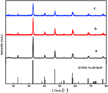 | ||
| Fig. 1 XRD patterns of (a) La0.7Sr0.3MnO3, (b) Y-La0.7Sr0.3MnO3, and (c) Y-La0.7Sr0.3MnO3/TiO2 (3.51 wt%). | ||
PL analysis
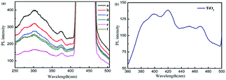
Photoluminescence (PL) is a powerful technique to investigate the separation efficiency of photogenerated electrons and holes of photocatalysts. PL emission results from the recombination of photogenerated electrons and holes and the PL intensity indicates the recombination rate of electron–hole pairs under light irradiation.33,34 In Fig. 2(a), the peaks at 405–500 nm are frequency-doubled peaks of the prepared powders (a–f). The PL spectra of Y-La0.7Sr0.3MnO3/TiO2, Y-La0.7Sr0.3MnO3 and La0.7Sr0.3MnO3 exhibit a wide and strong emission band which is observed between 250 and 405 nm. Here, it is worth noting that the PL spectrum of TiO2 is shown in Fig. 2(b) (where the excitation wavelength was 265 nm), and the emission band is between 360 and 500 nm. However, with an excitation wavelength of 220 nm, the emission band of TiO2 was covered by a frequency-doubled peak, so the PL intensity of TiO2 cannot be compared with the perovskite oxide Y-La0.7Sr0.3MnO3/TiO2. Therefore, the PL intensity of Y-La0.7Sr0.3MnO3/TiO2 was compared with that of Y-La0.7Sr0.3MnO3 to investigate the recombination rate of electron–hole pairs of the composites. As can be seen from Fig. 2(a), although the PL curve of Y-La0.7Sr0.3MnO3 is similar to that of La0.7Sr0.3MnO3, the PL intensity of Y-La0.7Sr0.3MnO3 is obviously weaker than that of La0.7Sr0.3MnO3, indicating that the recombination rate of electron–hole pairs is decreased and the catalytic activity of Y-La0.7Sr0.3MnO3 could be higher than that of La0.7Sr0.3MnO3. So Y-La0.7Sr0.3MnO3 was chosen to synthesize the composite Y-La0.7Sr0.3MnO3/TiO2 in this study. As shown in Fig. 2(a), the PL intensity decreases with increasing content of TiO2 from 0 to 3.51 wt%, and the PL intensity increases when the TiO2 content is up to 5.86 wt%. This result means that when the content of the TiO2 in Y-La0.7Sr0.3MnO3/TiO2 is 3.51 wt%, the composite Y-La0.7Sr0.3MnO3/TiO2 (3.51 wt%) has the lowest PL intensity, indicating that a Y-La0.7Sr0.3MnO3/TiO2 heterojunction can effectively suppress the recombination of electron–hole pairs and Y-La0.7Sr0.3MnO3/TiO2 (3.51 wt%) could be the best photocatalyst among the prepared powders.UV-Vis Diffuse Reflection Spectroscopy (DRS) analysis
The photoabsorption properties of the as-prepared TiO2, La0.7Sr0.3MnO3, Y-La0.7Sr0.3MnO3 and the composite Y-La0.7Sr0.3MnO3/TiO2 (3.51 wt%) (the four samples had the same mass in the UV-Vis DRS test) were detected by UV-Vis DRS, as shown in Fig. 3. It can be observed that only UV light is absorbed by the TiO2, which is ascribed to electron excitations of TiO2 from the valence band to the conduction band. While La0.7Sr0.3MnO3, Y-La0.7Sr0.3MnO3 and Y-La0.7Sr0.3MnO3/TiO2 (3.51 wt%) all exhibit broad absorption from UV to visible light, and the absorbance increases in sequence, which indicates that Y-La0.7Sr0.3MnO3/TiO2 (3.51 wt%), with higher absorbance, could have higher photocatalytic activities, and would be a high-efficiency solar-light-driven photocatalyst.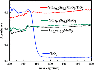 | ||
| Fig. 3 UV-Vis diffuse reflectance spectra of TiO2, La0.7Sr0.3MnO3, Y-La0.7Sr0.3MnO3, and Y-La0.7Sr0.3MnO3/TiO2 (3.51 wt%). | ||
XPS analysis
To verify if titanium exists in Y-La0.7Sr0.3MnO3/TiO2 (3.51 wt%), an XPS experiment was performed and the results are shown in Fig. 4. Fig. 4(a) shows that La, Sr, Mn, Ti, O and C are detected on the surface of the sample. Fig. 4(b) shows the XPS spectrum of the Ti 2p region. It demonstrates that two peaks for Ti 2p3/2 and Ti 2p1/2 are located at 457.8 eV and 463.6 eV, respectively.35 The spin orbit splitting energy between Ti 2p3/2 and Ti 2p1/2 is 5.8 eV and in agreement with the result of Ti 2p corresponding to Ti4+ and only consisting of the Ti4+ chemical state.36 Thus the existence of titanium in Y-La0.7Sr0.3MnO3/TiO2 (3.51 wt%) is verified, and is in the form of TiO2.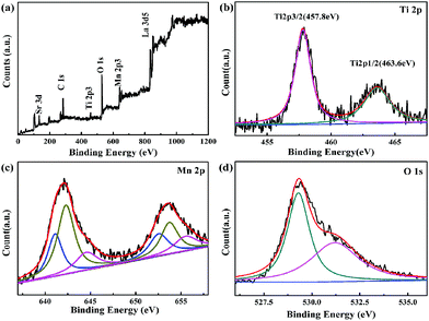 | ||
| Fig. 4 XPS spectra of Y-La0.7Sr0.3MnO3/TiO2 (3.51 wt%) sample, (a) survey scan, (b) Ti 2p, (c) Mn 2p, (d) O 1s. | ||
The XPS spectra of Mn 2p1/2 and Mn 2p3/2 of Y-La0.7Sr0.3MnO3/TiO2 (3.51 wt%) are shown in Fig. 4(c). The full width at half maximum (FWHM) of the Mn 2p3/2 peak for the sample is larger than 6 eV, which explicitly indicates the coexistence of Mn2+, Mn3+ and Mn4+ ions.37 It is reported that the binding energy (BE) values of Mn 2p3/2 and Mn 2p1/2 for the manganese cations in Mn2+, Mn3+ and Mn4+ are 641.0, 641.9, 642.1, 652.7, 653.1, and 653.8 eV, respectively.37–39 While in this study, the peaks of Mn 2p3/2 and Mn 2p1/2 for the manganese cations in Mn2+, Mn3+ and Mn4+ are 641.3, 642.3, 644.55, 652.55, 653.7, and 655.5 eV, respectively. It is obviously shown that the Mn 2p3/2 and Mn 2p1/2 shift to higher BEs, which have been found in previous literature.37 Meanwhile, the multivalent state of Mn can result in a higher catalytic oxidation activity. So Y-La0.7Sr0.3MnO3/TiO2 (3.51 wt%) could be used as a high efficiency photocatalyst.
In Fig. 4(d), O 1s is decomposed into two peaks at binding energies of 529.3 eV and 531.2 eV,40 where the two peaks stand for the lattice oxygen (Olatt) and surface-adsorbed oxygen (Oads), respectively. Oads is the important component for improving photocatalytic properties.
TEM analysis
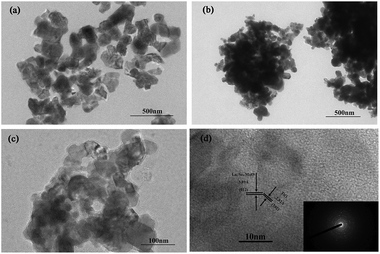
TEM images of La0.7Sr0.3MnO3, Y-La0.7Sr0.3MnO3 and Y-La0.7Sr0.3MnO3/TiO2 (3.51 wt%) are displayed in Fig. 5(a–c), and a high resolution TEM (HRTEM) image of Y-La0.7Sr0.3MnO3/TiO2 (3.51 wt%) with the corresponding SAED pattern is shown in Fig. 5(d). It is evident from the TEM images of the samples in Fig. 5(a–c) that the particle sizes of the catalysts are about 40–150 nm, with the average particle sizes of La0.7Sr0.3MnO3, Y-La0.7Sr0.3MnO3 and Y-La0.7Sr0.3MnO3/TiO2 (3.51 wt%) being about 132 nm, 63 nm and 43 nm (measured by nano measurer software), respectively. The results indicate that the addition of yeast reduces the particle volume of the samples (corresponding to the results of the XRD) and could enhance their photocatalytic activity. From Fig. 5(d), by measuring the lattice fringes, the resolved interplanar distances are determined to be around 2.82 and 3.89 Å, corresponding to the (102) plane of TiO2 (JCPDS no. 65-6429) and the (012) plane of Y-La0.7Sr0.3MnO3, respectively. As Y-La0.7Sr0.3MnO3 is a p-type semiconductor41 and TiO2 is an n-type semiconductor,42 the results above further demonstrate that composite Y-La0.7Sr0.3MnO3/TiO2 is successfully synthesized and a p–n heterojunction is formed. Here, the heterojunction interface formed in the Y-La0.7Sr0.3MnO3/TiO2 may help to effectively separate electron–hole pairs by shortening the charge transfer distance.43 This is in agreement with the PL results, indicating that the composite Y-La0.7Sr0.3MnO3/TiO2 could enhance the photocatalytic activity.BET analysis
The results of the adsorption–desorption isotherms indicate that TiO2, La0.7Sr0.3MnO3, Y-La0.7Sr0.3MnO3 and Y-La0.7Sr0.3MnO3/TiO2 (3.51 wt%) have type III isotherm shapes, which exhibit type H3 hysteresis loops as can be seen in Fig. 6(a).44 The adsorption and desorption lines overlaps completely in the low relative pressure range, which is mainly due to a presence of non-pores. Even though the samples in this study belong to the type III-class, there are hysteresis loops in the high relative pressure region (P/P0 > 0.8), which are proposed to be a result of bulk pores due to agglomeration of particles.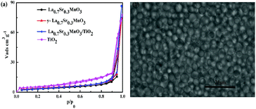 | ||
| Fig. 6 (a) Adsorption–desorption isotherms of N2 for TiO2, La0.7Sr0.3MnO3, Y-La0.7Sr0.3MnO3 and Y-La0.7Sr0.3MnO3/TiO2 (3.51 wt%). (b) Optical image of yeast cells. | ||
As shown in Table 1, the addition of yeast in the synthesis process of Y-La0.7Sr0.3MnO3 leads to an increase in the BET surface area. This can be attributed to the effect of the yeast template. An optical image of yeast cells shows that the shape of the yeast cells is spherical Fig. 6(b). During the preparation of Y-La0.7Sr0.3MnO3, hybrid precursors formed on the yeast cell walls were scattered evenly by the yeast template. When the hybrid precursors were calcined, the aggregation of the precursor was inhibited by the scattered spherical yeast cells. Hence, compared with La0.7Sr0.3MnO3 which was not added to yeast in the synthetic process, the BET surface area of Y-La0.7Sr0.3MnO3 increases.
| Sample | SBET (m2 g−1) | Pore radius Dv(r) (nm) |
|---|---|---|
| TiO2 | 1.85 | 8.67 |
| La0.7Sr0.3MnO3 | 11.86 | 16.64 |
| Y-La0.7Sr0.3MnO3 | 14.02 | 15.46 |
| Y-La0.7Sr0.3MnO3/TiO2 | 12.77 | 16.41 |
Magnetic properties
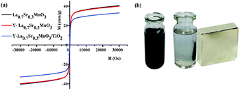
The room temperature magnetic hysteresis curves obtained from VSM measurements are shown in Fig. 7(a), and the magnetic parameters such as the saturation magnetization Ms, (Ms measured at 28.6 kOe), coercivity Hc and remanent magnetization Mr are given in Table 2. It is seen that the powders show no obvious magnetic hysteresis loops and low coercivities Hc and remanences Mr, and exhibit soft ferromagnetic behavior. The Ms value for Y-La0.7Sr0.3MnO3 is similar to the value for La0.7Sr0.3MnO3, but the corresponding value for Y-La0.7Sr0.3MnO3/TiO2 (3.51 wt%) is lower than those of both of them. The decrease in the value for Y-La0.7Sr0.3MnO3/TiO2 (3.51 wt%) is attributed to magnetization shielding provided by the non-magnetic TiO2. It is noted that in spite of the decrease in the Ms of Y-La0.7Sr0.3MnO3/TiO2 (3.51 wt%), the value is still large enough to achieve simple separation with an external magnetic field (50 mm × 50 mm × 10 mm, surface field of ∼3000 G) (Fig. 7(b)). As shown in the above experimental data, the composite Y-La0.7Sr0.3MnO3/TiO2 (3.51 wt%) exhibits stronger absorption in the UV-Vis light region, higher separation efficiency of photogenerated charge carriers and higher saturation magnetization, therefore, this study continuously investigates its photocatalytic activities under sunlight.| Sample | Hc (Oe) | Mr (emu g−1) | Ms (emu g−1) |
|---|---|---|---|
| La0.7Sr0.3MnO3 | 41.4 | 2.0 | 40.1 |
| Y-La0.7Sr0.3MnO3 | 38.3 | 1.9 | 39.4 |
| Y-La0.7Sr0.3MnO3/TiO2 | 24.8 | 0.7 | 32.6 |
Synergetic photocatalytic effect of Y-La0.7Sr0.3MnO3/TiO2 (3.51 wt%)
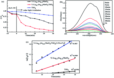
Before the photocatalysis, the adsorption performance of the photocatalysts was investigated. As shown in Fig. 8(a), in the dark the adsorption capacities of TiO2, Y-La0.7Sr0.3MnO3 and Y-La0.7Sr0.3MnO3/TiO2 (3.51 wt%) become stronger and stronger in sequence. Here, the adsorption capacities could be attributed to the specific surface areas and pore radii which could promote the adsorption capacity of the organic pollutants. In this study, the BET surface area and pore radius of TiO2 are smaller than those of Y-La0.7Sr0.3MnO3 and Y-La0.7Sr0.3MnO3/TiO2 (see Table 1), and hence it has the lowest adsorption capacity among the examined powders. The pore radius of Y-La0.7Sr0.3MnO3/TiO2 is bigger than that of Y-La0.7Sr0.3MnO3 while the specific surface area of the composite is smaller. The higher adsorption capacity of the composite shows that the pore radius is the deciding factor for the adsorption of large MO molecules.After adsorption, the photocatalytic activities of the as-prepared samples were evaluated by exposing them to the irradiation of solar light. For a blank experiment without catalysts, MO degradation under sunlight illumination is negligible (data not shown). As shown in Fig. 8(a), one can observe that Y-La0.7Sr0.3MnO3/TiO2 (3.51 wt%) possesses remarkably improved photocatalytic activity over Y-La0.7Sr0.3MnO3 and TiO2, and exhibits the best degradation efficiency with about 90% MO removal after 40 min of sunlight irradiation. In Fig. 8(b), it shows the change of absorbance with time. In addition, the degradation of MO approximately followed first order kinetics, as evidenced by the linear plot of −ln(C/C0) vs. photocatalytic time t (Fig. 8(c)). We obtained the rate constants of k1 (Y-La0.7Sr0.3MnO3/TiO2), k2 (Y-La0.7Sr0.3MnO3) and k3 (TiO2) to be 3.67 × 10⁻² min−1, 2.103 × 10⁻² min−1 and 0.546 × 10⁻² min−1, respectively. Furthermore, the MO degradation rate constant of Y-La0.7Sr0.3MnO3/TiO2 was found to be even higher than the sum of Y-La0.7Sr0.3MnO3 and TiO2, which suggests that the synergetic effect of Y-La0.7Sr0.3MnO3/TiO2 could contribute to the whole catalytic activity. Here, we quantitatively evaluate the synergetic effect in the MO degradation system by using the SI:45
| SI = k1/[(1 − x)k2 + xk3] | (2) |
The photocatalytic recyclability and repeated performance of Y-La0.7Sr0.3MnO3/TiO2 (3.51 wt%) were studied using the photocatalytic degradation of MO under sunlight irradiation for 50 min. After each cycling photocatalytic experiment, the photocatalyst was collected using a magnet for the next recycling. From Fig. 9, the photocatalytic degradation efficiency slightly dropped over 8 cycles, however, the photocatalyst Y-La0.7Sr0.3MnO3/TiO2 (3.51 wt%) still maintained high photocatalytic activity, indicating that Y-La0.7Sr0.3MnO3/TiO2 is very stable under the photocatalytic reaction conditions, and it can be recycled by magnetic field and possesses high reusability.
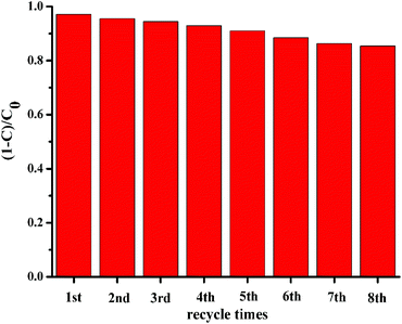 | ||
| Fig. 9 The recycled photocatalytic experiments of Y-La0.7Sr0.3MnO3/TiO2 (3.51 wt%) for the degradation of MO under sunlight. | ||
Photocatalytic mechanism
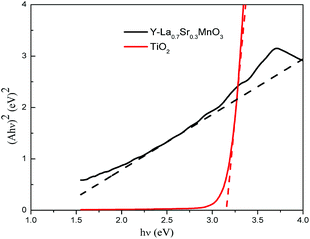
| (Ahν)n = hν − Eg | (3) |
The migration direction of the photogenerated charge carriers in the composite is related to the band edge positions of the semiconductors. The valence band (VB) and conduction band (CB) edge position of a semiconductor is estimated according to the following equation:31
| ECB = X − EC − 0.5Eg | (4) |
| EVB = ECB + Eg | (5) |
Based on the band gap structure calculations from the data of the UV-Vis diffuse reflectance spectra (Fig. 3), the calculated ECB and EVB edge positions of TiO2 are −0.29 and 2.91 eV, respectively. As for Y-La0.7Sr0.3MnO3, the ECB and EVB edge positions are 0.19 and 1.49 eV, respectively. The energy band structures of Y-La0.7Sr0.3MnO3 and TiO2 are schematically illustrated in Fig. 12, and it seems that the nested band structure is unfavorable for the separation of photogenerated carriers. However, it is known that Y-La0.7Sr0.3MnO3 is a p-type semiconductor, whose Fermi energy level (EF) is close to the valence band, and TiO2 is an n-type semiconductor, whose Fermi energy level is close to the conduction band. Moreover, Fermi energy levels of semiconductors can be substantially shifted and/or pinned by surface states in a composite.48 When the Y-La0.7Sr0.3MnO3 semiconductor is hybridized by TiO2 to form a p–n heterojunction structure, the electrons will diffuse in the opposite direction, resulting in an accumulation of negative charges in the Y-La0.7Sr0.3MnO3 region near the junction. Also, holes diffuse from the Y-La0.7Sr0.3MnO3 to the n-TiO2 region, forming a positive section in the vicinity of the heterojunction. When the Fermi levels of Y-La0.7Sr0.3MnO3 and TiO2 align under thermodynamic equilibrium conditions, an internal electric field directed from the n-TiO2 to the p-Y-La0.7Sr0.3MnO3 is simultaneously built to stop the charge diffusion. Meanwhile, the all energy band of Y-La0.7Sr0.3MnO3 was shifted upwards in this process whereas that of TiO2 was shifted downwards until an equilibrium state of Fermi levels of p-Y-La0.7Sr0.3MnO3 and n-TiO2 was obtained after hybridization. As a result, the CB bottom of Y-La0.7Sr0.3MnO3 became higher than that of the n-TiO2 semiconductor. Under solar irradiation, Y-La0.7Sr0.3MnO3 is excited and there is the generation of electron–hole pairs. According to the schema of Fig. 12, the photogenerated electrons move to the positive field (n-type TiO2) and then react with dissolved O2 in solution to produce reactive ˙O2−. At the same time, the photogenerated holes (h+) move into the negative field (p-type Y-La0.7Sr0.3MnO3) and oxidize OH− or H2O to ˙OH as well as directly oxidizing MO. Thus an efficient separation of photoinduced electron–hole pairs can be achieved in the formed heterojunction between the semiconductors, which leads to better photocatalytic activity than pure Y-La0.7Sr0.3MnO3 and pure TiO2. This is in agreement with the synergetic photocatalytic effect of Y-La0.7Sr0.3MnO3/TiO2 (3.51 wt%) described above.
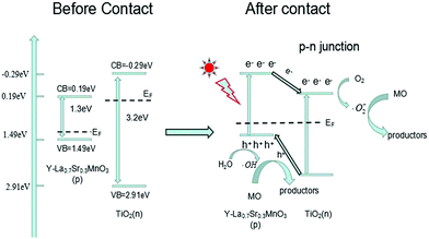 | ||
| Fig. 12 The proposed photocatalytic mechanism for the photodegradation of MO over Y-La0.7Sr0.3MnO3/TiO2. | ||
On the basis of the above results and previous studies, a possible enhancement mechanism for the photocatalytic activity of the Y-La0.7Sr0.3MnO3/TiO2 composite can also be proposed. Firstly, the hybridization of Y-La0.7Sr0.3MnO3 with TiO2 is beneficial to the improvement of the solar light absorbing capacity in this study, which has been demonstrated using UV-Vis DRS analysis. Secondly, the La0.7Sr0.3MnO3/TiO2 heterojunctions can enhance charge transfer and inhibit the recombination of photogenerated electron–hole pairs, which is very important for the improvement of photocatalytic activity. Hence, the Y-La0.7Sr0.3MnO3/TiO2 composite is a high-efficiency solar-light-driven magnetic photocatalyst.
Conclusions
In summary, the solar-light-driven Y-La0.7Sr0.3MnO3/TiO2 (3.51 wt%) with intrinsic magnetic properties can be synthesized and exhibits an obvious synergistic photocatalytic effect on the degradation of MO wastewater under sunlight. The enhanced photocatalytic performance could be mainly attributed to a decrease in the recombination of photogenerated carriers on the surface of the p–n heterojunction structure in Y-La0.7Sr0.3MnO3/TiO2. The photocatalytic activity of Y-La0.7Sr0.3MnO3/TiO2 (3.51 wt%) does not obviously decrease after 8 times recycling, indicating that the Y-La0.7Sr0.3MnO3/TiO2 can be recycled using an external magnetic field more easily and can be used repeatedly. It is believed that the composite Y-La0.7Sr0.3MnO3/TiO2 (3.51 wt%) photocatalyst would have potential applications in wastewater treatment in the future.Conflicts of interest
There are no conflicts to declare.Acknowledgements
This project was supported by the Natural Science Fund Council of China (No. 21371159) and the Science and Technology Item in Taiyuan Shanxi (No. 120247-13).Notes and references
- S. P. Guo and G. C. Guo, J. Mater. Chem. A, 2014, 2, 20621–20628 CAS.
- J. Yan, S. Gao and C. Wang, et al., Mater. Lett., 2016, 184, 43–46 CrossRef CAS.
- X. Qiao, Y. Huang and H. Cheng, et al., Appl. Surf. Sci., 2015, 359, 259–265 CrossRef CAS.
- I. Abdulkadir, S. B. Jonnalagadda and B. S. Martincigh, Mater. Chem. Phys., 2016, 178, 196–203 CrossRef CAS.
- P. Jing, J. Li and L. Pan, et al., J. Hazard. Mater., 2015, 284, 163–170 CrossRef CAS PubMed.
- T. Soltani and B. K. Lee, J. Hazard. Mater., 2016, 316, 122–133 CrossRef CAS PubMed.
- S. Kumar and A. K. Ojha, J. Alloys Compd., 2015, 644, 654–662 CrossRef CAS.
- B. Ahmed, S. Kumar and S. Kumar, et al., J. Alloys Compd., 2016, 679, 324–334 CrossRef CAS.
- Z. Zhu, X. Li and W. Gu, et al., J. Alloys Compd., 2016, 686, 306–311 CrossRef CAS.
- S. Jabbarzare, M. Abdellahi and H. Ghayour, et al., J. Alloys Compd., 2016, 688, 1125–1130 CrossRef CAS.
- Z. X. Wei, Y. Wang, J. P. Liu, C. M. Xiao and W. W. Zeng, Mater. Chem. Phys., 2012, 136, 755–761 CrossRef CAS.
- Z. X. Wei, Y. Wang, J. P. Liu, C. M. Xiao, W. W. Zeng and S. B. Ye, J. Mater. Sci., 2013, 1, 117–1126 Search PubMed.
- Z. X. Wei, C. M. Xiao, W. W. Zeng and J. P. Liu, J. Mol. Catal. A: Chem., 2013, 370, 35–43 CrossRef CAS.
- Z. X. Wei, S. B. Ye and X. M. Wang, Ceram. Int., 2016, 42, 9196–9203 CrossRef CAS.
- S. Daengsakul, C. Thomas and I. Thomas, et al., Nanoscale Res. Lett., 2009, 4, 839–845 CrossRef CAS PubMed.
- S. Kang, B. S. Kwak and B. H. Choi, et al., J. Ind. Eng. Chem., 2014, 20, 3960–3964 CrossRef CAS.
- T. Noh, J. Ryu and J. Kim, et al., J. Alloys Compd., 2013, 557, 196–201 CrossRef CAS.
- Y. B. Yang, W. Yin and S. T. Wu, et al., ACS Nano, 2015, 10, 1240–1248 CrossRef PubMed.
- J. Zhu, D. Xiao and J. Li, et al., Catal. Lett., 2009, 129, 240–246 CrossRef CAS.
- M. Ghiasi and A. Malekzadeh, Sep. Purif. Technol., 2014, 134, 12–19 CrossRef CAS.
- S. N. Tijare, S. Bakardjieva and J. Subrt, et al., J. Chem. Sci., 2014, 126, 517–525 CrossRef CAS.
- Y. C. Chang, C. Y. Lee and H. T. Chiu, ACS Appl. Mater. Interfaces, 2013, 6, 31–35 Search PubMed.
- R. Abazari, S. Sanati and L. A. Saghatforoush, Mater. Sci. Semicond. Process., 2014, 25, 301–306 CrossRef CAS.
- I. Shakir, M. Sarfraz and Z. Ali, et al., J. Alloys Compd., 2016, 660, 450–455 CrossRef CAS.
- Z. Han, V. W. C. Chang and L. Zhang, et al., Aerosol Air Qual. Res., 2012, 12, 1327–1335 CAS.
- Y. C. Chang, C. Y. Lee and H. T. Chiu, ACS Appl. Mater.Interfaces, 2013, 6, 31–35 Search PubMed.
- B. Lin, Q. Li and B. Liu, et al., Nanoscale, 2016, 8, 8178–8188 RSC.
- L. Yang, W. S. Guan and B. Bai, et al., J. Alloys Compd., 2010, 504, L10–L13 CrossRef CAS.
- D. F. Zhang, Russ. J. Phys. Chem. A, 2015, 89, 1948–1955 CrossRef CAS.
- R. Cruz-Ortiz and W. J. Jeremy, et al., J. Chem. Eng., 2017, 316, 179–185 CrossRef.
- H. J. Lu, L. l. Xu and B. Wei, et al., Appl. Surf. Sci., 2014, 303, 360–366 CrossRef CAS.
- X. Li, H. Wang and T. Chu, et al., Mater. Res. Bull., 2014, 57, 254–259 CrossRef CAS.
- K. S. Jeon, S. D. Oh and Y. D. Suh, et al., Phys. Chem. Chem. Phys., 2009, 11, 534–542 RSC.
- K. Rajkumar, P. Vairaselvi and P. Saravanan, et al., RSC Adv., 2015, 5, 20424–20431 RSC.
- R. E. Tanner, Y. Liang and E. I. Altman, Surf. Sci., 2002, 506, 251–271 CrossRef CAS.
- J. L. Ong, L. C. Lucas, G. N. Raikar and J. C. Gregory, Appl. Surf. Sci., 1993, 72, 7–13 CrossRef CAS.
- K. Kim, J. Jeong and A. K. Azad, et al., Appl. Surf. Sci., 2016, 365, 38–46 CrossRef CAS.
- H. Xu, Z. Qu and S. Zhao, et al., Chem. Eng. J., 2016, 292, 123–129 CrossRef CAS.
- W. Z. Si, Y. Wang and S. Zhao, et al., Environ. Sci. Technol., 2016, 50, 4572–4578 CrossRef CAS PubMed.
- F. M. Wang, G. L. Li, B. X. Shen, Y. Y. Wang and C. He, Chem. Eng. J., 2015, 263, 356–363 CrossRef CAS.
- M. Ghiasi and A. Malekzadeh, Sep. Purif. Technol., 2014, 134, 12–19 CrossRef CAS.
- M. J. Sun, J. Y. Hu and C. Y. Zhai, et al., Electrochim. Acta, 2017, 245, 863–871 CrossRef CAS.
- J. Li, Y. C. Yin and E. Z. Liu, et al., J. Hazard. Mater., 2017, 321, 183–192 CrossRef CAS PubMed.
- V. Gómez-Serrano, C. M. González-García and M. L. González-Martín, Powder Technol., 2001, 116, 103–108 CrossRef.
- L. Ai, C. Zhang and L. Li, et al., Appl. Catal., B, 2014, 148, 191–200 CrossRef.
- Y. F. Jia, C. J. Wu and B. W. Lee, et al., J. Hazard. Mater., 2017, 338, 447–457 CrossRef CAS PubMed.
- R. Ren and X. K. Qin, Rare Met. Mater. Eng., 2013, 42, 140–144 CAS.
- F. Z. Qiu, W. J. Li and F. Z. Wang, et al., Colloids Surf., A, 2017, 517, 25–32 CrossRef CAS.
| This journal is © The Royal Society of Chemistry 2017 |

