 Open Access Article
Creative Commons Attribution 3.0 Unported Licence
The electronic and diffusion properties of metal adatoms on graphene sheets: a first-principles study†
Yanan Tang *ab,
Hongwei Zhanga,
Zigang Shen*a,
Mingyu Zhaob,
Yi Lib and
Xianqi Dai*ab
aCollege of Physics and Electronic Engineering, Quantum Materials Research Center, Zhengzhou Normal University, Zhengzhou, Henan 450044, China. E-mail: yntang2010@163.com; shenzigang@zznu.edu.cn; xqdaizs@163.com; Fax: +86 371 65502273; Tel: +86 371 65502273
bCollege of Physics and Materials Science, Henan Normal University, Xinxiang, Henan 453007, China
First published on 30th June 2017
Abstract
We use first-principles calculations to investigate the geometric, electronic and magnetic properties of metal adatoms on two typical graphene substrates (monolayer and bilayer). Firstly, we study the adsorption behaviors and the doping effects of metal atoms on pristine and defective bilayer graphene sheets (PBG and DBG). It is found that the metal doping in DBG sheets is more stable than that in PBG sheets, since there are stronger covalent bonds between metal atoms and the dangling bonds of the carbon atoms. Compared to the unsupported graphene sheets, the Pt(111) supported graphene substrates have some effect on the stability of metal adatoms. Besides, the diffusion pathways of metal adatoms move from the upper pristine layer to the sublayer with large energy barriers, which is more difficult than that on the upper layer of DBG and the intercalated reaction from the upper layer to the sublayer, so the metal adatoms tend to penetrate into the graphene overlayer through the defective site. Moreover, the different metal adatoms can effectively regulate the electronic and magnetic properties of graphene sheets. This work provides valuable information on understanding the formation mechanisms of metal doping in graphene sheets, which would be vital for designing new functional metal–graphene composites.
1. Introduction
Graphene, a one-atom thick sheet of carbon atoms in a honeycomb arrangement, has attracted much interest due to its unique physical and chemical properties.1–3 In the preparation of graphene, it is inevitable that the introduced metal impurities and defects are always present in the crystals,4 which has a significant effect on the physical properties of graphene, such as the carrier transport and thermal conductivity.5,6 In addition, the structural defects or dopants into graphene can effectively tune the electronic structure and magnetic property of graphene sheets.7–9 Recently, some experimental work created vacancies using high energy atoms and filled these vacancies with desired dopants.10–12 Ambrosi et al. demonstrated metallic impurities present within the graphite sheets and that these impurities can regulate the electrocatalytic property of graphene.13Compared with the monolayer graphene, the bilayer graphene exhibits unique electronic properties.14,15 Some studies confirmed that the energy gap and magnetic property of multilayer graphene could be manipulated by applying an external electronic field and adding the metal substrates or metal adatoms.16–21 Recently, Liu et al. discussed the experimental and computational studies related to deposition of metals on various substrates supported graphene sheets.22 In the growth processes of bilayer graphene on metal substrates,23–26 the metal atoms within substrates are directly deposited into graphene.27 Sometimes it is difficult to evaluate the effects of specific factors with experiment, such as the strength of bonding between metal and carbon atoms, as well as the stable adsorption sites and diffusivity of metal atoms on graphene sheets. In comparison, the theoretical computations evaluation has become increasing important, which can tell us how metal adatoms could diffusion or interaction with graphene sheets. Herein, direct observation of the incorporation and migration of metal atoms on graphene sheets will give important information for the formation mechanism of metal–graphene composites.
Some examples about the interaction between the metal adatoms and monolayer graphene were recorded28–31 and then examined the stability of metal adatoms on pristine graphene sheet. However, only a few studies have been reported about the possible adsorption positions of metal adatoms at graphene interlayer. Recently, the doping of a graphene film when grown on Pt substrates or others metallic substrates have been investigated,32–34 yet it is still not well understand how to describe the adsorption behaviors of metal adatoms on metal supported graphene substrates.
The experimental results performed that metallic impurities (Cu, Fe and Ni) present within the graphene layers,10,13 yet the specific structure of metal-deposited multilayer graphene has not been investigated. Previous studies shown that the metal atoms on defective graphene sheet have difference trapping zones and diffusion barriers35 and the adsorption property of metal atom on graphene sheets are observed,36 however, there is a lack of systematical analysis about the trend of metal atoms diffusion on bilayer graphene. Because the metallic Fe, Ni and Cu atoms often are used as substrates or catalysts,37–39 it is necessary to explore the adsorption property and diffusion pathways of metal adatom on graphene sheets (monolayer and bilayer). Therefore, the geometric stability of metal adatom on graphene films with (or without) supported metal substrates are comparably analyzed, which would be useful for understanding different behavior of metal nucleation and grown on graphene layers.
In this work, the stable geometries, electronic structures and diffusion behaviors of metal adatoms on different graphene sheets are investigated using the density functional theory (DFT) calculations. Compared with the pristine bilayer graphene (PBG), it is found that the metal adatoms have larger adsorption energies and less diffusion barriers on defective bilayer graphene (DBG) with a single vacancy (SV). In addition, the metal mobility and intercalation reaction with increasing graphene thicknesses and on the Pt(111) substrate supported graphene sheets are comparably investigated, including the relationship between the adsorption energies and diffusion barriers, existing within the metal adatoms and graphene substrates. The study allows us to understand the formation mechanism of metal impurities in graphene sheet, which would provide a reference for designing new functional graphene-based materials.
2. Theoretical methods
The spin-polarized DFT calculations are performed using the Vienna ab initio simulation package (VASP).40,41 To improve the calculation efficiency, core electrons are replaced by the projector augmented wave (PAW) pseudo-potentials42 and the generalized gradient approximation of Perdew, Burke and Ernzernhof (PBE)43 to describe the exchange and correlation. The C 2s2p, Fe, Co, Ni, Cu 3d4s states are treated as valence electrons. The Kohn–Sham orbitals are expanded using plane waves expansion with an energy cutoff of 450 eV and the convergence criterion for the electronic self-consistent iteration is set to 10−5 eV. The energy of an isolated atom is simulated using a cubic cell of 15 × 15 × 15 Å3. The monolayer (or bilayer) graphene substrates is represented using a hexagonal supercell containing 32 (or 64) carbon atoms and a vacuum layer of 20 Å along the z direction placed between the sheets. The Brillouin zone (BZ) integration is sampled using a 5 × 5 × 1 Γ-centered Monkhorst–Pack (MP) grid and a Γ-centered MP grid of 15 × 15 × 1 is used for the final density of states (DOS) calculations.The calculated lattice constant of graphene is 2.47 Å, which is slightly larger than the experimental value of 2.46 Å.44 The optimized C–C bond value is 1.43 Å. Bader charge analysis45 is used to evaluate the atomic charges and electrons transfer in the adsorption process. The climbing image nudged elastic band method (CI-NEB)46–48 is employed to investigate the saddle points and minimum energy paths (MEPs) for the diffusion of metal adatoms on graphene substrates. The optimized structures corresponding to reactants and products of the elementary reactions are tested by means of frequency calculations. According to the frequency calculations, the structures with no imaginary frequency correspond to the most stable configurations, which can be chosen as the initial state (IS) and final state (FS) in the chemical reactions, while those with one imaginary frequency correspond to the metastable states, which can be viewed as the transition states (TS). A number of intermediate images are constructed along the diffusion pathways between the IS and FS, and the spring force between adjacent images is set to be 5.0 eV Å−1. Images are optimized until the forces on each atom are less than 0.02 eV Å−1.
3. Results and discussion
3.1 Adsorption energies and stable geometries
In order to estimate the preference site of metal adatom anchors on graphene sheets, the adsorption energy (Eads) is calculated using the following expression:| Eads = EA + EB − EAB |
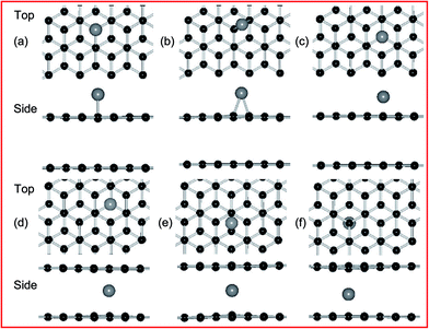
According to the previous results,21,49 the adsorption of metal atom is placed at three sites of high symmetry, belonging to the top and bottom layer of PBG substrates, namely, the top (T) site directly above a carbon atom, the bridge (B) site at the midpoint of a carbon–carbon bond, and the hollow (H) site at the center of a hexagonal. For example, the top and side views of optimized configurations of metal adatoms (such as Ni atom) on PBG sheets (PBG–M) are shown in Fig. 1. Table 1 listed the calculated adsorption energies for Fe, Co, Ni and Cu anchor at three symmetric positions. The preferred site is the one which has the largest adsorption energy. The bond length (dm–c) defined as the distance between metal adatom and neighboring carbon atoms within graphene sheets. For the top layer of PBG, it is found that the Fe, Co and Ni atom prefer to sit at the H site, the adsorbed Ni atom has a larger adsorption energy (1.70 eV) than that of the Fe (0.94 eV) and Co (1.40 eV), and the corresponding transferred electrons from metal adatom to graphene is 0.55 e (Ni), 0.84 e (Fe) and 0.71 e (Co), respectively. In comparison, the Cu atom prefers to be adsorbed at the T site with the small Eads of 0.29 eV. Based on the interconfigurational energies of Fe, Co and Ni atoms,50 the Fe atom requires the greatest energy per unit charge transferred from an s orbital to a d orbital while Ni requires the least energy, so the losing more electrons of Fe adatom bonds weakest to graphene while the strongest bonding of Ni provides less transferred electrons. The bond length (dm–c) of the metal adatoms on the top layer of graphene is 2.11 Å (Fe), 2.11 Å (Co), 2.12 Å (Ni) and 2.06 Å (Cu), respectively, which is similar to the metal adatoms on pristine monolayer graphene (PMG).51
| Adatom | Sites | Substrates | |||||
|---|---|---|---|---|---|---|---|
| PBG (top) | PBG (bottom) | PMG | |||||
| Eads (eV) | dm–c (Å) | Eads (eV) | dm–c (Å) | Eads (eV) | dm–c (Å) | ||
| Fe | T | 0.44 | 2.15 | 2.16 | 2.04 | 0.52 | 2.08 |
| B | 0.42 | 2.27 | Unstable | 0.49 | 2.20 | ||
| H | 0.94 | 2.11 | 2.15 | 2.22 | 1.03 | 2.09 | |
| SV | 7.36 | 1.76 | 7.98 | 1.78 | 7.74 | 1.76 | |
| Co | T | 0.81 | 1.88 | 2.30 | 1.98 | 0.76 | 1.87 |
| B | 0.84 | 1.96 | 2.38 | 2.07 | 0.82 | 1.96 | |
| H | 1.40 | 2.11 | 2.57 | 2.20 | 1.32 | 2.11 | |
| SV | 7.83 | 1.76 | 8.29 | 1.80 | 8.51 | 1.77 | |
| Ni | T | 1.41 | 1.86 | 2.83 | 2.01 | 1.34 | 1.86 |
| B | 1.46 | 1.94 | 2.86 | 2.05 | 1.42 | 1.94 | |
| H | 1.70 | 2.12 | 2.83 | 2.23 | 1.64 | 2.12 | |
| SV | 6.90 | 1.79 | 7.21 | 1.84 | 6.98 | 1.80 | |
| Cu | T | 0.29 | 2.06 | 1.09 | 2.02 | 0.20 | 2.07 |
| B | 0.25 | 2.17 | 1.26 | 2.09 | 0.21 | 2.16 | |
| H | 0.13 | 2.39 | 1.10 | 2.34 | 0.06 | 2.36 | |
| SV | 3.58 | 1.87 | 3.89 | 1.93 | 3.64 | 1.87 | |
Herein, we move on to the study of metal adatoms on the bottom layer of graphene, it is a worthwhile exercise to investigate about the adsorption behaviors of metal adatoms within the PBG sheets. Compared to the top layer of PBG, the stable adsorption sites of metal adatoms on the bottom layer have been changed to some extent, as shown in Table 1. The Fe adatom can be stabilized either at the T site (2.16 eV) or the H site (2.15 eV) with almost the approximate adsorption energy, while it is unstable at the B site. For the Co adatom, the H site (2.57 eV) is still more stable than the other sites (T and B), which is also larger than that on the top layer (H site, 1.40 eV). In addition, the adsorbed Ni adatom at the B site has the slightly larger Eads (2.86 eV) than that on the T and H site (2.83 eV), the smaller energy difference between adsorptions site indicates that the possible diffusion for intercalated Ni adatom takes place within PBG sheets. For the Cu adatom, the adsorption site at the B site is more stable than the other sites, which has a relatively large Eads value. In all, the metal adatoms have larger adsorption energies on the bottom layer of PBG than those on the top layer, since the intercalated metal adatoms interact with the more number of neighboring carbon atoms (including the upper and below layers) and thus exhibit the high stability.
On the other hands, the formed metal doping at the DBG (DBG–M) is modeled by substituting a carbon atom with one metal atom, the top and side views of fully relaxed structures are shown in Fig. 2 for the two doping configurations (upper and below SV site). Fig. 2(a) and (b) are for the T site doping (directly on top of a carbon atom), and the corresponding calculated results are shown in Table 1. For the adsorption energies of two configurations, the doped metal atoms are moved out of the graphene surface to get more space due to its larger atomic radius than that of the carbon atom, and the corresponding bond lengths between the doped metal adatoms and neighboring carbon atoms (below SV site) is 1.78–1.93 Å. Generally, a higher value of adsorption energy indicates a stronger preference for the structure. For the DBG substrate, the adsorption energies of metal adatoms at the below SV site (3.89–8.29 eV) are larger than those at the upper SV site (3.58–7.83 eV), indicating that these adatoms more likely penetrate into graphene overlayer through the SV site. In the next section, we will discuss the migration of metal atoms through a predefined pathway of defect created in graphene sheets. Compared with the PBG sheets, the metal dopants in the DBG sheet would be stable enough due to the formation of strong covalent bonds between the metal atoms and the under-coordinated C atoms of SV site, which is in accordance with the results.35,38
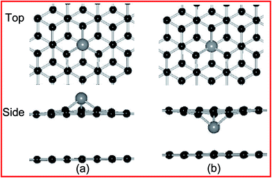 | ||
| Fig. 2 Top and side views of the geometric structures for Ni doping at DBG, including (a and b) upper and below SV site. Black and gray balls represent C and Ni atoms, respectively. | ||
Some results shown that metal substrates could influence the surface reactivity of the bilayer graphene films.33,34 For graphene supported on Pt substrates, we directly observe the adsorption stability of metal atoms, which provides an important reference to understand the interaction between metal adatoms and graphene sheets. As an important reference, the metallic Pt(111) substrate-supported graphene films is performed in slab geometry: a four-layer slab consists of 48 Pt atoms with a graphene (monolayer or bilayer) places on one side of the slab. For example, the most stable configuration of Ni adatom anchors on top (or bottom) layer of PBG and DBG substrates are shown in Fig. S1,† and the corresponding adsorption energies and bond distances are listed in Table 2. For the Pt(111) supported graphene substrate, the stable adsorption sites and energies of metal adatoms are changed to some extent, for example, the adsorption energies of Ni atom (at the H site) are changed from 1.77 to 3.05 eV for the PMG and PBG sheet, and from 6.85 to 7.19 eV for the Ni dopant in DMG and DBG, respectively. Moreover, the anchored adatom at SV site is still the most stable configuration as compared to the other sites (H, B and T). Compared with the unsupported graphene sheets, it is found that the increased energies and less stable adsorption sites of metal adatoms anchor on Pt(111) supported graphene substrates, as shown in Table 2. This means that the presence of Pt(111) substrate is a better candidate for improving the dispersion of metal adatoms and maintaining the high stability of supported catalysts on graphene sheets. This result provides a beneficial reference for the metal modified or doping of graphene films supported on metal substrates.
| Pt substrate | PBG (top) | PBG (bottom) | PMG | ||||
|---|---|---|---|---|---|---|---|
| Adsorption sites | Eads (eV) | dm–c (Å) | Eads (eV) | dm–c (Å) | Eads (eV) | dm–c (Å) | |
| Fe | T | 0.85 | 2.21 | 2.42 | 2.04 | 0.96 | 2.07 |
| B | 0.60 | 2.25 | Unstable | 0.85 | 2.33 | ||
| H | 1.32 | 2.13 | 2.34 | 2.01–2.21 | 0.51 | 2.08–2.10 | |
| SV | 6.99 | 1.76 | 7.73 | 1.78 | 6.83 | 1.76 | |
| Co | T | Unstable | 3.16 | 2.04 | 1.52 | 1.92 | |
| B | Unstable | Unstable | Unstable | ||||
| H | 2.05 | 2.11 | 3.02 | 2.19 | 2.21 | 2.13 | |
| SV | 7.95 | 1.76 | 8.43 | 1.78 | 7.82 | 1.76 | |
| Ni | T | 1.12 | 1.86 | 3.03 | 2.01 | 1.41 | 1.87 |
| B | 1.26 | 1.95 | Unstable | 1.36 | 1.97 | ||
| H | 1.77 | 2.12 | 3.05 | 2.14–2.35 | 1.88 | 2.13 | |
| SV | 6.95 | 1.79 | 7.19 | 1.83 | 6.85 | 1.79 | |
| Cu | T | 0.47 | 2.08 | Unstable | 0.68 | 2.05 | |
| B | 0.42 | 2.18 | Unstable | 0.69 | 2.12–2.14 | ||
| H | 0.36 | 2.02 | 1.55 | 2.18–2.54 | 0.59 | 2.30–2.34 | |
| SV | 3.61 | 1.88–1.90 | 3.93 | 1.93–1.97 | 3.54 | 1.87–1.90 | |
For the PBG sheets, although the Fe, Co and Ni adatoms on the bottom layer have larger adsorption energies than that on the top layer, yet the small energy difference indicates that the metal adatoms may easily move and aggregate to form metal cluster. For the DBG substrate, the metal adatoms have larger adsorption energies than that on the PBG sheets, especially, the Fe, Co and Ni adatoms below the SV site are quite stable (>7.0 eV) as compared with the Cu atom, which can facilitate the well-dispersed atoms and avoid the formation of metal cluster. Although the supported Pt(111) substrate has more or less effects on the adsorption energy of metal adatoms on graphene sheets, but it dose not affect the most preferable configuration for metal dopants in DMG and DBG sheets.
3.2 Electronic structure and magnetic property
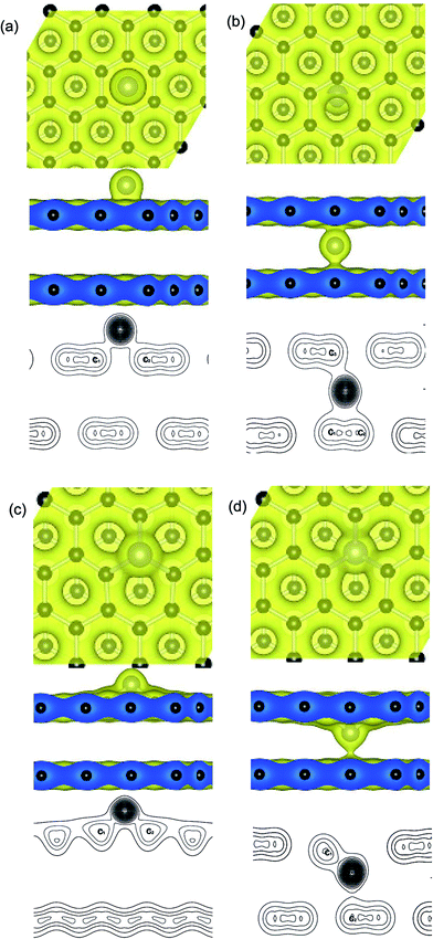
Distributions of charge density on planes that pass through the metal adatoms and neighboring carbon atoms at the upper and below graphene layers, such as the Ni atom anchors on the PBG sheets is shown in Fig. 3. It is found that two typical adsorption sites exhibit similar charge density distributions, including the H site of upper layer and the B site of bottom layer. As shown in Fig. 3(a), the H site for Ni adatom is the most stable configuration as compared with the other sites (T and B) and the bond length between Ni and C atoms is 2.12 Å. The transferred electron (0.55 e) occurs between the π states of graphene and the 3d states of Ni atom. One can see that there is a significant covalent-bonding character between the Ni adatom and the carbon atoms on the hexagonal ring of the upper graphene layer (see the valence charge density plots). In addition, the stable configuration for interaction between the Ni atom and neighboring carbon atoms at the B site are shown in Fig. 3(b). The bond length from Ni to neighboring two C atoms of the bottom layer is 2.04 and 2.06 Å, and the bond length to the carbon atom on the upper layer is 2.01 Å. The bonding electrons distribution between the intercalated Ni atom and PBG sheets also exhibits the covalent-bonding feature. Noting that the more electrons (0.59 e) concentration appears between the Ni atom and carbon atoms (upper and bottom layer), so the intercalated Ni adatom within PBG is more stable than that on the upper layer.For the Ni-doped graphene layer, the electronic states retain its localized character around the Ni atom, as shown in Fig. 3. Compared with the Ni adatom on PBG substrate, there are more transferred electrons (0.72 e and 0.82 e) move from Ni dopant to DBG substrates, as shown in Fig. 3(c) and (d). It is found that the large value of charge density exist in the doped Ni atom and the dangling bond of carbon atoms, indicating that the more pronounced charge densities between Ni and DBG interface exhibits a covalent-bonding character. Hence, the strength of Ni doping is largely determined by the charge redistribution that takes place at their interfaces. As shown in Fig. 3(b)–(d), the valence charge density plots show that the transferred electrons from the Ni adatom to the carbon atoms in the bottom layer and the increased charge densities at the bottom layer enhance the Ni–PBG (or DBG) interaction. So, the intercalated Ni atom within PBG (or DBG) sheets is much more stable than that on the upper layer of graphene sheets. The intercalated atom breaks the sp2 hybridization of carbon atoms within graphene and regulates the redistribution of charge density between adsorbate and substrate, resulting in the change of covalent bonds strength.52
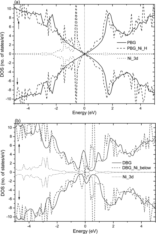
Fig. 4 shows the total DOS (TDOS) and partial DOS (PDOS) of the Ni adatom anchors on the PBG and DBG substrates, which are defined as PBG–Ni and DBG–Ni, respectively. It is well known that the PMG system exhibits nonmagnetic characters due to its symmetric spin channels.35,53 Compared with the PMG, the zero-gap is opened (about 0.4 eV) in the DOS plots of PBG system, as well as the asymmetric spin channels of DBG system exhibits the local magnetic moment (1.2 μB),15,54 as shown in Fig. 4(a) and (b). The electronic structure of PBG–Ni system (H site of bottom layer) has been obviously changed around the Fermi level (EF) as compared with the bare PBG, and there is strong hybridization between the TDOS of PBG and PDOS of Ni 3d states, as shown in Fig. 4(a). For the DBG–Ni system (below the SV site), there is a large shift observed in the DOS plots and the spin up and spin down channels in DOS plots are symmetric, thus this system exhibits the nonmagnetic characters. The strongly hybridize between the PDOS of Ni 3d states and the TDOS of system around the EF illustrates that their strong interaction adsorbate–substrate, as shown in Fig. 4(b). In addition, we also investigate the TDOS and PDOS plots for Ni adatom anchors on the PBG and DBG substrates through using the PBE+U calculation, as shown in Fig. S2(a) and (b).† It is found that the PDOS of Ni 3d has two peaks below EF in the PBG–Ni system, and the broadened Ni 3d states overlap with the TDOS of DBG–Ni system, indicating that the Ni 3d states strongly hybridize with the π states of graphene. Compared with the PBE results, the PBE+U calculation has effects on the electronic structures of PBG–Ni and DBG–Ni systems to some extent, yet the corresponding DOS plots are not obviously changed around the EF.
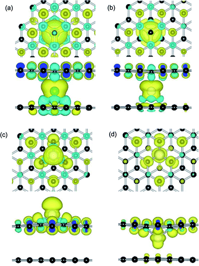
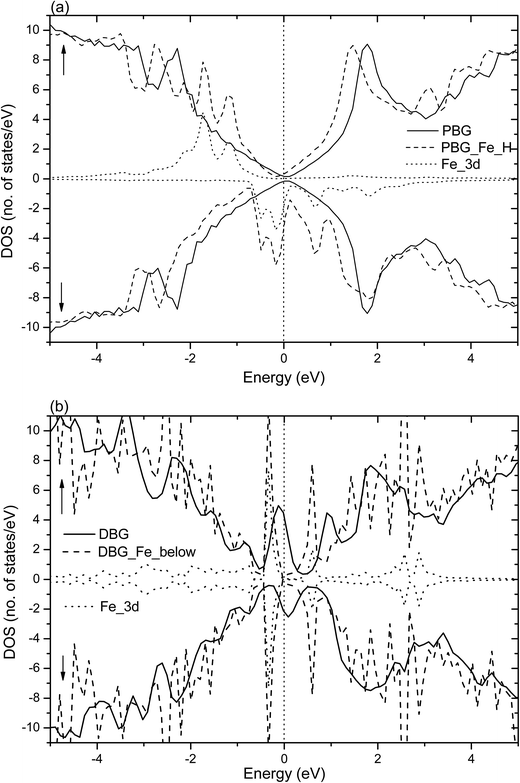
Dopant atoms can modify the graphene system by regulating the electronic structure or injecting charge into the electronic system of sp2-bonded graphene.55 Herein, we investigate the spin charge density (SCD) for the most optimized configuration of the PBG–M and DBG–M systems, as depicted in Fig. 5, where the corresponding contour lines in plots are drawn at 0.001 e Å−3 intervals. As shown in Fig. 5(a) and (b), it is found that the intercalated Fe and Co atom within PBG sheets (H site) induce the spin charge redistribution at their interface. The more electrons dominantly accumulate in the vicinity of C–Fe and C–Co interfaces, the fewer electrons are located on the bottom graphene layer. It is clearly shown that the spin charge distribution of PBG–Fe system is larger than that of the PBG–Co, thus the PBG–Fe system has the large magnetic moment (2.4 μB). As shown in Fig. 6(a), the strong hybridization between the TDOS of PBG system and PDOS of Fe 3d states induce one DOS peak at the EF and the asymmetry of spin channels illustrate that the PBG–Fe system exhibits the magnetic property. Compared with the bare DBG system, the Fe adatom induces the large shifts in the DOS plots and the DOS peaks of DBG system disappear at the EF, as shown in Fig. 6(b). Besides, the symmetric spin channels of DBG–Fe system exhibits nonmagnetic property. Therefore, the electronic structure and magnetic property of graphene sheets can be regulated by choosing different metal atoms. Furthermore, the DOS plots for PBG and DBG systems with the adsorbed Fe atom are investigated through the PBE+U calculation, as shown in Fig. S2(c) and (d).† It is found that the asymmetric spin channels of PBG–Fe or symmetric spin channels of DBG–Fe system exhibits the magnetic or nonmagnetic property, and the strongly hybridize between PDOS of Fe 3d states and TDOS of graphene systems, which is in accordance with the PBE results. In all, an important character in the DOS plots is that the broadened 3d states of metal atoms strongly hybridize with the TDOS of PBG and DBG, illustrating that the d shell electrons play a vital role in enhancing the adatom-graphene interaction.
Compared with the PBG–Co system, these is less spin electrons distribution between the Co atom and DBG sheets (upper and below SV site), as shown in Fig. 5(c) and (d). Although the electrons still mainly accumulate in the vicinity of Co and DBG interfaces, the more electrons are transferred from the Co adatom to DBG and the formation of paired electrons reduce the magnetic property of system, resulting in the magnetism of DBG–Co system is changed from 0.6 to 0.3 μB. In addition, the magnetic moment of Ni atom on PBG and DBG substrates is reduced from 2.0 to 0 μB, thus the adsorbed Co and Ni atoms on graphene substrates exhibit the change of magnetic property. Noting that the Fe adatom on PBG substrate exhibits large magnetic property, yet the DBG–Fe system exhibits the nonmagnetic materials. Based on the Bader charge analysis,45 the number of electrons (Δq, e) are transferred from the metal adatoms to the PBG (or DBG) substrates, as shown in Table 3. It is found that the more transferred electrons move from Fe atom to graphene sheets as compared with other metal atoms (Co, Ni and Cu). Compared with metal adatoms on PBG substrates, the metal doping provide the more electrons and thus exhibit the more positively charged, which may regulate the surface activity of graphene sheet.38
| Adatom | Substrates | |||||||
|---|---|---|---|---|---|---|---|---|
| PBG | DBG | |||||||
| Top | Bottom | Upper | Below | |||||
| Δq (e) | m (μB) | Δq (e) | m (μB) | Δq (e) | m (μB) | Δq (e) | m (μB) | |
| Fe | 0.84 | 2.1 (H) | 0.93 | 2.4 (H) | 1.07 | 0.0 | 1.14 | 0.0 |
| Co | 0.71 | 1.3 (H) | 0.77 | 1.4 (H) | 0.73 | 0.6 | 0.85 | 0.3 |
| Ni | 0.55 | 0.0 (H) | 0.59 | 0.0 (B) | 0.72 | 0.0 | 0.82 | 0.0 |
| Cu | 0.24 | 0.6 (T) | 0.69 | 0.0 (B) | 0.65 | 0.9 | 0.75 | 0.8 |
3.3 Migration pathways and energy barriers
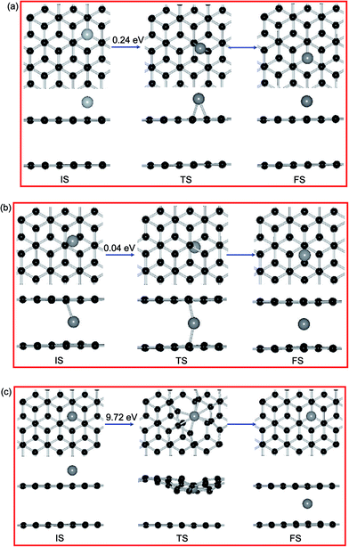
NEB calculations investigate that the diffusion pathways for Ni adatom on PBG substrates, as shown in Fig. 7. Previous results shown that a single Ni adatom can easily diffuse on the PMG sheet with an energy barrier (Ebar) of 0.21 eV,38 the corresponding diffusion pathways between equilibrium states (from the H site to the next one). As shown in Fig. 7(a), the Ni adatom on the top layer of PBG substrate has a slightly large Ebar of 0.24 eV from H site to a neighboring one and the neighboring B site is viewed as the TS, which is similar as that on the PMG surface. Besides, the diffusion pathway of Ni adatom on the bottom layer of PBG are also investigated, along with the reaction pathways B → T → B, as shown in Fig. 7(b). It is found that the Ni adatom has much smaller Ebar (0.04 eV) than that on the PMG and PBG sheets, indicating that the intercalated Ni atom is more inclined to diffuse and accumulate within graphene overlayer.
For the intercalated processes of metal adatom on PBG substrates, the corresponding diffusion pathways are also investigated, which is allows us to understand whether the penetration mechanism is connected to the structural morphology of supported substrate. For the Ni adatom on PBG surface, we select the most stable H site for Ni adatom on upper layer as an IS, as shown in Fig. 7(c). We let a Ni atom goes through by the breaking C–C bonds downward and penetrates into graphene overlayer, then the anchored Ni atom at the T site of bottom layer is viewed as FS. The energy barrier of the TS along the reaction pathway is estimated to be 9.72 eV, which is extremely large and is more difficult to overcome. Table 4 shows that the diffusion processes of metal adatoms from the top layer to bottom layer have much larger energy barriers (>7.0 eV) than those on the PMG and PBG substrates, indicating that it is hardly possible for metal adatom penetrates into graphene from the pristine surface.
| Adatom | Substrates | ||||
|---|---|---|---|---|---|
| PBG | DBG | ||||
| Top | Bottom | Top–bottom | Below-SV | Upper-below | |
| Fe | 0.42 eV (H–H) | 0.13 eV (T–H) | 7.71 eV (H–T) | 3.81 eV | 3.05 eV |
| Co | 0.50 eV (H–H) | 0.20 eV (H–H) | 9.29 eV (H–T) | 3.74 eV | 2.88 eV |
| Ni | 0.24 eV (H–H) | 0.04 eV (B–B) | 9.72 eV (H–T) | 3.11 eV | 2.06 eV |
| Cu | 0.14 eV (T–T) | 0.07 eV (B–B) | 11.05 eV (H–T) | 1.90 eV | 1.50 eV |
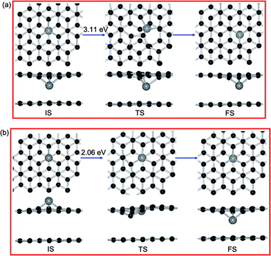
Furthermore, we let the Ni atom moves from the upper SV site into graphene overlayer and the corresponding diffusion pathway is shown in Fig. 8(b). The calculated energy barrier in this situation is 2.06 eV, which is smaller than the surface diffusion of Ni dopant (3.11 eV) and the intercalated Ni atom from top layer to the bottom layer (9.72 eV). This result indicated that the Ni adatom tends to go through the SV site and intercalated into the graphene sheets. For other metal dopants, the corresponding order of Ebar is Fe (3.05 V) > Co (2.88 V) > Ni (2.06 V) > Cu (1.50 V), which is in accordance with the diffusion trend of metal dopants in DBG sheets. Hence, the broken C–C bonds within graphene react with a metal adatom and then form metal dopant in graphene overlayer, which may explain the presence of metallic impurity in graphite. As shown in Tables 3 and 4, the more electrons are transferred from metal dopants to DBG sheets than those on PBG substrate, which is connected to the strength of adsorbates–substrates interaction and their diffusion barriers.
Comparing the different diffusion pathways and energy barriers, it is found that the metal adatoms on bottom layer of PBG have smaller diffusion barriers (0.04–0.20 eV) than that on the top layer, illustrating that the metal adatoms within graphene sheets tend to accumulate and form the metal cluster. For the PBG sheets, the intercalation reaction of metal atom need to overcome the large energy (>7.0 eV) from the upper layer into the sublayer, so it is quite difficult to penetrate into PBG sheets through pristine surface. In comparison, the metal adatom on DBG sheets possibly penetrate into sublayer through the SV site with the relatively small energy barriers. These results indicate that the defective structure not only can enhance the stability of metal adatom, but also can facilitate the metal intercalation process. In all, the presence of metal substrate can regulate the stability of metal atoms on graphene sheets, and the transferred electrons can turn the electronic structure and magnetic property of adsorbate–substrate systems. Therefore, the metal adatoms are anchored on PBG and DBG sheets have a profound effect on the potential applications for graphene-based composites as the catalytic, electronic and spintronic devices.
4. Conclusions
Employing density functional theory, we study the adsorption behaviors of different metal adatoms (Fe, Co, Ni and Cu) on PMG and PBG sheets, with the aim of studying the adsorbed metal atoms induce the change in electronic structure and magnetic property of graphene sheets. Our study reveal that the covalent bonds character between metal adatoms and graphene substrates and the metal adatoms on DBG systems are more stable than that on the PBG. Besides, the adsorbed Fe, Co and Cu atoms on PBG and DBG substrates can exhibit the varied magnetic moments, while the Ni adatom on PBG (or DBG) system is nonmagnetic property. Compared with the isolated graphene sheets, the Pt(111) supported graphene substrates have some effect on the stability of metal adatoms and the metal dopants at SV sites are still more stable than that on pristine sheet. Moreover, the present study quantitatively how metal atoms diffusion on graphene surface. It is found that the metal adatoms have small energy barriers within PBG sheets and tend to aggregate. For the intercalation reaction within graphene sheets, it is more difficult for metal adatoms move into sublayer from the pristine surface, yet the more favorable reaction pathway for metal atoms go through the defective site and penetrate into graphene sheets. These results provide the valuable reference for designing the new functional metal–graphene devices.Acknowledgements
This work was supported by the National Natural Science Foundation of China (Grant No. U1404109, 11504334, 11791240177 and 61674053), the Natural Science Foundation of Henan Province (Grant No. 162300410325) and the Application Foundation and Advanced Technology Research Program of Henan Province (Grant No. 152300410167).References
- S. Stankovich, D. Dikin, G. Dommett, K. Kohlhaas, E. Zimney, E. Stach, R. Piner, S. Nguyen and R. Ruoff, Nature, 2006, 442, 282–286 CrossRef CAS PubMed.
- M. F. El-Kady, V. Strong, S. Dubin and R. B. Kaner, Science, 2012, 335, 1326–1330 CrossRef CAS PubMed.
- N. G. Sahoo, Y. Pan, L. Li and S. H. Chan, Adv. Mater., 2012, 24, 4203–4210 CrossRef CAS PubMed.
- M. Ugeda, D. Fernández-Torre, I. Brihuega, P. Pou, A. Martínez-Galera, R. Pérez and J. Gómez-Rodríguez, Phys. Rev. Lett., 2011, 107, 116803 CrossRef CAS PubMed.
- X. Shen, H. Wang and T. Yu, Nanoscale, 2013, 5, 3352–3358 RSC.
- Q. Tang, Z. Zhou and Z. Chen, Nanoscale, 2013, 5, 4541–4583 RSC.
- A. Krasheninnikov, P. Lehtinen, A. Foster, P. Pyykkö and R. Nieminen, Phys. Rev. Lett., 2009, 102, 126807 CrossRef CAS PubMed.
- O. Cretu, A. V. Krasheninnikov, J. A. Rodríguez-Manzo, L. Sun, R. M. Nieminen and F. Banhart, Phys. Rev. Lett., 2010, 105, 196102 CrossRef PubMed.
- E. J. G. Santos, A. Ayuela and D. Sanchez-Portal, New J. Phys., 2010, 12, 053012 CrossRef.
- H. Wang, Q. Wang, Y. Cheng, K. Li, Y. Yao, Q. Zhang, C. Dong, P. Wang, U. Schwingenschlögl, W. Yang and X. X. Zhang, Nano Lett., 2012, 12, 141–144 CrossRef CAS PubMed.
- A. W. Robertson, B. Montanari, K. He, J. Kim, C. S. Allen, Y. A. Wu, J. Olivier, J. Neethling, N. Harrison and A. I. Kirkland, Nano Lett., 2013, 13, 1468–1475 CrossRef CAS PubMed.
- Z. He, K. He, A. W. Robertson, A. I. Kirkland, D. Kim, J. Ihm, E. Yoon, G.-D. Lee and J. H. Warner, Nano Lett., 2014, 14, 3766–3772 CrossRef CAS PubMed.
- A. Ambrosi, S. Y. Chee, B. Khezri, R. D. Webster, Z. Sofer and M. Pumera, Angew. Chem., Int. Ed., 2012, 51, 500–503 CrossRef CAS PubMed.
- J. R. Miller, R. Outlaw and B. Holloway, Science, 2010, 329, 1637–1639 CrossRef CAS PubMed.
- E. McCann and M. Koshino, Rep. Prog. Phys., 2013, 76, 056503 CrossRef PubMed.
- C.-H. Hsu, W.-H. Lin, V. Ozolins and F.-C. Chuang, Appl. Phys. Lett., 2012, 100, 063115 CrossRef.
- Y. Mao, G. M. Stocks and J. Zhong, New J. Phys., 2010, 12, 033046 CrossRef.
- R. Nouchi, Appl. Phys. Lett., 2014, 105, 223106 CrossRef.
- Y. Mao, Z. Xie, J. Yuan, S. Li, Z. Wei and J. Zhong, Phys. E, 2013, 49, 111–116 CrossRef CAS.
- Y. Mao and J. Zhong, Nanotechnology, 2008, 19, 205708 CrossRef PubMed.
- D. Nafday and T. Saha-Dasgupta, Phys. Rev. B: Condens. Matter Mater. Phys., 2013, 88, 205422 CrossRef.
- X. Liu, Y. Han, J. W. Evans, A. K. Engstfeld, R. J. Behm, M. C. Tringides, M. Hupalo, H.-Q. Lin, L. Huang, K.-M. Ho, D. Appy, P. A. Thiel and C.-Z. Wang, Prog. Surf. Sci., 2015, 90, 397–443 CrossRef CAS.
- J. Zheng, Y. Wang, L. Wang, R. Quhe, Z. Ni, W.-N. Mei, Z. Gao, D. Yu, J. Shi and J. Lu, Sci. Rep., 2013, 3, 2081 CrossRef PubMed.
- Q. Wang, L. Wei, M. Sullivan, S.-W. Yang and Y. Chen, RSC Adv., 2013, 3, 3046–3053 RSC.
- M. Jiao, K. Li, Y. Wang and Z. Wu, J. Phys. Chem. C, 2015, 119, 12643–12650 CAS.
- W. Chen, P. Cui, W. Zhu, E. Kaxiras, Y. Gao and Z. Zhang, Phys. Rev. B: Condens. Matter Mater. Phys., 2015, 91, 045408 CrossRef.
- K. McCreary, K. Pi, A. Swartz, W. Han, W. Bao, C. Lau, F. Guinea, M. Katsnelson and R. Kawakami, Phys. Rev. B: Condens. Matter Mater. Phys., 2010, 81, 115453 CrossRef.
- M. Hupalo, S. Binz and M. Tringides, J. Phys.: Condens. Matter, 2011, 23, 045005 CrossRef CAS PubMed.
- P. Sutter, J. T. Sadowski and E. A. Sutter, J. Am. Chem. Soc., 2010, 132, 8175–8179 CrossRef CAS PubMed.
- X. Liu, C. Z. Wang, M. Hupalo, W. C. Lu, M. C. Tringides, Y. X. Yao and K. M. Ho, Phys. Chem. Chem. Phys., 2012, 14, 9157–9166 RSC.
- X. Liu, C. Z. Wang, Y. X. Yao, W. C. Lu, M. Hupalo, M. C. Tringides and K. M. Ho, Phys. Rev. B: Condens. Matter Mater. Phys., 2011, 83, 235411 CrossRef.
- P. Sutter, J. T. Sadowski and E. Sutter, Phys. Rev. B: Condens. Matter Mater. Phys., 2009, 80, 245411 CrossRef.
- G. Giovannetti, P. Khomyakov, G. Brocks, V. Karpan, J. Van den Brink and P. Kelly, Phys. Rev. Lett., 2008, 101, 026803 CrossRef CAS PubMed.
- S. Ulstrup, L. Nilsson, J. A. Miwa, R. Balog, M. Bianchi, L. Hornekær and P. Hofmann, Phys. Rev. B: Condens. Matter Mater. Phys., 2013, 88, 125425 CrossRef.
- Y. N. Tang, Z. X. Yang and X. Q. Dai, J. Chem. Phys., 2011, 135, 224704 CrossRef PubMed.
- Y. Tang, W. Chen, C. Li, W. Li and X. Dai, J. Phys.: Condens. Matter, 2015, 27, 255009 CrossRef PubMed.
- P. Wu, X. Zhai, Z. Li and J. Yang, J. Phys. Chem. C, 2014, 118, 6201–6206 CAS.
- Y. Tang, X. Dai, Z. Yang, Z. Liu, L. Pan, D. Ma and Z. Lu, Carbon, 2014, 71, 139–149 CrossRef CAS.
- I. Klimovskikh, S. Tsirkin, A. Rybkin, A. Rybkina, M. Filianina, E. Zhizhin, E. Chulkov and A. Shikin, Phys. Rev. B: Condens. Matter Mater. Phys., 2014, 90, 235431 CrossRef.
- G. Kresse and J. Furthmüller, Comput. Mater. Sci., 1996, 6, 15–50 CrossRef CAS.
- G. Kresse and J. Furthmüller, Phys. Rev. B: Condens. Matter Mater. Phys., 1996, 54, 11169–11186 CrossRef CAS.
- G. Kresse and D. Joubert, Phys. Rev. B: Condens. Matter Mater. Phys., 1999, 59, 1758–1775 CrossRef CAS.
- J. Perdew, K. Burke and M. Ernzerhof, Phys. Rev. Lett., 1996, 77, 3865–3868 CrossRef CAS PubMed.
- J. Carlsson and M. Scheffler, Phys. Rev. Lett., 2006, 96, 46806 CrossRef PubMed.
- G. Henkelman, A. Arnaldsson and H. Jónsson, Comput. Mater. Sci., 2006, 36, 354–360 CrossRef.
- G. Henkelman, B. Uberuaga and H. Jónsson, J. Chem. Phys., 2000, 113, 9901–9904 CrossRef CAS.
- G. Henkelman and H. Jónsson, J. Chem. Phys., 2000, 113, 9978–9985 CrossRef CAS.
- T. Zhu, J. Li and S. Yip, Phys. Rev. Lett., 2004, 93, 25503 CrossRef PubMed.
- T. P. Hardcastle, C. R. Seabourne, R. Zan, R. M. D. Brydson, U. Bangert, Q. M. Ramasse, K. S. Novoselov and A. J. Scott, Phys. Rev. B: Condens. Matter Mater. Phys., 2013, 87, 195430 CrossRef.
- H. Johll, H. C. Kang and E. S. Tok, Phys. Rev. B: Condens. Matter Mater. Phys., 2009, 79, 245416 CrossRef.
- K. Chan, J. Neaton and M. Cohen, Phys. Rev. B: Condens. Matter Mater. Phys., 2008, 77, 235430 CrossRef.
- Y. Tang, Z. Yang and X. Dai, Phys. Chem. Chem. Phys., 2012, 14, 16566–16572 RSC.
- X. Dai, Y. Tang, J. Zhao and Y. Dai, J. Phys.: Condens. Matter, 2010, 22, 316005 CrossRef PubMed.
- T. Ohta, A. Bostwick, T. Seyller, K. Horn and E. Rotenberg, Science, 2006, 313, 951–954 CrossRef CAS PubMed.
- F. Banhart, J. Kotakoski and A. V. Krasheninnikov, ACS Nano, 2011, 5, 26–41 CrossRef CAS PubMed.
- Y. N. Tang, Z. X. Yang and X. Q. Dai, J. Magn. Magn. Mater., 2011, 323, 2441–2447 CrossRef CAS.
- Y. J. Gan, L. T. Sun and F. Banhart, Small, 2008, 4, 587–591 CrossRef CAS PubMed.
- Q. G. Jiang, Z. M. Ao, S. Li and Z. Wen, RSC Adv., 2014, 4, 20290–20296 RSC.
Footnote |
| † Electronic supplementary information (ESI) available. See DOI: 10.1039/c7ra04519k |
| This journal is © The Royal Society of Chemistry 2017 |

