 Open Access Article
Creative Commons Attribution 3.0 Unported Licence
Poly(vinylidene fluoride) grafted polystyrene (PVDF-g-PS) membrane based on in situ polymerization for solvent resistant nanofiltration†
Fang Yuan,
Yi Yang,
Rui Wang and
Dongju Chen *
*
School of Chemistry and Chemical Engineering, Liaoning Normal University, Huanghe Road 850, Dalian 116029, P. R. China. E-mail: dongju.chen@yahoo.com
First published on 30th June 2017
Abstract
A poly(vinylidene fluoride) grafted polystyrene (PVDF-g-PS) solvent resistant nanofiltration membrane (SRNF) was designed and prepared. A PVDF porous membrane was firstly prepared by phase inversion in a non-solvent bath. PS was grafted onto the PVDF porous membrane to form a PVDF-g-PS nanofiltration membrane. The influence of grafting degree and concentration of the casting solution on the morphology of the membranes was investigated by Scanning Electron Microscopy (SEM). Separation performance was evaluated by filtering three different dyes: Rose Bengal (RB), Acid Fuchsin (AF) and Bromothymol Blue (BTB) using water, ethanol and IPA as solvents. The RB retentions of the PVDF-g-PS20 membrane in water, ethanol and IPA could reach 92.3%, 91.2% and 90% respectively. The RB retentions in water, ethanol and IPA of the PVDF-g-PS20 membrane were all higher than 90%, both in aqueous and organic solvent systems. All the results showed that the graft porous membrane was very promising for SRNF.
Introduction
Over the past years, solvent resistant nanofiltration (SRNF) has experienced increasing attention, as it holds a wide potential for novel applications in the fine chemicals, pharmaceutical, food and petrochemical industries.1–5 Pressure driven membrane processes have been widely used in aqueous systems, such as, reverse osmosis (RO), nanofiltration (NF) and microfiltration (MF). However, membrane separations in non-aqueous systems (organic solvents) are just starting to become exploited, showing huge potential.6–8 The membrane processes used in non-aqueous systems could offer considerable energy savings and their easy integration in existing unit operations renders SRNF economically viable.9,10 For membranes to be useful in SRNF, a high chemical stability is needed.11,12 Therefore, a lot of research focuses on the development of new membrane materials that would meet these requirements.13–15PVDF is a semi-crystalline polymer, which is well-known for being thermally stable, possessing a high mechanical strength, low surface energy and an excellent resistance to most corrosive chemicals and organic compounds. PVDF has thus been widely used to fabricate porous membranes, used in a variety of industrial applications.16–19 They are commonly prepared via the phase inversion technique.20–23 And the resulted porous PVDF membranes show very good chemical stability and mechanical properties.24,25 However, for the best of our knowledge, PVDF has so far seldom been used as NF membrane probably due to its high hydrophobicity, which limits its use for aqueous applications. Nevertheless, due to its intrinsic excellent chemical resistance, mechanical strength and thermal stability, it could be an excellent candidate for preparation of SRNF-membrane. As found in preliminary experiments, the main challenge in fabricating a SRNF membrane from PVDF is to reduce the ‘pore size’ in the selective layer down to the NF range. Copolymers, like poly(vinylidene fluoride-trifluoroethylene) (P(VDF-TrFE)),26 poly(vinylidene fluoride-co-chlorotrifluoroethylene)-P(VDF-CTFE)27 have been developed to obtain more specific properties to meet the specific requirements of novel application areas. The morphology, hydrophobicity, thermal and mechanical properties of these copolymers can be well-controlled by different phase separation (NIPS) technique,28 which was easy to operate.
Grafting is one of the most efficient ways to improve the properties of membranes.29–34 Qiu reported that permanent hydrophilicity was achieved by grafting styrene/maleic anhydride copolymer (SMA) on PVDF membrane surfaces.35 Freger et al. grafted acrylic acid (AA) monomers onto polyamide membranes to improve the anti-fouling properties of polyamide membranes.36 Li et al. studied ultrafiltration (UF) membranes consisting of polystyrene grafted onto polyacrylonitrile matrix via low-temperature plasma in the vapor phase. The graft modification improved the hydrophobicity of the membrane surface and increased both flux and rejection.37
We now report the use of radical graft polymerization with redox initiation to convert a UF PVDF-membrane to a SRNF-membrane. The porous PVDF membrane was prepared via phase inversion,20–23 after which the PVDF-g-PS membrane was obtained by grafting styrene as the monomer using benzoyl peroxide (BPO) as the initiator. The separation layer of the PVDF-g-PS membrane thus became dense enough to realize rejections in the SRNF range.
Experimental
Materials
PVDF powder (Mw = 534![[thin space (1/6-em)]](https://www.rsc.org/images/entities/char_2009.gif) 000 Da) and benzoyl peroxide (BPO) was purchased from Sigma-Aldrich Ltd. Styrene was purchased from Acros and used without any further purification. Bengal rose (Mw = 973.67 Da), acid fuchsin (Mw = 585.54 Da) and bromothymol blue (Mw = 646.37) were used as dyes. N-Methyl Pyrrolidinone (NMP), tetrahydrofuran (THF), chloroform, ethanol and isopropanol (IPA) were obtained from Tianjin Damao Chemical Reagent Factory as analytical grade.
000 Da) and benzoyl peroxide (BPO) was purchased from Sigma-Aldrich Ltd. Styrene was purchased from Acros and used without any further purification. Bengal rose (Mw = 973.67 Da), acid fuchsin (Mw = 585.54 Da) and bromothymol blue (Mw = 646.37) were used as dyes. N-Methyl Pyrrolidinone (NMP), tetrahydrofuran (THF), chloroform, ethanol and isopropanol (IPA) were obtained from Tianjin Damao Chemical Reagent Factory as analytical grade.
Membrane preparation
The starting membranes were prepared from PVDF/NMP/THF solutions by phase inversion.38 The solution was cast with a 250 μm wet thickness by using a lab-made casting knife and immersed into deionized water for about 15 min. All membranes were washed three times with ethanol in order to remove the water trapped in the pores before immersing into a KOH/ethanol solution which eliminate some of the H and F atoms from the PVDF to generate double bonds, which will form the grafting point in the next step preparation. The concentration of the KOH/alcohol solution was 0.1 M and the membranes were immersed for 30, 90, 150 and 210 minutes. The membranes were then washed several times with deionized water until a constant pH was reached before immersing them into the grafting solution. This solution contained 80 vol% volume styrene and 20 vol% THF, and the radical initiator BPO with a concentration of 3 × 10⁻³ g mL−1. The grafting reaction was performed at 80 °C for 8, 16, 24 and 32 hours. The membrane was extracted with chloroform to remove unreacted monomer and uncoupled homopolymer.Mechanical stability
The mechanical stability of membranes was determined by a material test-machine (AG-2004, Shimadzu) at a loading velocity of 5 cm min−1. Each result was an average value of at least three parallel experiments.Water contact angle
The water contact angle was measured by a sessile drop method (JC2001A, POWER-EACH®, China). The image was frozen as soon as 10 μL deionized water was dropped onto membrane surface.UV-vis and ATR-IR
UV-vis was recorded on a double-beam UV-vis spectrophotometer (TU-1901). Attenuated total reflectance (ATR) infrared spectra were obtained by using a BRUKE TENSOR 27 spectrophotometer. Infrared spectra (IR) were recorded over the range from 3100 to 500 cm−1 (average of 64 scans at 4 cm−1 resolution).Scanning electron microscope (SEM) and field emission scanning electron microscope (FESEM)
The surfaces and cross-sections of membranes were observed with scanning electron microscopy (SEM) using a Philips XL30 FEG scanning electron microscope, i.e. a semi-in-lens type microscope with a cold field emission electron source. The cross-sections were obtained after breaking the membranes in liquid nitrogen. FESEM was carried out on a Philip XL-30-ESEM-FEG to investigate the morphology of the membranes. To reduce sample charging under the electron beam, the samples were coated with a thin gold layer by using a Cressington HR208 high resolution sputter coater for 2 min at 20 mA to render them conductive.Membrane performance
 | (1) |
The retention values (R) were calculated by:
 | (2) |
Where Cf and Cp are the concentration of the feed and the permeate respectively. The concentration of the feed solution was 35 μM.
All retention results are average values based on at least three distinct samples. The standard deviation on the measurements was within 5%. All measurements were carried out on single dye solutions.
Results and discussion
Fig. 1 shows the ATR-FTIR spectra of PVDF and PVDF-g-PS membranes. Several new bands appeared only in the modified membrane spectra and are attributed to the benzene group of the styrene monomer. The band at 699 cm−1 is due to the in-plane CH-bending vibration of the substituted benzene ring. The bands close to 1601 cm−1 and 1493 cm−1 can be ascribe to the in-plane stretching vibration of the benzene ring, and the 2930 cm−1 and 2850 cm−1 bands are due to the asymmetric and symmetric stretching vibrations of CH2, respectively.40 These data confirm that the styrene has been successfully grafted on the PVDF membrane. The β-phase content of the prepared PVDF membranes, calculated from ATR-FTIR result according to a previous report,28 were 0.47 for PVDF, 0.59 for PVDF-g-PS12, 0.595 for PVDF-g-PS16 and 0.746 for PVDF-g-PS20, respectively.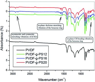 | ||
| Fig. 1 ATR-IR spectra of PVDF and PVDF-g-PS series membranes. PVDF-g-PS membrane prepared from PVDF casting solution contains 12% PVDF (PVDF12), 16% PVDF (PVDF16) and 20% PVDF (PVDF20). | ||
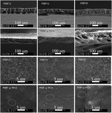
SEM images indicated the effect of solution concentration the morphology of membranes before and after modification. From Fig. 2, it is clear that the separation layer and sub-morphology of PVDF and PVDF-g-PS membranes change with the casting film concentration. As solution concentration increases, the sub-morphology becomes less interconnected. The influence of grafting on the membrane surface can be observed in Fig. 2. After graft polymerization with styrene, the membrane pores disappear and the surfaces of the PVDF membranes is covered with the newly grafted layer. Fig. 2 gives the detailed information of cross-sections of PVDF and PVDF-g-PS membranes. It is less obvious to observe the PS coating on the pore walls than on the membrane surface.
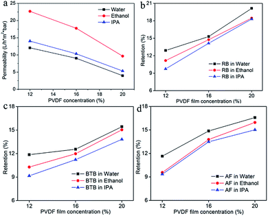
Three different types of porous PVDF membranes were prepared by phase inversion based on different casting concentrations. The membrane selectivities measured with the dye solutions are presented in Fig. 3 and the permeance was presented in Fig. 3a. The permeance results show that the pores in the selective layer of the PVDF12 membranes are quite open, as was already observed in Fig. 2. This open separation layer leads to very low retentions on the dyes and high solvent permeance with this membrane. Slightly better separation results and comparatively lower permeance were found for PVDF16 and PVDF20. This is because the higher concentration of the casting solution leads to a denser skin layer and smaller pore size,11 as was already seen in Fig. 2.
The porous membrane formation process is influenced by non-solvent/solvent exchange rates, which is the kinetic aspect of the phase inversion process. Under rapid de-mixing conditions, membranes with a macrovoid substructure and thin skin layers can be expected. Membranes prepared under delayed demixing conditions, on the other hand, typically show a dense skin layer and a less interconnected substructure, hence lower porosities.38,41,42 By increasing the initial PVDF concentration, a higher concentration was obtained at the polymer/non-solvent interface when the wet polymer solution film was immersed into the non-solvent coagulant bath. Non-solvent in-diffusion was thus slowed down due to the high viscosity and the demixing was delayed, resulting in denser skin layers as evidenced by SEM results.
In order to develop PVDF membranes for SRNF applications, post-synthesis membrane modifications have been applied in this study. Polystyrene was grafted on the surface of the PVDF membrane to make an active layer with smaller pores. This densification process was thus assumed to improve the separation performance of PVDF membranes to bring the retention of porous PVDF-g-PS membrane to the NF level.
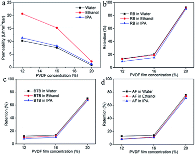
In the following paragraphs, the influence of a selection of casting and graphing parameter was studied. Fig. 4 show the pure solvent permeance (Fig. 4a) and retention results of PVDF-g-PS membranes with pristine PDVF membranes cast from different PVDF concentrations. It was found that the PS grafting proved effective only when the pores of the pristine PVDF-membrane were not too big. Indeed the performance of the PVDF12 membrane and the PVDF-g-PS12 membrane was comparable. This means that the grafting of polystyrene does not significant increase the separation capability of this membrane. For PVDF-g-PS16 membrane, the retentions of RB in water and ethanol slightly increased following grafting (from 15.3% to 20.2% in water, from 14.8% to 19.1% in ethanol) (Fig. 4b). The improved RB retention evidenced that the grafting densification began to influence the separation capabilities of membranes. However, the retentions of the smaller dyes BTB (Fig. 4c) and AF (Fig. 4d) remain the same as the retentions for the PVDF16 membrane. The retentions of dyes increased strongly when the concentration of the casting solution of the PVDF pristine membrane was 20%. The RB retentions of PVDF-g-PS20 membrane in water, ethanol and IPA reached 92.3%, 91.2% and 90% respectively, while the other two dyes also became better retained. The retentions of BTB are higher than 65% and the retentions of AF are higher than 70% in all solvents used.
Since the grafting condition was the same for the PVDF12, PVDF16 and PVDF20 membranes, it is reasonable to believe that all three membranes have a similar degree of grafting. In this case, a different performance of the fabricated SRNF membranes is probably a consequent of the physicochemical difference of the pristine membrane. Since all pristine membranes were PVDF, it can be assumed that the different in the surface morphology i.e., the MWCO or the active layer of the pristine membrane, is the main parameter that influences the grafted membrane performance.
The PVDF12-g-PS thus did not result in a SRNF membrane. As the skin layer pore size of the PVDF12 membrane was quite large as discovered on the SEM image, even after grafting, the pores size of PVDF-g-PS12 membranes was still not small enough to bring the separation performance to the NF range. Compared with the PVDF12 and PVDF16 membranes, the original pores in the PVDF20 membrane were the narrowest one. Based on this denser separation layer, it was possible to decrease the pore sizes enough to obtain NF-performance (Scheme 1). The RB retentions in water, ethanol and IPA of PVDF-g-PS20 membrane were all higher than 90%, both in aqueous and inorganic solvent systems. These membranes can thus be truly considered as SRNF-types. The retentions of dyes with lower MW, BTB and AF, increase strongly as well: the BTB retentions are higher than 65% and the retentions of AF higher than 70%. The morphology changes and the separation properties of pore filled PVDF-g-PS series membranes are illustrated in Schemes 1 and 2.
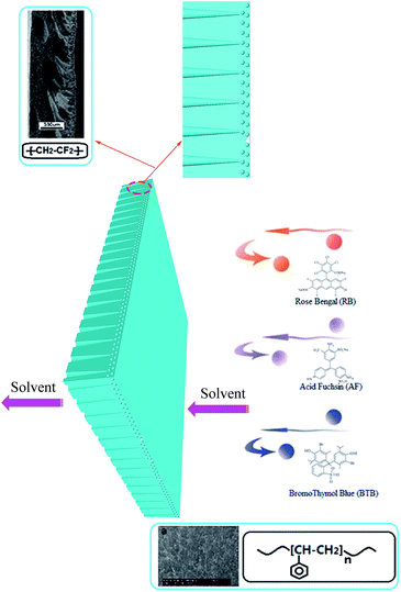 | ||
| Scheme 2 Schematic illustration of the morphology and the separation properties of pore filled PVDF-g-PS membranes. | ||
The membrane hydrophilicity is an important factor in determining membrane performance. Water contact angle was performed to investigate the effect of grafting time of PS on the hydrophilicity of PVDF membrane. The water contact angle value decreases from 91° to 78.5° from origin PVDF (20) membrane to PVDF (20) treated with KOH for 150 minutes and then grafted for 32 h (Fig. S2†). The decrease of water contact is resulted from enhancement of membrane hydrophilicity brought by PS grafting on membrane surface and in the pores, leading to the lower surface free energy of original hydrophobic PVDF (20) membrane.
As known in literature and from Fig. 4, it is noted that the retention of a specific solute is different in the three solvents.43 For each dye, the retention is the highest when water is used as solvent and the lowest with IPA as solvent. The same trends are also observed for BTB and AF.
Adequate mechanical properties are essential for the use of the membranes in SRNF.27 Thus the mechanical properties of prepared membranes (PVDF (20), PVDF (20) treated with KOH for 150 minutes, PVDF (20) treated with KOH for 150 minutes and then grafted for 8 h, 16 h, 24 h and 32 h) were detected and as displayed in Fig. S1.† Normally the mechanical stability of membranes will decrease after radiation grafting modification. To our surprise, the tensile strength of the modified PVDF membranes showed no obvious changing, while the elongation ratio increase simultaneously after modification. This phenomenon is probably due to PS grafting on the whole membrane which decreased the porosity and pore size, resulting better membrane rigidity and tenacity.
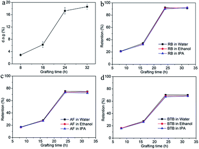
The influence of grafting time on the performance of a PVDF-g-PS membrane was investigated. The PVDF20 membrane was chosen because it showed separation performance at the NF level after grafting. The membranes resided in the grafting solution for 8 h (PVDF-g-PS8h), 16 h (PVDF-g-PS16h), 24 h (PVDF-g-PS24h), and 32 h (PVDF-g-PS32h), respectively. Different grafting times led to different degrees of grafting (d.o.g.). The degree of grafting (d.o.g.) was determined gravimetrically, according to the following equation:
 | (3) |
Fig. 5a shows the relationship between the d.o.g. and the grafting time. The d.o.g. increased from 5.6% (16 h) to 18% (24 h), which showed that the grafting process mainly happened after 16 h. Fig. 5a also showed that the d.o.g. did not increase after 24 hours. The separation performances and permeances shown in Fig. 5b–d show that the permeance decreased with increasing grafting time, while retentions increased steadily. A longer grafting time led to denser membrane. Compared with PVDF20 membrane, the retentions of dyes of PVDF-g-PS8h and PVDF-g-PS16h membranes were at the same level, due to the insufficient d.o.g. of membranes. The surface of the membrane with lower d.o.g. was thus not dense enough to retain the dye molecules. The retention of RB reached 90% when PVDF-g-PS24h was used, of which the d.o.g. was 21%. The RB retention of PVDF-g-PS32h membrane was the same as PVDF-g-PS24 membrane, in agreement with their comparable d.o.g. AF and BTB retentions also increased to more than 70% and 67% respectively.
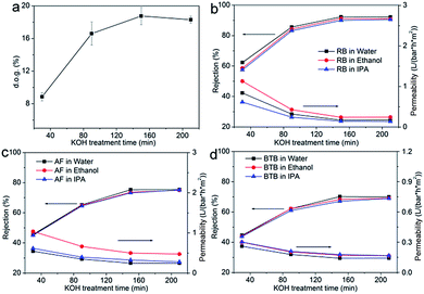
The influence of KOH treatment time was also investigated by using PVDF20 membrane as pristine membrane. The d.o.g. is shown in Fig. 6a. When the PVDF membrane was immersed in the KOH solution, H and F were eliminated from the PVDF chains. At the same time, –(CH![[double bond, length as m-dash]](https://www.rsc.org/images/entities/char_e001.gif) CF)n– and –[C(OH)
CF)n– and –[C(OH)![[double bond, length as m-dash]](https://www.rsc.org/images/entities/char_e001.gif) CH–C(O)–CH
CH–C(O)–CH![[double bond, length as m-dash]](https://www.rsc.org/images/entities/char_e001.gif) CH–C(OH)–CH–C(O)–CH
CH–C(OH)–CH–C(O)–CH![[double bond, length as m-dash]](https://www.rsc.org/images/entities/char_e001.gif) CH–(OF)–]n were formed.41,44 BPO subsequently produced active sites at the –C
CH–(OF)–]n were formed.41,44 BPO subsequently produced active sites at the –C![[double bond, length as m-dash]](https://www.rsc.org/images/entities/char_e001.gif) C– substrate site and styrene molecules could easily be grafted onto PVDF membranes. PVDF20 membrane was chosen as pristine membrane and 30 minutes (PVDF-g-PS30m), 90 minutes (PVDF-g-PS90m), 150 minutes (PVDF-g-PS150m) and 210 minutes (PVDF-g-PS210m) as KOH treatment times were chosen. As expected, the longer KOH treatment time produced more sites for reaction which led to more styrene grafted onto the membrane. As the KOH treatment time lasted longer, the d.o.g. increased from 9.2% to 18%. The retention and permeance are shown in Fig. 6b–d. The more densified surfaces led to lower solvent permeances and higher dye rejections. The retention of RB in water increased from 62%, after 30 minutes of KOH treatment, to 92%, after 90 minutes. The same trend was also observed when different solvents were used. The d.o.g. didn't increase anymore after 150 minutes treatment time in KOH, which meant that no more –C
C– substrate site and styrene molecules could easily be grafted onto PVDF membranes. PVDF20 membrane was chosen as pristine membrane and 30 minutes (PVDF-g-PS30m), 90 minutes (PVDF-g-PS90m), 150 minutes (PVDF-g-PS150m) and 210 minutes (PVDF-g-PS210m) as KOH treatment times were chosen. As expected, the longer KOH treatment time produced more sites for reaction which led to more styrene grafted onto the membrane. As the KOH treatment time lasted longer, the d.o.g. increased from 9.2% to 18%. The retention and permeance are shown in Fig. 6b–d. The more densified surfaces led to lower solvent permeances and higher dye rejections. The retention of RB in water increased from 62%, after 30 minutes of KOH treatment, to 92%, after 90 minutes. The same trend was also observed when different solvents were used. The d.o.g. didn't increase anymore after 150 minutes treatment time in KOH, which meant that no more –C![[double bond, length as m-dash]](https://www.rsc.org/images/entities/char_e001.gif) C– active sites were produced after 150 minutes, and compared with PVDF-g-PS150m membrane. The surface of PVDF-g-PS210m membrane was thus no more densified. The retention and permeance of these PVDF-g-PS210m membranes were indeed the same as PVDF-g-PS150m membrane.
C– active sites were produced after 150 minutes, and compared with PVDF-g-PS150m membrane. The surface of PVDF-g-PS210m membrane was thus no more densified. The retention and permeance of these PVDF-g-PS210m membranes were indeed the same as PVDF-g-PS150m membrane.
Among all membranes prepared via grafting modification, several have retentions that are somewhat lower than that of a MPF-50 commercial membrane, while the permeance is significantly higher when IPA is used as solvent.45,46 The prepared PVDF-g-PS membranes thus seem to be slight more open in structure than the MPF-50 membrane.
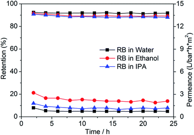
The longer-term stability of PVDF-g-PS20 membranes was evaluated by filtration of RB in different solutions for a period of 24 hours. The results are depicted in Fig. 7. Only a slight decline in retention occurred during the first 10 hours of filtration after which the retention remained stable, indicating excellent stability of prepared membrane.
Conclusions
The PVDF-based SRNF-membrane was reported. Applying only the phase inversion process proved incapable of producing membranes with MWCO with NF-range. The grafting was required to further densify the selective layer and increased the separation capability. The reported fabrication process of creating PVDF-g-PS membrane provides a versatile route to develop good SRNF membranes with optimum performance. The ability to modify the surface of this chemical, thermal and dimensional stable membrane opens up vast opportunities to fine-tune the characteristics of porous membranes, enabling the development of better SRNF membranes. In addition, the research on the permeance of pure solvents provided an opportunity to further enhance the understanding of the physico-chemical SRNF transport mechanism in general and for this new membrane type in particular.Acknowledgements
The authors greatly acknowledge the financial support from China Natural Science Foundation (No. 21606119) and the general project of Liaoning province department of education (No. L201683667).Notes and references
- S. P. Nunes and K.-V. Peinemann, Membrane technology: in the chemical industry, John Wiley & Sons, 2006 Search PubMed.
- V. Nwuha, J. Food Eng., 2000, 44, 233–238 CrossRef.
- J. Whu, B. Baltzis and K. Sirkar, J. Membr. Sci., 1999, 163, 319–331 CrossRef CAS.
- L. P. Rama, M. Cheryan and N. Rajagopalan, Lipid/Fett, 1996, 98, 10–14 CrossRef.
- K. K. Reddy, T. Kawakatsu, J. B. Snape and M. Nakajima, Sep. Sci. Technol., 1996, 31, 1161–1178 CrossRef CAS.
- P. Marchetti, M. F. Jimenez Solomon, G. Szekely and A. G. Livingston, Chem. Rev., 2014, 114, 10735–10806 CrossRef CAS PubMed.
- M. G. Buonomenna and J. Bae, Sep. Purif. Rev., 2014, 44, 157–182 CrossRef.
- G. Szekely, M. F. Jimenez-Solomon, P. Marchetti, J. F. Kim and A. G. Livingston, Green Chem., 2014, 16, 4440–4473 RSC.
- D. Bhanushali, S. Kloos, C. Kurth and D. Bhattacharyya, J. Membr. Sci., 2001, 189, 1–21 CrossRef CAS.
- F. P. Cuperus and K. Ebert, Nanofiltration: Principles and Applications, Elsevier, Oxford, UK, 2005 Search PubMed.
- P. Vandezande, L. E. Gevers and I. F. Vankelecom, Chem. Soc. Rev., 2008, 37, 365–405 RSC.
- W. Koros, Y. Ma and T. Shimidzu, Pure Appl. Chem., 1996, 68, 1479–1489 CrossRef CAS.
- D. Y. Xing, S. Y. Chan and T.-S. Chung, Green Chem., 2014, 16, 1383–1392 RSC.
- I. B. Valtcheva, P. Marchetti and A. G. Livingston, J. Membr. Sci., 2015, 493, 568–579 CrossRef CAS.
- S.-P. Sun, S.-Y. Chan, W. Xing, Y. Wang and T.-S. Chung, ACS Sustainable Chem. Eng., 2015, 3, 3019–3023 CrossRef CAS.
- J. O. De Zarate, L. Pen and J. Mengual, Desalination, 1995, 100, 139–148 CrossRef.
- M. Khayet and T. Matsuura, Ind. Eng. Chem. Res., 2001, 40, 5710–5718 CrossRef CAS.
- A. Bottino, G. Capannelli, O. Monticelli and P. Piaggio, J. Membr. Sci., 2000, 166, 23–29 CrossRef CAS.
- M. Khayet, C. Feng, K. Khulbe and T. Matsuura, Polymer, 2002, 43, 3879–3890 CrossRef CAS.
- A. Bottino, G. Camera-Roda, G. Capannelli and S. Munari, J. Membr. Sci., 1991, 57, 1–20 CrossRef CAS.
- I. Wienk, R. Boom, M. Beerlage, A. Bulte, C. Smolders and H. Strathmann, J. Membr. Sci., 1996, 113, 361–371 CrossRef CAS.
- L. P. Cheng and H. Y. Shaw, J. Polym. Sci., Part B: Polym. Phys., 2000, 38, 747–754 CrossRef CAS.
- T.-H. Young, L.-P. Cheng, D.-J. Lin, L. Fane and W.-Y. Chuang, Polymer, 1999, 40, 5315–5323 CrossRef CAS.
- M. R. Bilad, P. Declerck, A. Piasecka, L. Vanysacker, X. Yan and I. F. Vankelecom, J. Membr. Sci., 2011, 379, 146–153 CrossRef CAS.
- M. R. Bilad, P. Declerck, A. Piasecka, L. Vanysacker, X. Yan and I. F. Vankelecom, Sep. Purif. Technol., 2011, 78, 105–112 CAS.
- V. F. Cardoso, A. C. Lopes, G. Botelho and S. Lanceros-Méndez, Soft Mater., 2015, 13, 243–253 CrossRef CAS.
- V. F. Cardoso, G. Botelho and S. Lanceros-Méndez, Mater. Des., 2015, 88, 390–397 CrossRef CAS.
- P. Martins, A. C. Lopes and S. Lanceros-Mendez, Prog. Polym. Sci., 2014, 39, 683–706 CrossRef CAS.
- M.-X. Hu, Q. Yang and Z.-K. Xu, J. Membr. Sci., 2006, 285, 196–205 CrossRef CAS.
- M. M. Nasef, H. Saidi and K. Z. M. Dahlan, J. Membr. Sci., 2009, 339, 115–119 CrossRef CAS.
- H. Okushita, M. Yoshikawa and T. Shimidzu, J. Membr. Sci., 1995, 105, 51–53 CrossRef CAS.
- S. Takahashi, H. Okonogi, T. Hagiwara and Y. Maekawa, J. Membr. Sci., 2008, 324, 173–180 CrossRef CAS.
- X. Wei, R. Wang, Z. Li and A. G. Fane, J. Membr. Sci., 2006, 273, 47–57 CrossRef CAS.
- X. Wei, Z. Wang, J. Chen, J. Wang and S. Wang, J. Membr. Sci., 2010, 346, 152–162 CrossRef CAS.
- G.-M. Qiu, L.-P. Zhu, B.-K. Zhu, Y.-Y. Xu and G.-L. Qiu, J. Supercrit. Fluids, 2008, 45, 374–383 CrossRef CAS.
- V. Freger, J. Gilron and S. Belfer, J. Membr. Sci., 2002, 209, 283–292 CrossRef CAS.
- Z.-P. Zhao, J. Li, J. Chen and C.-X. Chen, J. Membr. Sci., 2005, 251, 239–245 CrossRef CAS.
- A. I. Schäfer, A. G. Fane and T. D. Waite, Nanofiltration: principles and applications, Elsevier, 2005 Search PubMed.
- L. E. Gevers, G. Meyen, K. De Smet, P. Van De Velde, F. Du Prez, I. F. Vankelecom and P. A. Jacobs, J. Membr. Sci., 2006, 274, 173–182 CrossRef CAS.
- X. Qiu, W. Li, S. Zhang, H. Liang and W. Zhu, J. Electrochem. Soc., 2003, 150, A917–A921 CrossRef CAS.
- M. Mulder, Basic principles of membrane technology, Springer Science & Business Media, 1996 Search PubMed.
- A. F. Ismail and L. P. Yean, J. Appl. Polym. Sci., 2003, 88, 442–451 CrossRef CAS.
- E. Oikawa, K. Katoh and T. Aoki, Sep. Sci. Technol., 1991, 26, 569–584 CrossRef CAS.
- G. Ross, J. Watts, M. Hill and P. Morrissey, Polymer, 2000, 41, 1685–1696 CrossRef CAS.
- M. Bulut, L. E. Gevers, J. S. Paul, I. F. Vankelecom and P. A. Jacobs, J. Comb. Chem., 2006, 8, 168–173 CrossRef CAS PubMed.
- P. Vandezande, L. E. Gevers, J. S. Paul, I. F. Vankelecom and P. A. Jacobs, J. Membr. Sci., 2005, 250, 305–310 CrossRef CAS.
Footnote |
| † Electronic supplementary information (ESI) available. See DOI: 10.1039/c7ra03998k |
| This journal is © The Royal Society of Chemistry 2017 |

