 Open Access Article
Creative Commons Attribution 3.0 Unported Licence
UV-crosslinked poly(arylene ether sulfone) – LAPONITE® nanocomposites for proton exchange membranes†
Sun Hwa Lee‡
a,
Won Jun Lee‡ ab,
Tae Kyoung Kimcd,
Mustafa K. Bayazitb,
Sang Ouk Kim
 a and
Yeong Suk Choi*e
aDepartment of Materials Science and Engineering, KAIST, 291 Daehak-ro, Yuseong-gu, Daejeon 34141, Republic of Korea
bDepartment of Chemistry, Imperial College London, London, SW7 2AZ, UK
cResearch Institute of Chemical and Electronic Materials, Samsung Cheil Industries Inc., Uiwang-si, 437-711, Republic of Korea
dA123 Systems, 200 West St., Waltham, MA 02451, USA
eOrganic Materials Lab, Samsung Advanced Institute of Technology, 130, Samsung-ro, Yeongtong-gu, Suwon-si, Gyeonggi-do 16678, Republic of Korea. E-mail: yeongsuk.choi@samsung.com
First published on 30th May 2017
Abstract
The dimensional stability and barrier properties of proton exchange membranes are critical issues for high-performance proton exchange membrane fuel cells (PEMFCs). In this work, we introduce a viable and effective strategy for preparing high proton-conductive polymer membranes with remarkable dimensional stability and barrier properties. Sulfonated poly(arylene sulfone)s (sPASs) with a UV-crosslinkable monomer, 2,2′-diallylbisphenol A (DABPA), is successfully synthesized via condensation polymerization, showing competitive molecular weights and sulfonation degrees to the neat polymer. Crosslinked nanocomposite membranes can be fabricated by incorporating soft bridge molecules and exfoliated LAPONITE® nanofillers, and subsequent UV-crosslinking. The sPAS–LAPONITE® nanocomposite membranes show greatly improved dimensional stabilities and barrier properties including remarkably reduced swelling ratio in solvent or methanol aqueous solutions. These enhanced properties lead to excellent performance in a direct methanol fuel cell (DMFC) test, surpassing that of a commercially available Nafion membrane based devices.
1. Introduction
The design of proton exchange membranes (PEMs) and their deterministic performance are core opportunities as well as challenges for direct methanol fuel cells (DMFC).1–4 The membrane plays a pivotal role in the DMFC,5,6 isolating electronically the anode from the cathode, preventing the loss of methanol, and enabling transport of protons.7,8 Therefore, the ability to provide enhanced conductivity at a reduced methanol crossover with superior dimensional stabilities has been a major focus in membrane research.9–11 However, perfluorinated polymer PEMs, such as Nafion or Aciplex,12,13 show appropriate conductivity in the range of 0.1 S cm−1 but suffer high methanol crossover and geometry deterioration under moderate operating conditions (up to 90 °C).14–16So far, composite membranes have emerged with the function to reduce methanol crossover significantly by engineering their chemical structures (<6 × 10⁻⁶ cm2 s−1).17,18 In particular, sulfonated poly(arylene sulfone) (sPAS) composite membranes have demonstrated their great potential with improved mechanical strength,19 low methanol permeability,20 and lower cell resistance in the presence of additives,21 such as clay,22,23 CNTs,24 and graphene.25,26 Alternative approaches to adapt the surface properties on sPAS include diazotization reactions,27 grafting sulfonic acid side groups,28 and copolymerization.29,30 Intrinsically, when PAS has a high sulfonation degree which is required for high proton conductivity,31 it gives rise to excessive swelling in aqueous media,32 thereby leading to considerable degradation in mechanical robustness,33 low dimensional stability and high methanol permeability in the long-term.34 In this regard, securing both dimensional stability and barrier properties with high proton conductive PAS membrane is a formidable challenge.20,35–39
Here, we present a straightforward fabrication of sPAS–LAPONITE® composite membranes via direct copolymerization and photo-crosslinking, which have distinguished dimensional stability, low methanol permeability and high proton conductivity. UV-crosslinkable sPAS random copolymers were copolymerized with diallyl bisphenol A monomers.
The functional allyl groups on bisphenol A monomer could generate a high crosslinked dense network that results in considerably enhanced chemical and mechanical stability without deteriorating its high proton conductivity. Furthermore, the introduction of completely exfoliated LAPONITE® could improve the selective proton/methanol transport of sPAS without any hindrance of proton pathways (Fig. 1). The effects of UV-crosslinking sPAS in the presence of LAPONITE®, such as glass transition temperatures, the swelling behavior, the methanol diffusion coefficient, mechanical strength, and the proton conductivity, were thoroughly investigated. Furthermore, the effect of UV-crosslinked sPAS–LAPONITE® nanocomposite membranes on DMFC performances was elucidated.
 | ||
| Fig. 1 Conceptual schematic for the fabrication of the UV-crosslinked sPAS–LAPONITE® nanocomposite membranes. | ||
2. Experimental
2.1 Materials
4,4′-Dichlorodiphenyl sulfone (DCDPS, Tokyo Chemical Inc.), sulfonated 4,4′ dichlorodiphenyl sulfone, sodium salt (Na–sDCDPS),40 and bisphenol A (BPA, Aldrich) were purified by recrystallization before condensation polymerization. 2,2′-Diallylbisphenol A (DABPA, Aldrich),41,42 1,6-hexanediol diacrylate (HDDA, Aldrich), benzophenone (Aldrich), and LAPONITE® (Laporte Absorbents) were used as received. Before polymerization, the purity of DABPA was analyzed using an Agilent 5973N gas chromatography-mass spectrometry (GC-MS) for calculating stoichiometric ratio. The GC-MS data showed that the purchased DABPA consisted of 88% diallyl-BPA, 5% triallyl BPA, and 2% untreated BPA. Based on the GC-MS results, we determine that the contents of diol in DABPA is about 95% and the polymerization recipe was prepared with determined purity of DABPA, 95%.2.2 Synthesis of UV-crosslinkable sPAS
UV-crosslinkable sPASs were synthesized, as described in our previous work.22,23 Briefly, the stoichiometric ratio of dihalides (4,4′-dichlorodiphenyl sulfone (DCDPS) and sulfonated 4,4′-dichlorodiphenyl sulfone, sodium salt (Na–sDCDPS)) to diols (bisphenol A (BPA) and DABPA) was 1![[thin space (1/6-em)]](https://www.rsc.org/images/entities/char_2009.gif) :
:![[thin space (1/6-em)]](https://www.rsc.org/images/entities/char_2009.gif) 1. Amounts of DABPA and Na–sDCDPS in the diols and dihalides were varied as listed in Table 1. The monomers, potassium carbonate (K2CO3, Aldrich), N-methyl-2-pyrrolidinone (NMP), and toluene were added into a two-necked flask, equipped with a dean-stark trap and an N2 inlet. Polymerization was carried out at 180 °C for 6 h. After the completion of polymerization, the reactor was air-cooled to room temperature. The synthesized UV-crosslinkable sPAS was collected by precipitation into 2-propanol and washed with deionized water three times.
1. Amounts of DABPA and Na–sDCDPS in the diols and dihalides were varied as listed in Table 1. The monomers, potassium carbonate (K2CO3, Aldrich), N-methyl-2-pyrrolidinone (NMP), and toluene were added into a two-necked flask, equipped with a dean-stark trap and an N2 inlet. Polymerization was carried out at 180 °C for 6 h. After the completion of polymerization, the reactor was air-cooled to room temperature. The synthesized UV-crosslinkable sPAS was collected by precipitation into 2-propanol and washed with deionized water three times.
| The molar ratio (%) of DCDPS/Na–sDCDPS/BPA/DABPA | Mn | Mw | Sulfonation degree [%] (feed ratio/measured)b | DABPA content [%] (feed ratio/measured)c |
|---|---|---|---|---|
| a Mn: number-average molecular weight, Mw: weight-average molecular weight.b Sulfonation degree is the molar ratio (%) of Na–sDCDPS to total dihalides.c DABPA content is the molar ratio (%) of DABPA to total diols. The feed ratio means the loaded amount of reactants before synthesis. | ||||
| 70/30/100/0 | 809![[thin space (1/6-em)]](https://www.rsc.org/images/entities/char_2009.gif) 000 000 |
1![[thin space (1/6-em)]](https://www.rsc.org/images/entities/char_2009.gif) 273 273![[thin space (1/6-em)]](https://www.rsc.org/images/entities/char_2009.gif) 000 000 |
30/28.0 | 0/0 |
| 70/30/90/10 | 981![[thin space (1/6-em)]](https://www.rsc.org/images/entities/char_2009.gif) 000 000 |
1![[thin space (1/6-em)]](https://www.rsc.org/images/entities/char_2009.gif) 928 928![[thin space (1/6-em)]](https://www.rsc.org/images/entities/char_2009.gif) 000 000 |
30/27.6 | 10/8.5 |
| 70/30/75/25 | 923![[thin space (1/6-em)]](https://www.rsc.org/images/entities/char_2009.gif) 000 000 |
1![[thin space (1/6-em)]](https://www.rsc.org/images/entities/char_2009.gif) 766 766![[thin space (1/6-em)]](https://www.rsc.org/images/entities/char_2009.gif) 000 000 |
30/29.1 | 25/22.1 |
| 70/30/50/50 | 920![[thin space (1/6-em)]](https://www.rsc.org/images/entities/char_2009.gif) 000 000 |
1![[thin space (1/6-em)]](https://www.rsc.org/images/entities/char_2009.gif) 700 700![[thin space (1/6-em)]](https://www.rsc.org/images/entities/char_2009.gif) 000 000 |
30/29.4 | 50/43.2 |
| 70/30/25/75 | N/A (gel) | N/A (gel) | 30/30.5 | 75/69.6 |
| 70/30/0/100 | N/A (gel) | N/A (gel) | 30/33.3 | 100/81.2 |
| 80/20/75/25 | 1![[thin space (1/6-em)]](https://www.rsc.org/images/entities/char_2009.gif) 202 202![[thin space (1/6-em)]](https://www.rsc.org/images/entities/char_2009.gif) 000 000 |
2![[thin space (1/6-em)]](https://www.rsc.org/images/entities/char_2009.gif) 394 394![[thin space (1/6-em)]](https://www.rsc.org/images/entities/char_2009.gif) 000 000 |
20/20.0 | 25/20.0 |
2.3 Dispersion of LAPONITE® on UV-crosslinkable sPAS
Pre-determined amounts of LAPONITE® was dispersed in 10 mL of NMP by ultrasonication for 1 h. After the temperature of the reactor for crosslinkable sPAS polymerization was lowered to 70 °C, LAPONITE® dispersed in NMP was transferred into the reactor and stirred for 12 h. The prepared sPAS–LAPONITE® nanocomposites were recovered by precipitation into 2-propanol and dissolved and washed with deionized water three times. It should be noted that LAPONITE® is not dissolved in both 2-propanol and deionized water.2.4 Fabrication of UV-crosslinked membrane
UV-crosslinkable sPAS samples with or without LAPONITE® were stirred and dissolved in NMP for more than 24 h. 1,6-Hexanediol diacrylate (HDDA) and benzophenone were added to the solution and stirred until they became transparent.43 The molar ratio of the acrylate groups of HDDA to the allyl groups of sPAS was varied from 0% to 15%. 3 wt% of benzophenone was used as a photoinitiator for UV-crosslinking.44 The UV-crosslinkable sPAS films were prepared via doctor blade technique from functional sPAS solutions. The blade gap and concentration of polymer dope were 500 μm and 10 wt%, respectively which results in an average film thickness of ∼50 μm. Followingly, obtained films were crosslinked using a 365 nm mercury lamp (ORIEL) for 25 min. After crosslinking, the films were dried under vacuum at 150 °C for 24 h to remove any residual solvent. Before DMFC performance tests, UV-cured membranes were boiled in a 1 M H2SO4 aqueous solution at 95 °C for 2 h to transform the Na salt-form membranes into protonic-form (acid-form) membranes and then washed with deionized water until excess sulfuric acid had been completely removed.452.5 Characterization
Nuclear magnetic resonance (NMR) experiments were performed on a Bruker Advance DPX 300 spectrometer equipped with a Bruker multinuclear z-gradient with a magnetic strength of 53.5 G cm−1 in the z direction. The samples (1.5 g) were dissolved in deuterated dimethyl sulfoxide (1 mL) for 1H-NMR characterization. Molecular weights and polydispersity index (PDI) were measured using a Polymer Lab apparatus PLGPC210, equipped with two Tosoh Biosep G2500 PWXL PL gel mixed B columns and a Viscotek TDA302 refractive index detector at 40 °C. Thermogravimetric analyses (TGA) were performed using a Perkin-Elmer TGA-7 instrument from room temperature to 700 °C with a ramping rate of 10 °C per min under a nitrogen atmosphere. For characterization of the dispersed morphology of LAPONITE®, membranes were molded with epoxy resin, sliced to yield a roughly 90 nm thick film using a RMC microtome Powertome XL, and placed on copper grids. Transmission electron microscopy (TEM) images were obtained using a Philips CM-20 scanning transmission electron microscope with an accelerating voltage of 200 kV. Mechanical properties of the membranes were measured using nano-indentation, XP of MTS. X-ray diffraction (XRD) patterns were obtained by using a Philips X'pert Pro X-ray diffractometer, equipped with a Cu Kα source (λ = 0.15406 nm) at 30 kV and 30 mA. The diffractograms were scanned with a scanning rate of 2° min−1 in a 2θ range of 1.2–10° at room temperature. Swelling behavior measurements of membranes in MeOH aqueous solution were carried out as follows. The membranes were dried under high vacuum at 110 °C for 12 h. After being dried, the length, width and thickness of the membranes were measured and then immersed in a MeOH aqueous solution of MeOH (1 mol, 32 g) and water (1 mol, 18 g) for 24 h at room temperature. The sizes (length, width, and thickness) of the swollen membranes were re measured after removing the MeOH aqueous solution from membrane surfaces. Swelling ratio of each membrane (%) was calculated using the size variation of the membrane in wet and dried states. Ion conductivity was evaluated by a four-point probe method using a Solartron 1260 a.c. impedance analyzer with an amplitude of 20 mV and a frequency range of 1 Hz to 500 kHz. Each membrane (1.5 × 4.0 cm2) was fitted in a Teflon conductivity test cell that consisted of two Pt wires (a counter electrode and a working electrode) and two Pt foils (reference electrode 1 and reference electrode 2). The Teflon test cell was immersed in a de-ionized water bath to maintain the membrane at constant humidity and temperature. Membrane resistance was calculated using the intercept value of the real axis (Z′) in the complex plane that is composed of the real axis and the imaginary axis (Z′′). Unit conductance (k) was initially calculated via the following eqn (1):
 | (1) |
Since unit conductance (k) is extrinsically dependent on thickness, their intrinsic ionic conductivity (σ) was calculated via the following eqn (2):
| σ = k × L | (2) |
MeOH permeability measurements were performed with a refractive index detector (RI750F, Young In Co., Korea). In detailed configuration, MeOH permeability measurements of the membranes were performed using a diffusion cell consisting of two reservoirs at room temperature. Membranes with a transporting area of 4 cm2 were placed between a MeOH reservoir and a water reservoir. The internal volume of each reservoir was 35 mL. MeOH permeability was calculated using the following eqn (3), which describes the relationship between the MeOH concentration and elapsed time:
 | (3) |
2.6 Fabrication of membrane-electrode-assembly (MEA) and cell performance test
For the fabrication of a MEA, cathode catalyst ink was prepared by dispersing a commercial Pt black catalyst (HiSpec 1000 from Johnson Matthey Fuel Cells) in alcohol solution with Nafion dispersion. The catalyst ink was coated onto a gas diffusion layer to form a cathode catalyst layer of 4.5 mg cm−2 Pt. (HiSpec 6000 from Johnson Matthey Fuel Cells, Pt/Ru ratio = 1/1). Both electrodes and membranes were hot-pressed to fabricate a MEA with a reaction area of 10 cm2. Active DMFC single cell tests were conducted at 60 °C with 1 M MeOH aqueous solution and air as fuel for the anode and the cathode, respectively. The MeOH solution was fed into the anode by means of a microflow pump in an amount of a 2.5 stoichiometry. The performance of a single cell with a UV-crosslinked sPAS membrane was compared with that of a reference single cell with Nafion 115.3. Results and discussion
3.1 Synthesis and chemical analysis of UV-crosslinked sPAS
As shown in Fig. 2, UV-crosslinkable sPAS random copolymers were synthesized from a mixture of two kinds of diol monomers (BPA and DABPA) and two kinds of dihalide monomers (DCDPS and Na–sDCDPS) by a condensation polymerization. The degree of crosslinking and the degree of sulfonation were controlled by adjusting the feed ratios of the UV-crosslinkable DABPA diol monomer (with allyl groups) and the sulfonated dihalide monomer of Na–sDCDPS, respectively, in the same stoichiometric ratio of diols and dihalides. After polymerization, LAPONITE® nanofillers were homogeneously dispersed in the UV-crosslinkable sPAS matrix via simple solution intercalation without any dispersants or organic modifiers. Solid state [2 + 2] photo-cycloadditions yielding a cyclobutane ring are known to be very useful for crosslinking in the field of polymer chemistry.46,47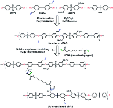 | ||
| Fig. 2 Condensation random copolymerization for the synthesis of UV-crosslinkable sPAS and photo-crosslinking. | ||
In this regard, the photo-crosslinking of functional sPASs were achieved by the [2 + 2] cycloaddition of crosslinking agent (HDDA) with allyl moieties bound to the sPAS backbone, which produced UV-crosslinked sPAS–LAPONITE® nanocomposite membranes. The chemical structure of as-prepared sPAS was confirmed with 1H NMR spectrum (see Fig. 3). The NMR spectrum exhibits typical proton peaks, assigned as follows: a peak at 8.26δ for the proton neighboring sulfonic group of Na–sDCDPS (c′); a peak at 7.88δ for the proton of DCDPS (a); a shoulder peak at 7.58δ for the proton positioned at the opposite side of the sulfonic moiety of Na–sDCDPS (a′); a peak at 7.52δ for the protons of DCDPS (b); a peak at 7.27δ for the protons of Na–sDCDPS (b′); a peak at 7.02δ for 1, 1′ (BPA and DABPA); 2, 2′ peaks at 6.67δ for the protons of BPA and DABPA; 6.32δ for the allyl protons of DABPA (4, 5); a peak at 5.62δ for the ethylene proton of DABPA (6); a peak at 1.64δ for the methyl of the BPA (3). The NMR spectrum reveals that the vinyl bond in the allyl group was shifted to the next methylene bond to create a methyl group at the end of the allyl group after condensation polymerization. The contents of sulfonated (Na–sDCDPS) units and crosslinkable (DABPA) units incorporated into the polymer backbone were measured by integrating characteristic NMR peak areas. For the calculation of sulfonation degree, the areal ratio of the peak at 8.26δ (Na–sDCDPS) to the peak at 7.88δ (DCDPS) normalized with the number of corresponding hydrogen atoms for each dihalide were compared. The DABPA contents were estimated from the areal ratio of the peak at 7.02δ (BPA) to that at 6.32δ (DABPA). The content of DABPA units incorporated in the sPAS backbone was substantially less than that of its feed composition. The steric hindrance of allyl side groups in DABPA is supposed to hinder the incorporation of DABPA into the polymer backbone (see Table 1). Nonetheless, all the synthesized sPAS showed high molecular weights, ranging from 800![[thin space (1/6-em)]](https://www.rsc.org/images/entities/char_2009.gif) 000 g mol−1 to 1
000 g mol−1 to 1![[thin space (1/6-em)]](https://www.rsc.org/images/entities/char_2009.gif) 240
240![[thin space (1/6-em)]](https://www.rsc.org/images/entities/char_2009.gif) 000 g mol−1, demonstrating that the incorporation of both DABPA and Na–sDCDPS monomers did not significantly influence the overall polymerization rate (ESI, Fig. S1†). It should be noted that the allyl group in the DABPA unit was not thermally crosslinked during polymerization when it was less than 50%.
000 g mol−1, demonstrating that the incorporation of both DABPA and Na–sDCDPS monomers did not significantly influence the overall polymerization rate (ESI, Fig. S1†). It should be noted that the allyl group in the DABPA unit was not thermally crosslinked during polymerization when it was less than 50%.
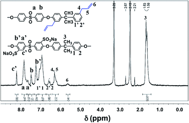 | ||
| Fig. 3 1H NMR spectrum of sPAS synthesized with 30% of Na–sDCDPS in dihalides and 25% of DABPA in diols. | ||
However, when its content was more than 50%, reaction media underwent gelation.
3.2 Glass transition temperature and dimensional stability
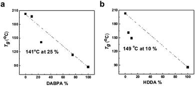
Fig. 4 presents the variation of the glass transition temperature (Tg) of sPASs with the contents of crosslinkable DABPA unit and soft bridge HDDA additive. As shown in Fig. 4(a), the Tg of uncrosslinked sPAS decreased from 203 °C (0% of DABPA) to 86.6 °C (100% of DABPA) with DABPA content. The decrease of Tg was attributed to the flexible allyl moiety in the DABPA unit. Fig. 4(b) shows the effect of a soft segment HDDA on the Tg of UV-crosslinked sPASs. Since polymerized HDDA has a low Tg of ∼62 °C, the Tg of UV-cured sPASs with HDDA decreased with HDDA content from 203 °C to 85 °C. These results signify that the Tg of our sPAS polymers can be tuned by the crosslinking density, which is governed by the feed ratio of DABPA and the amount of soft segment determined by the amount of HDDA, without sacrificing molecular weight. The dimensional stability of the UV-crosslinked sPAS membrane was tested by immersing it into NMP, a good solvent of uncrosslinked sPAS.Two 5 × 5 mm2 size crosslinked membranes were prepared and one was immersed in NMP for 48 h (Fig. 5). Fig. 5(b) shows that, unlike un-crosslinked polymers, which are highly swollen in NMP, the crosslinked membrane maintained its structural integrity. The dimensional stability of our UV-crosslinked sPAS was also tested in a harsh environment of a 3 M MeOH aqueous solution for 48 h. The crosslinking greatly improved the dimensional stability (as revealed by a low degree of swelling) of the membrane (see Table S1†). The result indicates that the crosslinked polymers have better dimensional stability than uncrosslinked linear polymers.
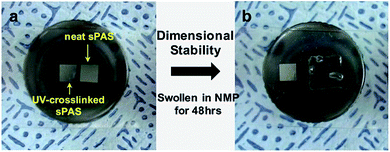 | ||
| Fig. 5 Dimensional stability test of UV-crosslinked sPAS. (a) Two 5 × 5 mm2 size UV-crosslinked membranes were prepared. (b) The right-side membrane was swollen in NMP for 48 h. | ||
3.3 Effect of the UV-crosslinking and the incorporation of LAPONITE®
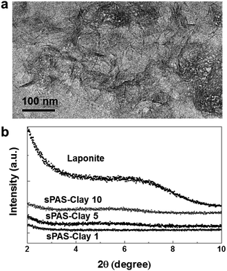
To further improve the dimensional stability and barrier properties of the UV-crosslinkable sPAS membrane, nanosized LAPONITE® fillers were dispersed before crosslinking. The TEM image of a highly loaded (10 wt%) nanocomposite reveals a homogeneously exfoliated morphology of LAPONITE® fillers in the sPAS matrix (Fig. 6(a)). The fully exfoliated and homogeneously dispersed morphology was well-preserved during UV-crosslinking.The homogeneous dispersion of LAPONITE® in membrane can be attributed to their excellent compatibility with sPAS, which is directly related to polarity of sPAS. It is worthwhile to note that an increase concentration of sulfonic acid improves the compatibility between hygroscopic LAPONITE® and PAS matrix.48 As shown in Fig. 6(b), XRD measurements verified that the LAPONITE® nanocomposites showed the exfoliated morphology up to ∼10 wt% LAPONITE® content, beyond which they showed intercalated morphology. The addition of a small amount of LAPONITE® nanofillers has shown significant effects for the mechanical properties (Fig. 7). The elastic modulus and hardness for UV-crosslinked sPAS membrane were 6.2 GPa and 300 MPa, respectively. In the presence of 1 wt% of LAPONITE®, the elastic modulus and hardness were increased by 15% (7.1 GPa) and 5% (315 MPa), respectively. It reveals that the UV-crosslinking and introduction of LAPONITE® offers better dimensional stability and stiffness over Nafion 115, as reflected in mechanical properties. As mentioned above, the dimensional stability of a PEM is closely related to its MeOH permeability and proton conductance.18,49 These properties of UV-crosslinked PEMs without LAPONITE® nanofillers are summarized in Table 2. Without LAPONITE® filler, the major parameter affecting the permeability and proton conductance of PEM was the degree of sulfonation. As the degree of sulfonation increased, the MeOH permeability was deteriorated, while proton conductance was improved.
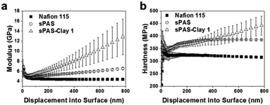 | ||
| Fig. 7 (a) Young's modulus and (b) hardness of Nafion 115, UV-crosslinked sPAS, and UV-crosslinked sPAS–LAPONITE® composite membranes. The maximum indentation depth was set to be 1 μm. | ||
| Samplea | Weight fraction of LAPONITE®b [%] | Ion conductivity [S cm−1] | Permeability [×10−7 cm2 s−1] | Selectivity [×105 S s cm−3] | Ion conductance [S cm−2] |
|---|---|---|---|---|---|
| a Na–sDCDPS/DABPA/HDDA mean the molar ratio (%) of specific reactants to total dihalides/diols/diallyl groups of loaded reactants.b Selectivity = ion conductivity/MeOH permeability. | |||||
| sPAS | 0 | 0.038 | 4.85 | 0.78 | 8.4 |
| sPAS–LAPONITE® 1 | 1 | 0.037 | 2.90 | 1.27 | 8.2 |
| sPAS–LAPONITE® 5 | 5 | 0.036 | 2.77 | 1.30 | 8 |
| sPAS–LAPONITE® 10 | 10 | 0.035 | 2.73 | 1.29 | 7.8 |
| Nafion 115 | — | 0.094 | 13.8 | 0.68 | 6.7 |
To better understand the combined effect of ion conductivity, thickness, and methanol permeability, we have calculated the membrane selectivity, as the proton conductivity divided by the MeOH permeability. From the selectivity, it shows clearly that a low degree of sulfonation improves the selectivity. Nevertheless, it should be noted that a low degree of sulfonation definitely lowers the entire unit conductance, as it has lower ionic exchange capacity (IECs). Interestingly, the content of soft linker HDDA did not influence the MeOH permeability or proton conductance of the crosslinked membranes. This demonstrates that the incorporation of HDDA with UV-crosslinking improved the dimensional stability of the sPAS membrane without sacrificing proton conductance.
Table 3 shows the permeability and proton conductance of sPAS–LAPONITE® nanocomposites as a function of LAPONITE® fillers. It should be noted that all sPAS composite membranes have been fabricated with sPAS having 30% of Na–sDCDPS in dihalides, 25% of DABPA in diols, and 10% HDDA. The data shown in Table 3 also confirms that UV-crosslinking did not degrade the proton conductance of the membranes, while the incorporation of LAPONITE® nanofillers greatly improved their barrier properties. Remarkably, the LAPONITE® nanocomposite membranes exhibited permeability values of 2.7–2.9 × 10⁻⁷ cm2 s−1, which are significantly reduced from the value of a neat sPAS membrane without LAPONITE® filler. Despite the dramatic reduction of MeOH permeability, the proton conductivity maintained almost the same value even at a high content of LAPONITE® fillers of up to 10 wt%. Consequently, homogeneously exfoliated LAPONITE® encouraged the remarkable selectivity (1.2–1.3 × 10⁵ S s cm−3), compared to the LAPONITE®-free control sample (0.78 × 10⁵ S s cm−3) and Nafion 115 (0.67 × 10⁵ S s cm−3).
| Na–sDCDPS/DABPA/HDDAa | Thickness [wet, μm] | Ion conductivityc [S cm−1] | Permeability [×10−7 cm2 s−1] | Selectivityb [×105 S s cm−3] | Ion conductance [S cm−2] |
|---|---|---|---|---|---|
| a All sPAS composite membranes have constant the specific molar % ratio (30/25/10) of Na–sDCDPS/DABPA/HDDA.b Weight fraction of LAPONITE® is the weight ratio of LAPONITE® to polymer matrix.c All sPAS composite membranes have constant thickness of 45 μm (wet state) and Nafion 115 has thickness of 140 μm (wet state). | |||||
| 30/25/0 | 45 | 0.039 | 4.85 | 0.81 | 8.7 |
| 30/25/5 | 45 | 0.032 | 4.34 | 0.74 | 7.1 |
| 30/25/10 | 45 | 0.038 | 4.85 | 0.78 | 8.4 |
| 25/25/0 | 45 | 0.030 | 2.95 | 1.02 | 6.7 |
| 20/25/0 | 45 | 0.021 | 0.39 | 5.31 | 4.7 |
| 20/25/10 | 45 | 0.025 | 0.40 | 6.30 | 5.6 |
| 20/25/25 | 45 | 0.019 | 0.41 | 4.68 | 4.2 |
| 20/25/50 | 45 | 0.025 | 0.54 | 4.66 | 5.6 |
| Nafion 115 | 140 | 0.094 | 13.8 | 0.68 | 6.7 |
This is mainly due to a significant reduction in MeOH crossover, which is directly related to the presence of impermeable LAPONITE® platelets as well as microstructure change induced by LAPONITE®.50,51 Additionally, the microstructure (Fig. 6(a)) of sPAS–LAPONITE® (1 wt%) composite membranes confirms the alterations of the network structure, which directly influences mass transport of water and methanol.
3.4 DMFC performance
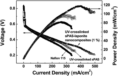
To investigate electrochemical behavior, the performance of UV-crosslinked nanocomposite membranes in a DMFC cell was tested in a single cell with an active area of 10 cm2. Fig. 8 shows the polarization curves of DMFCs obtained from a voltage scan. The single cell incorporated with UV-crosslinked sPAS–LAPONITE® nanocomposite membrane (1 wt%) exhibited better performance than UV-crosslinked sPAS membrane without nanofillers and the Nafion 115-based cell: the maximum power-density value at 60 °C of the former was 117.1 mW cm−2, which is significantly higher than those (96.5 and 82.1 mW cm−2) for UV-crosslinked sPAS membrane and Nafion 115, respectively. The better performance with sPAS–LAPONITE® composite membranes could be attributed to two effects. Considering low MeOH crossover, less methanol permeating through the membranes ultimately lead to an increase in open circuit voltage (0.84 V) with less oxidizing of MeOH in cathode catalytic layers. Additionally, the high ionic conductance of sPAS–LAPONITE® composite membranes could lower ohmic resistance values, which was confirmed in our previous work.234. Conclusion
We have demonstrated UV-crosslinked sPAS–LAPONITE® nanocomposite PEMs showing remarkable performance. UV-crosslinking of the polymer backbone via [2 + 2] cycloaddition and homogeneous exfoliation of LAPONITE® nanofillers enhanced the dimensional stability and MeOH barrier property of the sPAS membrane, while maintaining high proton conductivity. A single cell DMFC, incorporating a crosslinked nanocomposite membrane, exhibited remarkable performance (maximum power-density of 117.1 mW cm−2), which exceeds that of a commercially available Nafion 115-based cell (maximum power-density of 82.1 mW cm−2) under the same operating conditions. Our strategy of crosslinked nanocomposite preparation is potentially useful for the fabrication of robust film, solid-electrolyte, and functional membranes based on various polymers.Acknowledgements
This work was supported by Samsung Advanced Institute of Technology.Notes and references
- B. C. H. Steele and A. Heinzel, Nature, 2001, 414, 345–352 CrossRef CAS PubMed.
- J. R. Varcoe and R. C. T. Slade, Fuel Cells, 2005, 5, 187–200 CrossRef CAS.
- Y. Wang, K. S. Chen, J. Mishler, S. C. Cho and X. C. Adroher, Appl. Energy, 2011, 88, 981–1007 CrossRef CAS.
- H. Zhang and P. K. Shen, Chem. Rev., 2012, 112, 2780–2832 CrossRef CAS PubMed.
- K. D. Kreuer, J. Membr. Sci., 2001, 185, 29–39 CrossRef CAS.
- R. Dillon, S. Srinivasan, A. S. Aricò and V. Antonucci, J. Power Sources, 2004, 127, 112–126 CrossRef CAS.
- T. E. Springer, T. A. Zawodzinski and S. Gottesfeld, J. Electrochem. Soc., 1991, 138, 2334–2342 CrossRef CAS.
- V. Neburchilov, J. Martin, H. Wang and J. Zhang, J. Power Sources, 2007, 169, 221–238 CrossRef CAS.
- M. A. Hickner, A. M. Herring and E. B. Coughlin, J. Polym. Sci., Part B: Polym. Phys., 2013, 51, 1727–1735 CrossRef CAS.
- C. H. Lee, H. B. Park, Y. S. Chung, Y. M. Lee and B. D. Freeman, Macromolecules, 2006, 39, 755–764 CrossRef CAS.
- A. Aricò, D. Sebastian, M. Schuster, B. Bauer, C. D'Urso, F. Lufrano and V. Baglio, Membranes, 2015, 5, 793 CrossRef PubMed.
- K. A. Mauritz and R. B. Moore, Chem. Rev., 2004, 104, 4535–4586 CrossRef CAS PubMed.
- R. Souzy and B. Ameduri, Prog. Polym. Sci., 2005, 30, 644–687 CrossRef CAS.
- A. Heinzel and V. M. Barragán, J. Power Sources, 1999, 84, 70–74 CrossRef CAS.
- S. J. Peighambardoust, S. Rowshanzamir and M. Amjadi, Int. J. Hydrogen Energy, 2010, 35, 9349–9384 CrossRef CAS.
- F. Lufrano, V. Baglio, P. Staiti, V. Antonucci and A. S. Arico, J. Power Sources, 2013, 243, 519–534 CrossRef CAS.
- A. Kraytsberg and Y. Ein-Eli, Energy Fuels, 2014, 28, 7303–7330 CrossRef CAS.
- E. Bakangura, L. Wu, L. Ge, Z. Yang and T. Xu, Prog. Polym. Sci., 2016, 57, 103–152 CrossRef CAS.
- K. H. Lee, D. H. Cho, Y. M. Kim, S. J. Moon, J. G. Seong, D. W. Shin, J.-Y. Sohn, J. F. Kim and Y. M. Lee, Energy Environ. Sci., 2017, 10, 275–285 CAS.
- P. Wen, Z. Zhong, L. Li, F. Shen, X.-D. Li and M.-H. Lee, J. Membr. Sci., 2014, 463, 58–64 CrossRef CAS.
- B. Bae, T. Hoshi, K. Miyatake and M. Watanabe, Macromolecules, 2011, 44, 3884–3892 CrossRef CAS.
- T. K. Kim, M. Kang, Y. S. Choi, H. K. Kim, W. Lee, H. Chang and D. Seung, J. Power Sources, 2007, 165, 1–8 CrossRef CAS.
- Y. S. Choi, T. K. Kim, E. A. Kim, S. H. Joo, C. Pak, Y. H. Lee, H. Chang and D. Seung, Adv. Mater., 2008, 20, 2341–2344 CrossRef CAS.
- S. H. Joo, C. Pak, E. A. Kim, Y. H. Lee, H. Chang, D. Seung, Y. S. Choi, J.-B. Park and T. K. Kim, J. Power Sources, 2008, 180, 63–70 CrossRef CAS.
- T. Ko, K. Kim, B.-K. Jung, S.-H. Cha, S.-K. Kim and J.-C. Lee, Macromolecules, 2015, 48, 1104–1114 CrossRef CAS.
- B. G. Choi, J. Hong, Y. C. Park, D. H. Jung, W. H. Hong, P. T. Hammond and H. Park, ACS Nano, 2011, 5, 5167–5174 CrossRef CAS PubMed.
- D. Paradesi, D. Samanta, A. B. Mandal and S. N. Jaisankar, RSC Adv., 2014, 4, 26193–26200 RSC.
- J. Pang, S. Feng, H. Zhang, Z. Jiang and G. Wang, RSC Adv., 2015, 5, 38298–38307 RSC.
- J. Xu, Z. Wang, H. Zhang, H. Ni, X. Luo and B. Liu, RSC Adv., 2016, 6, 27725–27737 RSC.
- C. H. Lee, K.-S. Lee, O. Lane, J. E. McGrath, Y. Chen, S. Wi, S. Y. Lee and Y. M. Lee, RSC Adv., 2012, 2, 1025–1032 RSC.
- Y. S. Kim, M. A. Hickner, L. Dong, B. S. Pivovar and J. E. McGrath, J. Membr. Sci., 2004, 243, 317–326 CrossRef CAS.
- L. Fu, G. Xiao and D. Yan, ACS Appl. Mater. Interfaces, 2010, 2, 1601–1607 CAS.
- S. Takamuku and P. Jannasch, Polym. Chem., 2012, 3, 1202–1214 RSC.
- D. W. Shin, S. Y. Lee, N. R. Kang, K. H. Lee, M. D. Guiver and Y. M. Lee, Macromolecules, 2013, 46, 3452–3460 CrossRef CAS.
- Y. H. Kwon, S. C. Kim and S.-Y. Lee, Macromolecules, 2009, 42, 5244–5250 CrossRef CAS.
- P. Wen, Z. Zhong, L. Li, A. Zhang, X.-D. Li and M.-H. Lee, J. Mater. Chem., 2012, 22, 22242–22249 RSC.
- A. H. N. Rao, S. Nam and T.-H. Kim, Int. J. Hydrogen Energy, 2014, 39, 5919–5930 CrossRef CAS.
- Y. Z. Zhuo, A. Nan Lai, Q. G. Zhang, A. M. Zhu, M. L. Ye and Q. L. Liu, J. Membr. Sci., 2015, 491, 138–148 CrossRef CAS.
- M. M. Hasani-Sadrabadi, E. Dashtimoghadam, S. R. Ghaffarian, M. H. Hasani Sadrabadi, M. Heidari and H. Moaddel, Renewable Energy, 2010, 35, 226–231 CrossRef CAS.
- M. Ueda, H. Toyota, T. Ouchi, J.-I. Sugiyama, K. Yonetake, T. Masuko and T. Teramoto, J. Polym. Sci., Part A: Polym. Chem., 1993, 31, 853–858 CrossRef CAS.
- H. Zhang, H. Zhang, X. Li, Z. Mai, W. Wei and Y. Li, J. Power Sources, 2012, 217, 309–315 CrossRef CAS.
- C. Esposito Corcione, R. Striani and M. Frigione, Prog. Org. Coat., 2014, 77, 803–812 CrossRef CAS.
- K. Ma and Z. An, Macromol. Rapid Commun., 2016, 37, 1593–1597 CrossRef CAS PubMed.
- K.-S. Lee, M.-H. Jeong, J.-P. Lee and J.-S. Lee, Macromolecules, 2009, 42, 584–590 CrossRef CAS.
- C. H. Park, S. Y. Lee, D. S. Hwang, D. W. Shin, D. H. Cho, K. H. Lee, T.-W. Kim, T.-W. Kim, M. Lee, D.-S. Kim, C. M. Doherty, A. W. Thornton, A. J. Hill, M. D. Guiver and Y. M. Lee, Nature, 2016, 532, 480–483 CrossRef PubMed.
- T. Junkers, Eur. Polym. J., 2015, 62, 273–280 CrossRef CAS.
- V. Ramamurthy and K. Venkatesan, Chem. Rev., 1987, 87, 433–481 CrossRef CAS.
- H. Zhang and P. K. Shen, Chem. Soc. Rev., 2012, 41, 2382–2394 RSC.
- D.-J. Kim, H.-Y. Hwang, S.-b. Jung and S.-Y. Nam, J. Ind. Eng. Chem., 2012, 18, 556–562 CrossRef CAS.
- I. Nicotera, K. Angjeli, L. Coppola, A. S. Aricò and V. Baglio, Membranes, 2012, 2, 325 CrossRef CAS PubMed.
- Y. Lee, T. K. Kim and Y. S. Choi, Fuel Cells, 2013, 13, 173–180 CrossRef CAS.
Footnotes |
| † Electronic supplementary information (ESI) available. See DOI: 10.1039/c7ra04419d |
| ‡ These authors contributed equally to this work. |
| This journal is © The Royal Society of Chemistry 2017 |

