
 Open Access Article
 This Open Access Article is licensed under a
 Creative Commons Attribution 3.0 Unported Licence
One-pot synthesis and first-principles elasticity analysis of polymorphic MnO2 nanorods for tribological assessment as friction modifiers
Niraj Kumar ab,
Shubrajit Bhaumikc,
Arijit Sen*ab,
A. Pooja Shuklaab and
S. D. Pathakc
ab,
Shubrajit Bhaumikc,
Arijit Sen*ab,
A. Pooja Shuklaab and
S. D. Pathakc
aSRM Research Institute, SRM University, Kattankulathur-603203, India. E-mail: arijit.s@res.srmuniv.ac.in
bDepartment of Physics and Nanotechnology, SRM University, Kattankulathur-603203, India
cDepartment of Mechanical Engineering, SRM University, Kattankulathur-603203, India
First published on 7th July 2017
Abstract
One-pot synthesis of single-crystalline α and β-MnO2 nanorods was carried out by selectively varying the acidic concentrations. Ultrafine one dimensional nanorods with diameters of about 10–40 nm are achieved. The respective phases of the nanorods were then altered through simple optimization in the molar concentration of H2SO4. Morphological transition from microstructure to nanostructure is also examined by changing the acid concentration from high to low. Elastic and tribological properties of these nanomaterials were subsequently explored, with a view to their possible applications as nanoadditives in green lubricants. While β-MnO2 nanorods showed a reduction in the coefficient of friction by about 15%, α-MnO2 nanorods turned out to be even better nanoadditives yielding a reduction of as high as 30%. Moreover, both the polymorphs of MnO2 nanostructures led to lower roughness when used as nanoadditives in the base oil. Our analysis suggests that such enhancement of antiwear properties originates primarily from the mutual interplay between the rolling action and the protective layer formation by respective polymorphs of quasi-1D MnO2. From the first-principles analysis, we envisage that α-MnO2 nanorods may potentially serve as efficient nanoadditives in comparison with β-MnO2 nanorods due to superior elastic properties of the former.
1 Introduction
MnO2 nanostructures are one of the most stable manganese oxides in nature.1 The morphology of MnO2 is often an influential factor due to the presence of highly active sites which offers promising electrokinetics and catalytic activities.2 In particular, the rich polymorphism and structural flexibility with excellent physical and chemical properties of these compounds3,4 have opened the door for a wide range of applications in energy storage systems,5–13 fuel cell catalysis,14–17 water treatment,18,19 biosensing20,21 etc. The past few decades have seen numerous techniques for the synthesis and characterization of these nanomaterials including sol–gel templating,22 thermal decomposition,23 refluxing,24 solvent-free solid reaction,25 electrodeposition26 and hydrothermal methods.27–31 Among these, the hydrothermal method can well be a preferred choice because of its effectiveness, simplicity and low cost. Ramachandran et al.32 have used the hydrothermal method to grow α-phase manganese dioxide nanorods over nitrogen doped graphite nanowires. We have recently developed33,34 MnO2 nanorods and nanowires using a facile hydrothermal treatment without resorting to any seed, capping agent or template.As mentioned earlier, the properties like rich polymorphism and structural flexibility exhibited by MnO2 nanostructures can make it to withstand extreme pressure with high level of anti wear properties, which is a prerequisite for a good lubricant. This brings the need to explore the tribological properties of MnO2 nanostructure as friction modifiers. Although MnO2 nanorods have long been seen as an important electrode material for energy storage, its role as an efficient additive in lubrication has not been studied much. Lubrication is known to be one of the most important mechanical processes in controlling the wear of various machineries.
Commercially petroleum oils are used extensively as lubricants but have major drawback as they are conventionally non-renewable energy sources. This has prompted researches to explore green or renewable energy alternatives.35 Owing to this, biodegradable palm or vegetable oil as lubricants have gained much attention due to their better lubricating properties such as high-index viscosity, low volatility and good lubricity and of course for being perfect green or renewable energy alternatives.36–38 However, their anti-wear properties under extreme pressure as against commercial petroleum oils are not so impressive.39 Zulkifli et al. demonstrated that palm oils suffer from poor anti-wear properties than commercial lubricants.40 Recent progress in synthesis of nanomaterials provides the researchers a new prospect to overcome the above problem with the origin of nanotribology. Additives at nanoscale regime are supposed to improve the anti-wear properties of base oil on mixing due to their high surface activities as compared to their bulk counterpart.41–44 Gulzar et al. have reported an enhancement in the anti-wear property of palm oil by adding CuO and MoS2 nanoparticles as additives.35 Various mechanism for nanoparticles based lubricants, which are responsible for protecting the metal to metal surfaces, include ball bearing effect,45–47 protective film effect,48–52 mending and polishing effect53 etc. In the works of Zhang et al.,54 the friction and wear properties of the base oil get enhanced with the use of WS2 nanorods as additives. For Yang et al.,55 high friction and wear properties of base oil are found to occur with the addition of WSe2 nanorods. They explain the effect of nanorods as additives in terms of the molecule-bearing mechanism of rolling friction and sliding friction of the nanorods between the rubbing surfaces. Besides, Panda et al.56 report the tribological properties of ultra nanocrystalline diamond (UNCD) and diamond nanorod (DNR) films in ambient and nitrogen atmosphere for the implementation of reliable micro- and nano-electromechanical systems (MEMS/NEMS). Also, Liu et al.57 come across the enhanced tribological behaviour of Fe2O3 nanorods based composites with graphene nanosheets and bismaleimides. We have of late reported58 the possibility of enhancing the tribological properties of castor oil with proper additives. Several recent studies have as well demonstrated that the tribological properties of lubricants can be augmented with the selective use of additives.59–63
Our present work focuses on the use of MnO2 nanorods as additives in base oil (palm oil) for evaluating its tribological properties. Unlike other reported works,28–32 we developed a common procedure requiring the common time, temperature and precursors to check rich polymorphism by creating two different polymorphs, α and β of MnO2 and structure flexibility by drawing 1D nanostructures from bulk to micro and finally to nanoscale with simple optimizations in acidic concentration at the start of hydrothermal reaction without using any external agent. The as prepared nanorods were characterized using FESEM, EDX, XRD, FTIR and TEM while the tribological properties were tested for the nanorods as additives in the base oil using the four-ball-test-rig method64,65 followed by the three dimensional profilometers and FESEM. In addition, first principles studies were carried out to analyze the elastic properties of α and β-MnO2 nanorods. To the best of our knowledge, this work reports for the first time on the tribological aspects of α and β-MnO2 nanorods as potential lubrication additives through a comparative analysis.
2 Experimental
2.1 Materials
Being of analytical grade with high purity, all the reagents, viz. Potassium permanganate (KMnO4), sodium nitrite (NaNO2) and sulphuric acid (H2SO4), as purchased from Sigma Aldrich, along with biodegradable palm oil, as collected from a local store, were used without any further treatment. All the solutions were made with de-ionized water.2.2 Synthesis
In a typical synthesis, 2 mM KMnO4 and 3 mM NaNO2 were mixed in 34 ml of de-ionized water using magnetic stirring. Then, 0.4 M H2SO4 was prepared in 6 ml of de-ionized water and was mixed with the above solution by its dropwise addition at frequent intervals under effective stirring. The hydrothermal process was carried out at 160 °C for 12 h after keeping the above prepared solution in autoclave of 80% capacity. After 12 h of hydrothermal reaction the autoclave was left to be cooled in normal ambient condition. The supernatant was discarded and solid residue was collected upon thoroughly washing with de-ionized water. At last, the synthesized product was given heat treatment at 350 °C for 4 h and termed as sample S1. Sample S2 was prepared following the same synthesis procedures but only changing the molar concentration of H2SO4 to 0.3 M.2.3 Preparation of lubricants
Palm oil is chosen as the base oil for its excellent biodegradable and oxidative properties and also its ease of availability. For the preparation of α-MnO2 added palm oil as lubricant, 1 g of the as-prepared α-MnO2 nanorods were mixed with 100 ml of palm oil. The prepared solution was probe sonicated for 60 min to agitate the oil and form a homogenous mixture. The solution was further magnetically stirred thoroughly for nearly 60 min. The concentration of the MnO2 nanorods was 1% by weight (wt). The same procedures were repeated with the β-MnO2 nanorods to prepare β-MnO2 nanorods added palm oil as lubricant.2.4 Characterization
X-ray diffraction (XRD) patterns were extracted from PAN analytical X' Pert Pro diffractometer at 30 mA, 40 kV and 1.54 Å Cu-Kα rays of wavelength. Morphological studies were carried out via ‘Quanta 200 FEG FE-SEM’ and ‘HR-TEM, JEM-2010’. Elemental and functional group analysis was done through ‘Bruker 129 eV’ with ‘Espirit software’ and Perkin Elmer Spectrophotometer respectively. The surfaces of the wear scars on the balls after tribo tests were characterized by the FESEM, a non-contact type of profilometer and an optical microscope.2.5 Tribological setup
A four ball test rig was used to determine the anti-wear property of the nanorods based palm oil. The test balls, as used during the experiment, were of AISI 52100 steel with 12.7 mm diameter and approximately 58–60 Rc. Three balls were placed stationary in the lubricant chamber while the fourth ball was fixed in the rotating ball chuck. About 1 g of MnO2 nanorods (each of α and β type) were added to 100 ml of palm oil. The suspensions were sonicated using a probe sonicator for 60 minutes followed by stirring using a magnetic stirrer for about 45 minutes. The nanorods suspended oil samples were then poured in the lubricant chamber. Approximately, 30 ml of oil samples were used during each experiment. Enough care was taken to ensure full submersion of all the contact points of the balls. The tests were conducted at 392 N (40 kgf), 1200 rpm and 75 °C for 3600 seconds (ASTM D 4172). The data were recorded continuously using a data acquisition system.2.6 Computational details
All the structural relaxations pertaining to α-MnO2 and β-MnO2 quasi-1D nanostructures were performed using the density functional theory (DFT) until the residual forces became smaller than 0.005 eV Å−1. The Hamiltonian in the present work was expanded in real space by way of double-ζ with polarization (DZP) localized pseudoatomic orbitals.66,67 The exchange–correlation energy was described by the spin-polarized generalized gradient approximation (SGGA). We set the grid mesh cut-off to 300 hartree, the force tolerance to 0.01 eV Å−1, and the k-point sampling to 1 × 1 × 300. For the calculation of the elastic constants, the Lagrangian strain and stress tensor were employed so that the stress could be evaluated numerically as a function of small deformations in the simulation cell. The universal linearly independent coupling strain (ULICS) vectors,68 as adopted here, ensured that all the stress components and elastic constants were coupled.3 Results and discussions
MnO2 nanorods were prepared from the redox reaction between permanganate and nitrite ions in the presence of sulphuric acid. In brief, the reaction mechanism can be described as:21| 2MnO4− + 3NO2− + 2H+ → 2MnO2 + 3NO3− + H2O | (A) |
According to the Le Chatelier's principle, the feasibility of the reaction depends on the involvement of protons. The protons needed for the reaction is supplied by the sulphuric acid. Here, permanganate ion acts as oxidants and resource of manganese (Mn) element, whereas nitrite ions are used as reducing agents. It is conspicuous that the stoichiometric molar ratio of permanganate to nitrite ions is 2![[thin space (1/6-em)]](https://www.rsc.org/images/entities/char_2009.gif) :3. Modifications in the amount of proton can lead to the variations in shape, size and phase of the final product.
:3. Modifications in the amount of proton can lead to the variations in shape, size and phase of the final product.
3.1 Structural analysis
The XRD patterns of the samples S1 and S2 prepared with 0.4 and 0.3 M H2SO4 are shown in Fig. 1(a). The diffraction peaks are primarily observed at 2θ = 28.68, 37.33 and 56.65 for sample S1 and at 2θ = 12.7, 18.1, 28.8, 37.4, 49.8, 60.2 for sample S2. These prime diffraction peaks can be ascribed to the pure tetragonal phases of β-MnO2 (JCPDS 24-0735) and α-MnO2 (JCPDS 44-0141) for the respective samples S1 and S2. No other peaks of impurities were observed for both the samples, which suggest for their high purity. It is evident that the phase of the synthesized material differs when the same synthesis procedure is followed with different acid concentration. Sample S1, prepared with 0.4 M H2SO4, has β phase while sample S2, prepared with 0.3 M H2SO4, has α phase of MnO2. The XRD pattern indicates that the subsequent formation of β-MnO2 crystals preferably grow along the (110) plane direction though the growth for α-MnO2 remains along (211) plane direction.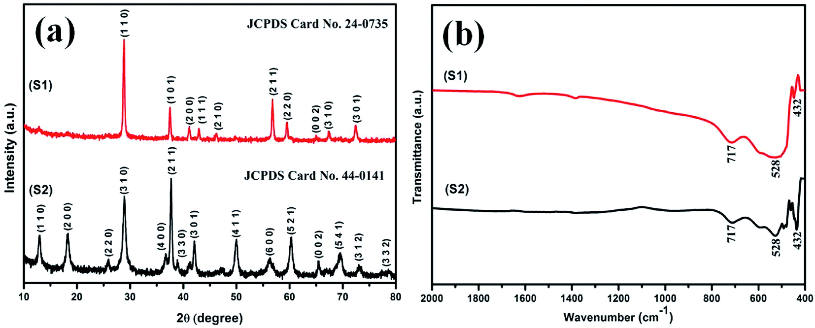 | ||
| Fig. 1 (a) XRD patterns and (b) FTIR spectroscopy of the samples S1 and S2 prepared using KMnO4 and NaNO2 in the molar ratio of 2:3 at a temperature of 160 °C for 12 h with H2SO4 in the molar concentration of 0.4 M and 0.3 M, respectively. | ||
Interestingly, there was a phase transition to α phase when the concentration of H2SO4 was reduced to 0.3 M, following the same synthesis procedures. It is apparent that MnO4− and NO2− coexisting with the corresponding H+ ions (eqn (A)) play a crucial role in our synthesis process to determine the crystal structure and morphology of the products. Few assumptions which can be made for the change of phase are detailed below. A certain amount of Mn4+ ions is required as stabilizing ions for the formation of tunnel structures. In our experiment, the decrease in H+ ions results in a decrease in the formation rate of Mn4+ or the growth unit [MnO6],69 which further accounts for a decrease in the formation rate of various crystal faces. This could be the viable reason for the formation of α phase of MnO2, as it has lower crystal faces due to the presence of larger [2 × 2] tunnel structures as against smaller [1 × 1] tunnel structures present in its β phase counterpart.69 However, a clear insight needs to be done in near future.
3.2 Functional group analysis
Infrared spectra of samples S1 and S2 are shown in Fig. 1(b). A common form in transmittance spectra is observed for both the samples. The common bands at around 715, 531 and 448 cm−1 can be referred to the metal–oxygen, Mn–O bonding vibrations.70 No other vibrating bands are present in samples, which reveals for their high purity and is consistent with the XRD analysis.3.3 Morphological analysis
The TEM and HRTEM images shown in Fig. 2(a)–(f) for α and β-MnO2 samples confirm their morphologies to be in one dimensional nanorods like shape with diameter in the range of 10–40 nm. The HRTEM image of α-MnO2 (see Fig. 2(c)) in growth direction of (310) suggests the d-spacing of 0.314 nm while that of β-MnO2 (see Fig. 3(f)) in growth direction of (101) indicates the d-spacing of 0.24 nm. Both the results match well with their respective JCPDS data. | ||
| Fig. 2 (a, b) TEM images of α-MnO2 at different magnifications, (c) HRTEM image of α-MnO2 with growth direction (310), d-spacing = 0.314 nm and EDX pattern as inset in (c). (d, e) TEM images of β-MnO2 at different magnifications, (f) HRTEM image of β-MnO2 with growth direction (101), d-spacing = 0.24 nm and EDX pattern as inset in (f). | ||
 | ||
| Fig. 3 FESEM images of the final product prepared using KMnO4 and NaNO2 in the molar ratio of 2:3 at a temperature of 160 °C for 12 h with H2SO4 in the molar concentration of (a) 1.3 M, (b) 1.2 M, (c) 0.9 M, (d) 0.6 M, (e) 0.4 M and (f) 0.3 M. | ||
Energy dispersive X-ray analysis (EDX) of α and β-MnO2 nanorods are presented in inset of Fig. 2(c) and (f), respectively. The presence of high intensity peaks for manganese and oxygen elements and the absence of any impurity peaks, indicates that the as-obtained α and β-MnO2 nanorods were in pure form with negligible impurities. The results are found in corollary with the XRD data.
For morphological analysis at different acid strengths, different samples were prepared. Fig. 1(a)–(f) shows the FESEM images of samples prepared under different molarities of 1.3, 1.2, 0.9, 0.6, 0.4 and 0.3 M H2SO4 respectively. FESEM image of the sample prepared with 1.3 M H2SO4 (Fig. 1(a)) clearly depicts the bulk morphology and rules out presence of any nanostructure. Microstructure in the form of microflakes with microsheets like morphology having thickness of 0.5–1 μm is conspicuous. As seen from Fig. 1(b), microrods like morphology are obtained instead of microsheets when H2SO4 content is decreased to 1.2 M. These microrods still resemble the bulk form due to high level of agglomerations and attachments. Microrods having diameters of about 0.3–1 μm with lesser agglomeration and increased finesse can be visualized for the sample prepared at further decreased acidic strength of 0.9 M. The agglomerations are found to be drastically reduced upon decreasing the amount of H2SO4 to 0.6 M (Fig. 1(c)) and ultrafine nanorods with diameter in the range of 50–150 nm are obtained. This predicts the possibility of achieving morphologies at nanoscale level by decrease in amount of acid concentration during the synthesis process. The formation of smaller dimensional MnO2 structures with slimmer forms was possible due to the restriction imposed on the redox reaction by the decrease in amount of protons (H2SO4) which eventually increases the reduction potential of permanganate ions based on the Nernst equation.71 Fortunately, the further decrease in H2SO4 content to 0.4 and 0.3 M leads to reduction in diameters of nanorods (Fig. 1(e) and (f)) and 1D nanorods with diameters in the range of 10–40 nm are formed. Hence, it can be predicted that as the surface energy of nanorods is very high compared to their bulk counterpart, they cannot withstand to form a stable structure under high acidic pressure. Only under optimized conditions with relatively less acidic effect, the probabilities of getting nanostructures are high. In conjugation with the XRD analysis, it is notable that at 0.4 M H2SO4, β-MnO2 nanorods exist and at 0.3 M H2SO4, α-MnO2 nanorods exist.
For studying the growth mechanism of nanorods, FESEM images were captured at different time intervals of 2 h, 5 h and 7 h (Fig. 4(a)–(c)), respectively for the sample prepared at 0.4 M H2SO4 (β-MnO2). It can be assumed that during the initial stage of hydrothermal reaction i.e. after 2 hours, the precursors disintegrates under extreme hydrothermal pressure and nucleates to form nanoparticles (Fig. 4(a)). When the reaction proceeds for 5 h, these nanoparticles self assembled to reduce the interfacial energies generated by their high surface areas and eventually coagulates to form dense mess of aggregated nanorods (Fig. 4(b)). When the reaction further proceeds for 7 h, the aggregated nanorods starts getting their individuality and are fine tuned (Fig. 4(c)). Finally at 12 h of reaction ultrafine nanorods having 10–40 nm diameter can be seen in Fig. 3(e). This can be accounted for the Kirkendall effect. The results are in line with our previous reports.72
 | ||
| Fig. 4 FESEM images of the sample prepared with 0.4 M H2SO4 at hydrothermal reaction time of (a) 2 h, (b) 5 h and (c) 7 h. | ||
3.4 DFT analysis
As Fig. 5 suggests, quasi-1D nanostructures of α- and β-MnO2 are structurally different, which is in good agreement with the HRTEM data (see Fig. 2(c) and (f)). Besides, the chemical potential of α-MnO2 is about 40% more than that of β-MnO2 (see Table 1). For finding the stability of free-standing structures, we resort to the wire tension (f) minima, as suggested by Tosatti et al.,73 such that| f = (F − ηN)/L, | (1) |
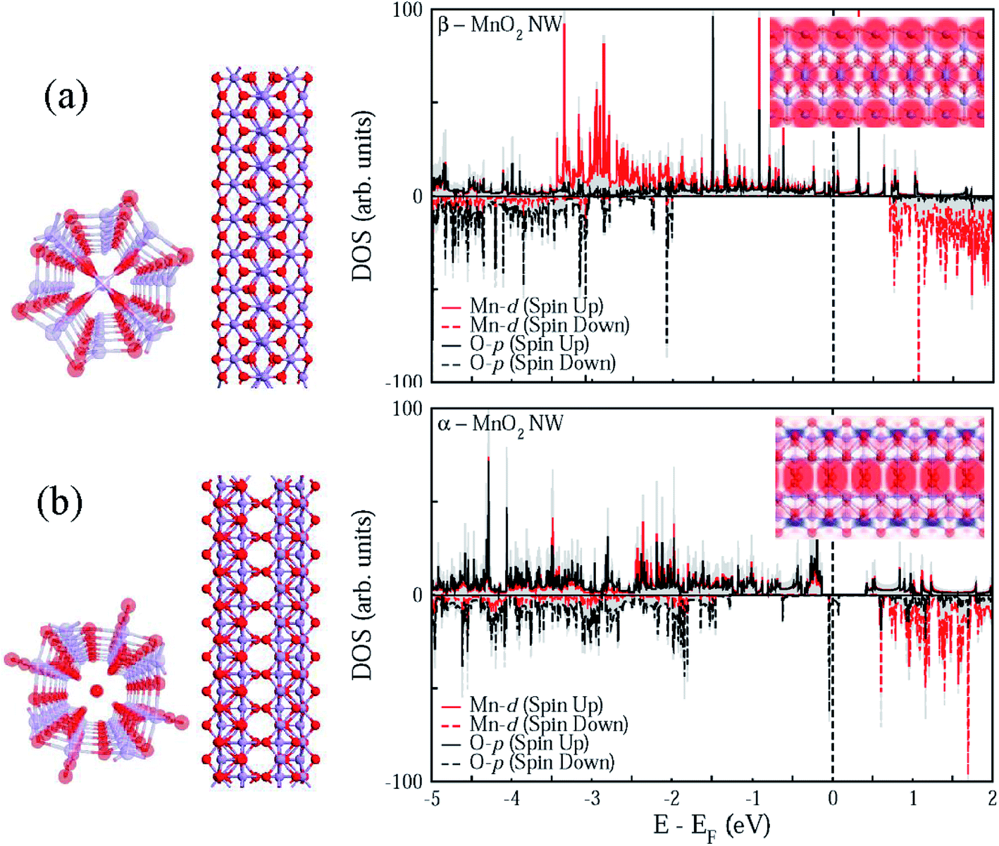 | ||
| Fig. 5 Calculated quasi-1D nanostructures (top as well as side view) and associated spin-polarized density of states for (a) β-MnO2 and (b) α-MnO2 phases. The electron density difference of each phase for up (red) and down (blue) spins is shown in the respective inset. | ||
| Mechanical properties | α-MnO2 nanorods | β-MnO2 nanorods |
|---|---|---|
| η (eV) | 5.69 | 3.98 |
| m (μB) | 1.04 | 1.95 |
| f (eV Å−1) | 2.6 | 1.8 |
| Σ (GPa−1) | 0.14 | 0.31 |
| G (GPa) | 4.5 | 2.0 |
| Y (GPa) | 139.5 | 38.9 |
| Vxy | −0.97 | −1.38 |
Additionally, Fig. 5 demonstrates that both the phases can exhibit the half-metallic character as well, often suitable for various device applications. However, the spin polarization is more intense along the central strand of α-MnO2 unlike the case with β-MnO2, where the spin polarization is spread almost all over. It goes well with the recent observation76 of surface metallicity in MnO2.
To further shed light on the mechanical properties, Table 1 enlists the calculated elastic constants for the two polymorphs of MnO2, based on which the compressibility (Σ), shear modulus (G), Young's modulus (Y), and Poisson's ratio (Vxy) were evaluated using the Voigt–Reuss–Hill averaging scheme.77 The compressibility can become just double while the shear modulus can drop close to even half the value for β-MnO2 in comparison with α-MnO2. Similarly, the calculated Young's modulus for α-MnO2 turns out to be as much as three times that of β-MnO2 in quasi-1D conformation.
A detailed study by Riedo et al.78 shows that the change in the friction coefficient of the samples is inversely related to the variations of their Young's modulus. This way, it can be predicted that quasi-1D α-MnO2 possesses lower coefficient of friction than β-MnO2. It further suggests that α-MnO2 should be a promising candidate as lubricant additive in comparison to β-MnO2, though the latter has better structural stability in reduced dimensions.
3.5 Tribological analysis
The coefficient of friction is calculated according to the following relation:
 | (2) |
 | ||
| Fig. 6 (a) Frictional torque with respect to time observed using four ball test technique, (b) coefficient of friction of pure palm oil β-MnO2 added palm oil and α-MnO2 added palm oil and (c) schematic outlay of the four-ball test rig. | ||
The results are also in line with the scar diameters as observed from the Fig. 7(a)–(c), which indicated that surface to surface contact in case of α-MnO2 (scar diameter 0.525 mm) is lower than that of β-MnO2 (scar diameter 0.535 mm) and pure palm oil (scar diameter 0.645 mm) (Fig. 7(d)). Error bars account for the average values obtained after three repeated experiments. The scar diameter in case of palm oil is comparable with the reported data (0.62 mm at 40 kgf load).35 The scar diameters in case of α-MnO2 and β-MnO2 nanorods as additives are found to be 7.9% and 6.14% lower than the reported data,35 which uses MoS2 nanoparticles as additives in base palm oil at similar condition. Lower scar diameter directly relates to lowering of wear rate in lubricant. Therefore, the nanorods as additives are expected to show better anti-wear properties.
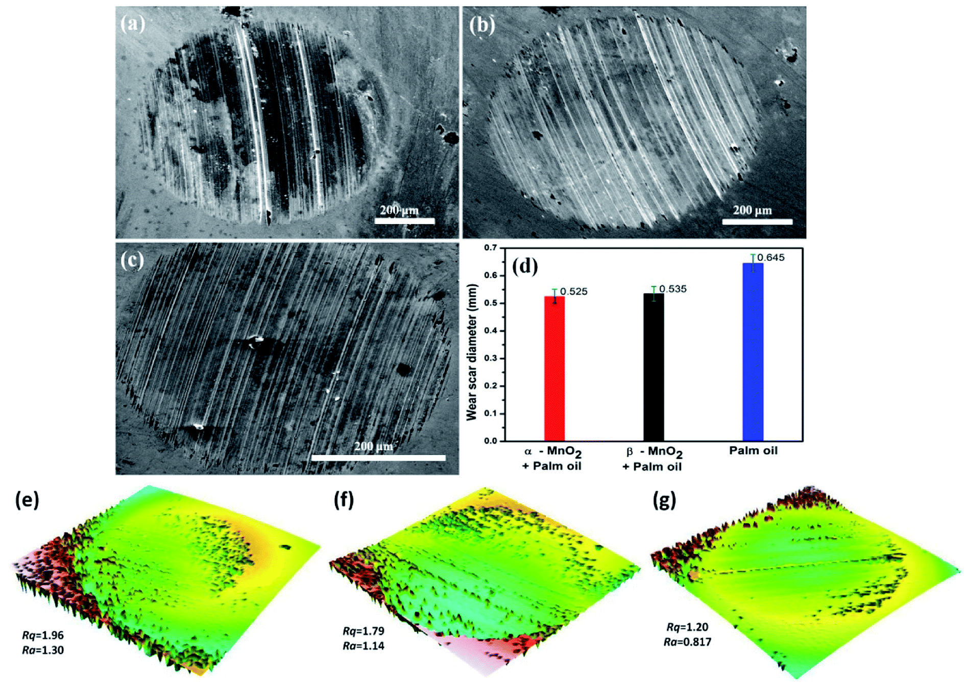 | ||
| Fig. 7 FESEM images of scar surfaces of the balls tested using (a) pure palm oil, (b) β-MnO2 added palm oil and (c) α-MnO2 added palm oil as lubricants and (d) their respective wear scar diameters. Three dimensional surface morphologies taken using profilometer with line roughness (Rq) and average roughness (Ra) values for balls tested using (e) pure palm oil, (f) β-MnO2 added palm oil and (g) α-MnO2 added palm oil as lubricants. | ||
Further insight into the frictional property through the theoretically calculated Young's modulus can be drawn from Bowden and Tabor theory,80 as given by
| f = τA, | (3) |
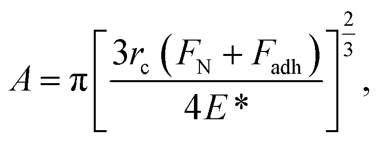 | (4) |
| f = μ(FN + Fadh) | (5) |
Thus, from eqn (4) and (5), we obtain
 | (6) |
From eqn (6), it can be observed that the frictional force is directly proportional to the forces applied and is inversely proportional to the Young's modulus of the contacting bodies. Since, α-MnO2 has higher Young's modulus than β-MnO2, the frictional force should also be lower in case of α-MnO2, as compared to β-MnO2.
α-MnO2 added palm oil showed better lubricity than β-MnO2 added palm oil. This is in agreement with the results observed from the scar diameter and coefficient of friction values. Fig. 8(a) and (b) shows the presence of α-MnO2 nanorods while Fig. 8(c) and (d) shows the presence of β-MnO2 nanorods on the scars of tested balls with morphological variations in the nanometer range. Nanorods possessing 1D structure were able to penetrate easily into the intrinsic parts of the contact areas by filling up the small fissures and holes in the rubbing surfaces through the mending effect. A schematic of the mechanism responsible for lowering the coefficient of friction is portrayed in Fig. 8(e). The anchoring behaviour of MnO2 initiated the formation of in situ films which restricted the metal to metal contact, thus, arresting the asperity–asperity contact. As a consequence, nanorods were supposed to form protective layers above the rubbing surfaces which were smoothened enough to exhibit the low coefficient of friction.
 | ||
| Fig. 8 FESEM images of the deposited nanorods on the scar surfaces of balls tested using (a, b) α-MnO2 added palm oil with FESEM image of α-MnO2 nanorods as inset in (b), (c, d) β-MnO2 added palm oil with FESEM image of β-MnO2 nanorods as inset in (d) and (e) schematic of the mechanisms responsible for enhancement of antiwear property of the base oil by nanorods. | ||
In view of nanoscience, a deeper insight can be presumed for the lowering of coefficient of friction with addition of nanorods. It is clear that the additives used were 1D nanostructure and so they must have experienced confinement in density of states by degeneracy of energy levels. This could have increased density of electrons on to the surface, which were confined to move only in one dimension thereby increasing the surface energy. This confined one dimensional movement might have increased the mobility of these high energy electrons which could have developed enough kinetic energy that adds up in the movement of balls and thus helped in decreasing the coefficient of friction.
The FESEM images, as shown in Fig. 8(c) and (d), reveal the noticeable morphological changes in the β-MnO2 nanorods as compared to α-MnO2 nanorods, as shown in Fig. 8(a) and (b). It is evident that the diameter of β-MnO2 nanorods rose to 80–100 nm range from 10–50 nm range (approximately) after experiencing the anti-wear test. However, in the case of α-MnO2 nanorods, there was no noticeable difference in the morphology even after the test. This reveals that α-MnO2 nanorods have better elastic properties and superior shock absorbing capabilities in comparison with β-MnO2 nanorods.
4 Conclusions
Ultrafine one dimensional α and β-MnO2 nanorods with diameters of about 10–40 nm were successfully obtained by one-pot synthesis. Phase of the MnO2 nanorods was effectively controlled by altering the molar concentration of H2SO4 at the start of hydrothermal reaction. The work suggests that the nanostructures can exist in relatively low acidic conditions than compared with bulk counterpart. We have explored the tribological aspects of two well-known polymorphic phases of MnO2 in quasi-1D form. The as prepared nanorods are found to considerably enhance the lubricity of the base oil. We observe that even a reduction of as high as 30% in the coefficient of friction can happen when α-MnO2 nanorods are exploited as nanoadditives in a biodegradable lubricant such as palm oil. The right interplay between the rolling action and the mending effect may be attributed to be the principal mechanism behind such augmentation of the antiwear properties of the base oil, once added with MnO2 nanorods. Although β-MnO2 nanorods are structurally more stable than β-MnO2 nanorods, the latter come out to be less susceptible to any morphological changes during the antiwear test. Our first principles elasticity analysis reveals that α-MnO2 nanorods can be better additives than β-MnO2 nanorods due primarily to superior elastic properties of the former. This work has established that the polymorphic quasi-1D MnO2 nanostructures can well be used as effective nanolubricant additives in future.Acknowledgements
This work was supported by DST Nano Mission, Govt. of India, via Project No. SR/NM/NS-1062/2012. We are thankful to the National PARAM Supercomputing Facility (NPSF), Centre for Development of Advanced Computing (C-DAC), India, and SRMHPCC for facilitating the high-performance computing.References
- T. Zordan and L. G. Hepler, Chem. Rev., 1968, 68, 737–745 CrossRef CAS.
- G. Gnanakumar, Z. Awan, K. Nahm and J. Xavier, Biosens. Bioelectron., 2014, 53, 528–534 CrossRef CAS PubMed.
- T. Gao, H. Fjellvåg and P. Norby, Nanotechnology, 2009, 20, 055610 CrossRef PubMed.
- J. E. Post, Proc. Natl. Acad. Sci. U. S. A., 1999, 96, 3447–3454 CrossRef CAS.
- S. Chen, J. Zhu and X. Wang, ACS Nano, 2010, 4, 6212–6218 CrossRef CAS PubMed.
- L. Feng, Z. Xuan, H. Zhao, Y. Bai, J. Guo, C.-w. Su and X. Chen, Nanoscale Res. Lett., 2014, 9, 1 CrossRef CAS PubMed.
- L.-L. Yu, J.-J. Zhu and J.-T. Zhao, J. Mater. Chem. A, 2014, 2, 9353–9360 CAS.
- W. Tang, Y. Hou, X. Wang, Y. Bai, Y. Zhu, H. Sun, Y. Yue, Y. Wu, K. Zhu and R. Holze, J. Power Sources, 2012, 197, 330–333 CrossRef CAS.
- Y. Yang, L. Xiao, Y. Zhao and F. Wang, Int. J. Electrochem. Sci., 2008, 3, 67–74 CAS.
- Y.-C. Chen, Y.-K. Hsu, Y.-G. Lin, Y.-K. Lin, Y.-Y. Horng, L.-C. Chen and K.-H. Chen, Electrochim. Acta, 2011, 56, 7124–7130 CrossRef CAS.
- W. Wei, X. Cui, W. Chen and D. G. Ivey, Chem. Soc. Rev., 2011, 40, 1697–1721 RSC.
- P. Yu, X. Zhang, D. Wang, L. Wang and Y. Ma, Cryst. Growth Des., 2008, 9, 528–533 Search PubMed.
- V. Subramanian, H. Zhu, R. Vajtai, P. Ajayan and B. Wei, J. Phys. Chem. B, 2005, 109, 20207–20214 CrossRef CAS PubMed.
- X. Li, B. Hu, S. Suib, Y. Lei and B. Li, Biochem. Eng. J., 2011, 54, 10–15 CrossRef CAS.
- T. T. Truong, Y. Liu, Y. Ren, L. Trahey and Y. Sun, ACS Nano, 2012, 6, 8067–8077 CrossRef CAS PubMed.
- Y. Yuan, H. Li, M. Luo, S. Qin, W. Luo, L. Li and H. Yan, Water, Air, Soil Pollut., 2014, 225, 1–9 CAS.
- Y. Hou, Y. Cheng, T. Hobson and J. Liu, Nano Lett., 2010, 10, 2727–2733 CrossRef CAS PubMed.
- J. B. Fei, Y. Cui, X. H. Yan, W. Qi, Y. Yang, K. W. Wang, Q. He and J. B. Li, Adv. Mater., 2008, 20, 452–456 CrossRef.
- J. Cao, Q. Mao, L. Shi and Y. Qian, J. Mater. Chem., 2011, 21, 16210–16215 RSC.
- W. Zhang, C. Zeng, M. Kong, Y. Pan and Z. Yang, Sens. Actuators, B, 2012, 162, 292–299 CrossRef CAS.
- J.-J. Feng, P.-P. Zhang, A.-J. Wang, Y. Zhang, W.-J. Dong and J.-R. Chen, J. Colloid Interface Sci., 2011, 359, 1–8 CrossRef CAS PubMed.
- B. B. Lakshmi, C. J. Patrissi and C. R. Martin, Chem. Mater., 1997, 9, 2544–2550 CrossRef CAS.
- D. Zitoun, N. Pinna, N. Frolet and C. Belin, J. Am. Chem. Soc., 2005, 127, 15034–15035 CrossRef CAS PubMed.
- J. C. Villegas, L. J. Garces, S. Gomez, J. P. Durand and S. L. Suib, Chem. Mater., 2005, 17, 1910–1918 CrossRef CAS.
- Y.-S. Ding, X.-F. Shen, S. Sithambaram, S. Gomez, R. Kumar, V. M. B. Crisostomo, S. L. Suib and M. Aindow, Chem. Mater., 2005, 17, 5382–5389 CrossRef CAS.
- M.-S. Wu, J.-T. Lee, Y.-Y. Wang and C.-C. Wan, J. Phys. Chem. B, 2004, 108, 16331–16333 CrossRef CAS.
- B. N. Rao, P. Muralidharan, P. R. Kumar, M. Venkateswarlu and N. Satyanarayana, Int. J. Electrochem. Sci., 2014, 9, 1207–1220 Search PubMed.
- J. G. Zhao, J. Z. Yin and S. G. Yang, Mater. Res. Bull., 2012, 47, 896–900 CrossRef CAS.
- W. Tang, Y. Hou, X. Wang, Y. Bai, Y. Zhu, H. Sun, Y. Yue, Y. Wu, K. Zhu and R. Holze, J. Power Sources, 2012, 197, 330–333 CrossRef CAS.
- D. Su, H. J. Ahn and G. Wang, J. Mater. Chem. A, 2013, 1, 4845–4850 CAS.
- J. Chen, Y. Wang, X. He, S. Xu, M. Fang, X. Zhao and Y. Shang, Electrochim. Acta, 2014, 142, 152–156 CrossRef CAS.
- K. Ramachandran, A. Zahoor, T. Kumar, K. Nahm, A. Balasubramani and G. Kumar, J. Ind. Eng. Chem., 2017, 46, 19–27 CrossRef CAS.
- N. Kumar, P. Dineshkumar, R. Rameshbabu and A. Sen, Mater. Lett., 2015, 158, 309–312 CrossRef CAS.
- N. Kumar, P. Dineshkumar, R. Rameshbabu and A. Sen, RSC Adv., 2016, 6, 7448–7454 RSC.
- M. Gulzar, H. Masjuki, M. Varman, M. Kalam, R. Mufti, N. Zulkifli, R. Yunus and R. Zahid, Tribol. Int., 2015, 88, 271–279 CrossRef CAS.
- P. S. Lathi and B. Mattiasson, Appl. Catal., B, 2007, 69, 207–212 CrossRef CAS.
- M. Fazal, A. Haseeb and H. Masjuki, Energy Convers. Manage., 2013, 67, 251–256 CrossRef CAS.
- N. Kumar and S. Chauhan, et al., Proc. Inst. Mech. Eng., Part J, 2014, 228, 797–807 CrossRef CAS.
- N. Fox and G. Stachowiak, Tribol. Int., 2007, 40, 1035–1046 CrossRef CAS.
- N. Zulkifli, M. Kalam, H. Masjuki, M. Shahabuddin and R. Yunus, Energy, 2013, 54, 167–173 CrossRef CAS.
- H. Huang, J. Tu, T. Zou, L. Zhang and D. He, Tribol. Lett., 2005, 20, 247–250 CrossRef CAS.
- G. Liu, X. Li, B. Qin, D. Xing, Y. Guo and R. Fan, Tribol. Lett., 2004, 17, 961–966 CrossRef CAS.
- L. Sun, Z. Zhang, Z. Wu and H. Dang, Mater. Sci. Eng., A, 2004, 379, 378–383 CrossRef.
- C. Grossiord, J. Martin, T. Le Mogne and T. Palermo, Surf. Coat. Technol., 1998, 108, 352–359 CrossRef.
- M. Charoo and M. F. Wani, Tribol. Ind., 2016, 38, 156–162 Search PubMed.
- M. Kandeva, D. Karastoianov, B. Ivanova and V. Pojidaeva, Proceedings of the 13th International Conference on Tribology–SERBIATRIB'13, Kragujevac, Serbia, 2013, pp. 31–36 Search PubMed.
- L. Rapoport, V. Leshchinsky, M. Lvovsky, O. Nepomnyashchy, Y. Volovik and R. Tenne, Ind. Lubr. Tribol., 2002, 54, 171–176 CrossRef.
- Y. Wu, W. Tsui and T. Liu, Wear, 2007, 262, 819–825 CrossRef CAS.
- F. Chinas-Castillo and H. Spikes, J. Tribol., 2003, 125, 552–557 CrossRef CAS.
- Z. S. Hu, R. Lai, F. Lou, L. Wang, Z. Chen, G. Chen and J. Dong, Wear, 2002, 252, 370–374 CrossRef CAS.
- Z. Xiaodong, F. Xun, S. Huaqiang and H. Zhengshui, Lubr. Sci., 2007, 19, 71–79 CrossRef.
- B. Ginzburg, L. Shibaev, O. Kireenko, A. Shepelevskii, M. Baidakova and A. Sitnikova, Russ. J. Appl. Chem., 2002, 75, 1330–1335 CrossRef CAS.
- J. Zhou, J. Yang, Z. Zhang, W. Liu and Q. Xue, Mater. Res. Bull., 1999, 34, 1361–1367 CrossRef CAS.
- L. Zhang, J. Tu, H. Wu and Y. Yang, Mater. Sci. Eng., A, 2007, 454, 487–491 CrossRef.
- J. Yang, H. Yao, Y. Liu and Y. Zhang, Nanoscale Res. Lett., 2008, 3, 481 CrossRef CAS PubMed.
- K. Panda, N. Kumar, K. Sankaran, B. Panigrahi, S. Dash, H.-C. Chen, I.-N. Lin, N.-H. Tai and A. Tyagi, Surf. Coat. Technol., 2012, 207, 535–545 CrossRef CAS.
- C. Liu, H. Yan, Z. Chen, L. Yuan and T. Liu, J. Mater. Chem. A, 2015, 3, 10559–10565 CAS.
- S. Bhaumik, S. Datta and S. D. Pathak, J. Tribol., 2017, 139(6), 061802 CrossRef.
- J. Hershberger, O. Ajayi and G. Fenske, Scr. Mater., 2005, 53, 1449–1453 CrossRef CAS.
- L. Joly-Pottuz, F. Dassenoy, M. Belin, B. Vacher, J. Martin and N. Fleischer, Tribol. Lett., 2005, 18, 477–485 CrossRef CAS.
- F. Dalla Torre, H. Van Swygenhoven, R. Schäublin, P. Spätig and M. Victoria, Scr. Mater., 2005, 53, 23–27 CrossRef CAS.
- P. Hu, Y. Liu, L. Fu, X. Wang and D. Zhu, Appl. Phys. A: Mater. Sci. Process., 2005, 80, 35–38 CrossRef CAS.
- Z. Li, X. Tao, Y. Cheng, Z. Wu, Z. Zhang and H. Dang, Mater. Sci. Eng., A, 2005, 407, 7–10 CrossRef.
- F. Ilie and C. Covaliu, Lubricants, 2016, 4, 12 CrossRef.
- A. Dongare and G. Vikhe Patil, Int. J. Eng. Res. Dev., 2012, 6–11 Search PubMed.
- Atomistix ToolKit version 2015.1, http://www.quantumwise.com Search PubMed.
- M. Brandbyge, J.-L. Mozos, P. Ordejón, J. Taylor and K. Stokbro, Phys. Rev. B: Condens. Matter Mater. Phys., 2002, 65, 165401 CrossRef.
- R. Yu, J. Zhu and H. Ye, Comput. Phys. Commun., 2010, 181, 671–675 CrossRef CAS.
- X. Wang and Y. Li, J. Am. Chem. Soc., 2002, 124(12), 2880–2881 CrossRef CAS PubMed.
- Y.-J. Huang and W.-S. Li, J. Inorg. Mater., 2013, 28, 341–346 CrossRef CAS.
- C. M. McShane and K.-S. Choi, J. Am. Chem. Soc., 2009, 131, 2561–2569 CrossRef CAS PubMed.
- N. Kumar, A. Sen, K. Rajendran, R. Rameshbabu, J. Ragupathi, H. Therese and T. Maiyalagana, RSC Adv., 2017, 7, 25041 RSC.
- E. Tosatti, S. Prestipino, S. Kostlmeier, A. D. Corso and F. D. Di Tolla, Science, 2001, 291, 288–290 CrossRef CAS PubMed.
- D. A. Tompsett, S. C. Parker and M. S. Islam, J. Am. Chem. Soc., 2014, 136, 1418–1426 CrossRef CAS PubMed.
- Y. Yuan, S. M. Wood, K. He, W. Yao, D. Tompsett, J. Lu, A. Nie, M. S. Islam and R. Shahbazian Yassar, ACS Nano, 2016, 10, 539–548 CrossRef CAS PubMed.
- D. A. Tompsett and M. S. Islam, J. Phys. Chem. C, 2014, 118, 25009–25015 CAS.
- R. Hill, Proc. Phys. Soc., London, Sect. A, 1952, 65, 349 CrossRef.
- E. Riedo and H. Brune, Appl. Phys. Lett., 2003, 83, 1986–1988 CrossRef CAS.
- M. Shaari, N. Roselina, S. Kasolang, K. Hyie, M. Murad and M. Bakar, J. Teknol., 2015, 76(9), 69–73 Search PubMed.
- F. P. Bowden and D. Tabor, Friction and Lubrication of solids, Part 1, Oxford University Press, New York, 1950 Search PubMed.
- K. Johnson, Contact Mechanics, Cambridge University Press, Cambridge, 1987 Search PubMed.
- B. Persson, Sliding friction: Physical principles and applications, Springer, Berlin, 2nd edn, 2000 Search PubMed.
| This journal is © The Royal Society of Chemistry 2017 |