DOI:
10.1039/C7RA04331G
(Paper)
RSC Adv., 2017,
7, 32357-32366
Fabrication of a new biosensor based on a Sn doped ceria nanoparticle modified glassy carbon paste electrode for the selective determination of the anticancer drug dacarbazine in pharmaceuticals†
Received
18th April 2017
, Accepted 12th June 2017
First published on 26th June 2017
Abstract
A new tin doped ceria nanoparticle modified glassy carbon paste electrode (Sn–CeO2NPs/GCPE) was fabricated for the determination of the anticancer drug dacarbazine (DTIC). The Sn–CeO2 nanoparticles with Sn concentrations from 0 to 10 wt% were synthesized by sol gel method. Sn doped CeO2 nanoparticles were characterized by X-ray diffraction, energy-dispersed X-ray spectrometry (EDS) and transmission electron microscopy (TEM). Cyclic voltammetry (CV) and square wave voltammetry (SWV) were applied to investigate the unique properties of the Sn–CeO2NPs/GCPE. The modified electrode showed an excellent character for electrocatalytic oxidization of DTIC, while the bare GCPE electrode only gave a small oxidation peak. The fabricated sensor showed an excellent anti-interference ability against electroactive species and metal ions. This modified electrode was used as a sensor for determination of DTIC in human biological fluids and in pharmaceutical samples with satisfactory results.
1. Introduction
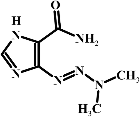
The detection and quantification of electrochemically active compounds such as the anticancer drug dacarbazine in biological fluids like blood and urine are important to diagnose and monitor several diseases, besides supplying information about the interactions involving these species in the physiological processes. Dacarbazine [5-(3,3-dimethyl-l-triazenyl)imidazole-4-carboxamide] (DTIC) (Scheme 1) is an important antitumor agent with a proven activity and selectivity against various types of malignant diseases, such as soft tissue sarcoma and lung carcinoma. It has also been used in combination with other medications for treating Hodgkin's lymphoma.l,2 Dacarbazine is a member of the class of alkylating agents, which destroy cancer cells by adding an alkyl group to their DNA. The widespread use of dacarbazine and the need for clinical and pharmaceutical studies require fast and sensitive analytical techniques to determine this drug in a variety of biological fluids and in quality control.3,4
 |
| | Scheme 1 Structure of DTIC. | |
Several time consuming and expensive techniques for detection of DTIC have been studied and reported, which include chromatography5–7 and spectrometry.8 One of the broadly exercised simple, swift, and exact methods is electrochemical method. There are few reported electrochemical methods, have been applied for the determination of DTIC.9–11 Among all the above, electrochemical methods have shown remarkable advantages in the analysis of drugs in pharmaceutical preparations and human body fluids. These advantages are mainly due to the simplicity, low cost and relatively short analysis times of these compounds as compared to the other routine analytical techniques including chromatography.12,13 Further handling this technique requires a knowledge regarding the working electrode, where the electrode reactions are centered. Relatively a newly adopted method for the improvement of analyte and surface interaction is the modification of the electrode surface. For the modification of electrode surface, varieties of methods are used which include, nanoparticle incorporation on the surface of the electrode. Unique characters and vast potential application in nanodevice fabrication nanomaterials have engrossed, broad notice.14–16
Nanostructured metal oxides such as ZnO, Fe3O4, SnO2, CeO2, In2O3 and others have recently aroused much interest as immobilizing matrices for chemo-biosensor development due to their interesting nanomorphological, functional, biocompatible and catalytic properties.17–20 Further chemical doping with appropriate elements (Fe, Cr, Co, Mn, Ni, etc.) is widely used as an effective method to tune surface states, energy levels of semiconductors and transport performance of carriers, and enhance the electrical, electrochemical and magnetic properties of materials.21–27 Among these, the design of CeO2 nanomaterials with controlled morphologies is of special interest due to their favorable shape-dependent properties.28–30 Different strategies are adopted to improve the physico-chemical properties and morphology of the nanostructured CeO2 in order to achieve high sensitivity and selectivity. Recently, metal-doped ceria nanomaterials have been widely considered to promote the active oxygen content on ceric oxide nanoparticles (CeO2NPs) surface by changing the surface element composition, because such materials ultimately reveal strikingly high catalytic activity.31 Chemical doping into CeO2 matrix with appropriate dopants (B or In) at Ce4+ site is proved to be highly effective for chemo-biosensing applications.32,33 The added active elements stabilize the CeO2 surface, and promote a decrease in grain size which enhances higher catalytic activity and sensor response than that of pure CeO2. Hence in this work, a novel Sn–CeO2NPs modified glassy carbon microspheres paste electrode (Sn–CeO2NPs/GCPE) was prepared and applied for selective and sensitive electrochemical determination of DTIC without physiological interferents.
2. Experimental
2.1. Chemicals
DTIC, cerium(III) nitrate hydrate, ten chloride pentahydrate and polyvinylalcohol polymer (PVA) (MW = 30![[thin space (1/6-em)]](https://www.rsc.org/images/entities/char_2009.gif) 000 g mol−1), were purchased from Sigma-Aldrich chemicals (St.Louis, Mo, USA). Glassy carbon spherical microparticles with a diameter of 0.4–12 μm and mineral oil were obtained from Alfa Aesar (Ward Hill, MA). A stock solution of DTIC (1 × 10⁻³ M) was prepared by dissolving an appropriate amount of the drug in ultrapure water and storing the solution in the dark at 4 °C. Electrochemical cells and volumetric flasks were protected from light by means of aluminium foil to avoid DTIC photodecomposition. Phosphate buffer solution (PBS) was prepared from NaH2PO4 and Na2HPO4 (0.2 M) and adjusted the pH with 0.1 M H3PO4 or NaOH solution. The pH values of the buffer solutions were measured with a digital radiometer pH meter, Jenway 3310 accurate to ±0.02 unit. Ultrapure water (Milli-pore Inc., 18.2 MΩ cm) was obtained from a Milli-Q purification system and used in all experiments.
000 g mol−1), were purchased from Sigma-Aldrich chemicals (St.Louis, Mo, USA). Glassy carbon spherical microparticles with a diameter of 0.4–12 μm and mineral oil were obtained from Alfa Aesar (Ward Hill, MA). A stock solution of DTIC (1 × 10⁻³ M) was prepared by dissolving an appropriate amount of the drug in ultrapure water and storing the solution in the dark at 4 °C. Electrochemical cells and volumetric flasks were protected from light by means of aluminium foil to avoid DTIC photodecomposition. Phosphate buffer solution (PBS) was prepared from NaH2PO4 and Na2HPO4 (0.2 M) and adjusted the pH with 0.1 M H3PO4 or NaOH solution. The pH values of the buffer solutions were measured with a digital radiometer pH meter, Jenway 3310 accurate to ±0.02 unit. Ultrapure water (Milli-pore Inc., 18.2 MΩ cm) was obtained from a Milli-Q purification system and used in all experiments.
2.2. Instrumentation
Cyclic voltammetry (CV) and square-wave voltammetry (SWV) were performed using an EG&G PAR 384 B (Princeton Applied Research, Oak Ridge, TN, USA) polarographic analyzer controlled by 394 software in conjunction with a PAR Model 303A. The electrode system consisted of the glassy carbon paste electrode (unmodified or modified) as the working electrode, a Ag/AgCl (saturated KCl) reference electrode and a Pt wire auxiliary electrode. A PAR Model 305 stirrer was used for SWV. For anodic stripping experiments an accumulation potential (Eacc) was applied for a certain accumulation time (ta), while the solution was stirred at 400 rpm. At the end of the accumulation period the stirrer was stopped and the solution was allowed to become quiescent for 15 s prior of the voltammetric scan. The surface morphology of the samples is analyzed by transmission electron microscopy, TEM (FEI, TECNAI, G2 spirit twin) using an accelerating voltage of 120 kV. Specimens for TEM are prepared by ultrasonic dispersion of some powder sample in ethanol and putting a droplet of the suspension on a copper microscope grid covered with carbon.
2.3. Preparation of Sn–CeO2NPs and CeO2NPs
In the present study, Sn doped CeO2NPs was synthesized by the sol–gel combustion hybrid method using PVA as a fuel. First, the PVA bulk solution was prepared by dissolving 20 g of PVA powder in 500 mL distilled water at 90 °C and continuous stirring for 3 h before left to cool at room temperature. Subsequently, 5 g cerium(III) nitrate hydrate and tin chloride (5 and 10 wt per %) were added into 100 mL PVA solution and stirred continuously for 6 h. The obtained sol was slowly heated to evaporate the solvent and it forms a hard homogeneous gel. The pyrrolysis of the final gel was performed at a temperature of 800 °C for 4 hours. During the pyrrolysis process the PVA polymeric network through the outer surface, cerium nitrate salt and tin chloride simultaneously calcinated and converted into Sn doped CeO2NPs (Sn–CeO2NPs). The obtained sample was crushed to prepare a fine powder. The CeO2NPs were prepared using the same procedure without adding tin chloride into the synthesis process. Characterizations of the obtained nanoparticles are done by XRD, EDS and TEM. XRD patterns of the undoped CeO2NPs and Sn doped CeO2NPs were recorded using a Bruker AXS D8 advanced diffractometer with Cu Kα radiation (λ = 1.5406 Å) in the range of 20–80°.The average crystallite sizes were calculated using Debye Scherrer formula:
| D = Kλ/βcosθ |
where K is the shape factor whose value is taken as 0.89, λ is the wavelength of Cu, Kα radiation, and β is the corrected full width at half maximum (FWHM) of the diffraction peak and θ is the diffracting angle.
2.4. Electrode preparation and modification
The unmodified glassy carbon paste electrode (GCPE) was prepared with the composition of 75:25 (glassy carbon powder:paraffin oil) using a mortar and pestle and allowed to undergo self-homogenization. The paste was packed firmly into the cavity of a Teflon tube (3 mm diameter) to a depth of 6 mm, and an electrical contact was achieved via a copper wire. The surface of the resulting paste electrode was smoothed and rinsed carefully with double distilled water. The undoped CeO2NPs/GCPE was prepared by mixing the optimal amount of glassy carbon powder, paraffin oil and CeO2NPs (75:15:10 w/w). The modified Sn–CeO2NPs/GCPE was fabricated by mixing of (75:15:10 w/w) ratio of glassy carbon/paraffin oil/Sn–CeO2NPs. Whenever necessary a new surface was obtained by pushing out an excess of paste and polish it on paper. Therefore the main advantages of the newly fabricated electrode are that the technique for its preparation is simple and require only short periods of time. In addition, the prepared modified electrode is renewable and low in cost compared to the literature methods. Nevertheless the materials for fabrication of the modified electrode are cheap and commercially available.
2.5. Preparation and analysis of real samples
Human serum and urine samples were obtained from healthy volunteers at the Hospital of Assiut University and stored in refrigerator immediately after collection before used. Ten milliliters of the urine sample was centrifuged for 30 min at 3000 rpm. The supernatant was filtered out using 0.45 μm Millipore filter and then diluted 50 times with PBS of pH 4. The solution was transferred into the voltammetric cell to be analyzed without any further pretreatment. One milliliter of the serum sample was treated with 5 mL of methanol and centrifuged at 4000 rpm for 20 min to remove the precipitating materials. Afterwards the separated serum was attenuated 10-fold with pH 4.0 phosphate buffer solutions. Then, 2.0 mL of this test solution was transferred into the electrochemical cell to determine DTIC by SWV method.
Dacarbazine vial labelled to contain 200 mg DTIC per vial was used as samples. The composition of the investigated DTIC vial was dacarbazine (42%), mannitol (16%) and citric acid monohydrate (42%). A weight portion of the powder content equivalent to 1 × 10⁻³ M of DTIC was transferred into a 25 mL calibrated flask and filled to the volume with ultrapure water and stored in dark at 4 °C. SWV measurements were performed using the standard addition method.
3. Results and discussion
3.1. XRD, EDS and TEM analysis of CeO2NPs and Sn-doped CeO2NPs
The structural properties of the undoped CeO2 and Sn (5 wt%) doped CeO2 nanoparticles were investigated by powder XRD method (Fig. 1A). It is clear that the diffraction peaks of all the samples correspond to the (111), (200), (220) and (311) planes that can be indexed to the cubic fluorite structure of CeO2 crystals. No characteristic peaks related to Sn and impurity peaks appear in XRD patterns in comparison with the standard XRD patterns of bulk CeO2 (JCPDS card No. 04-016-6759) which show that all Sn atoms have entered into CeO2 lattice. However, upon increasing the tin content, a moderate decrease in the intensity of diffraction peaks, accompanied by a pronounced broadening, has been observed. This can be attributed to the decrease of particle size, doping of CeO2 with Sn through the formation of a Sn–Ce solid solution and/or to induced microstrain.34 This is consistent with the fact that the ionic radius of Sn4+ (0.74 Å) is smaller than that of Ce4+ (0.97 Å). The XRD results showed that the Sn4+ ions incorporate into CeO2 lattice or replace Ce4+ sites without changing the cubic fluorite structure. The average crystallite sizes evaluated by the Scherrer equation were found to be 30 and 16.56 nm for undoped CeO2 and 5 wt% Sn doped CeO2 nanoparticles, respectively, suggesting that the grain growth is suppressed due to doping of Sn into Ce-site.
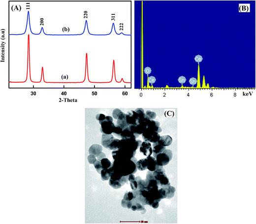 |
| | Fig. 1 (A) XRD patterns of (a) undoped CeO2NPs and (b) 5 wt% Sn doped CeO2NPs, EDX spectra (B), TEM image (C) of 5% Sn doped CeO2NPs. | |
To assess the elemental composition of Sn–CeO2, the EDS analysis was done and the result is shown in Fig. 1B. In EDS spectrum, numerous well-defined peaks were evident related to Sn, O and Ce which clearly support that the existence of Sn ions in doped sample and confirmed the successful doping of Sn in CeO2. The obtained results are in good agreement with XRD.
The TEM image of 5% Sn doped CeO2 was shown in Fig. 1C. The morphology of the Sn doped CeO2 nanoparticles was uniform with well-distributed elliptical/spherical particles with average particle size of about 17.23 nm, which is consistent with the results obtained from XRD. Most of the nanoparticles were well separated, although some of them partially aggregated. Therefore, the particle size of the samples obtained from TEM pattern was quite similar to those calculated from Scherrer's equation.
3.2. Morphological characterization of 5% Sn–CeO2NPs/GCPE
Fig. 2 compares the morphological features of GCPE and 5% Sn–CeO2NPs/GCPE using SEM. Significant differences in the surface structure of two electrodes were observed. The SEM profile of GCPE (Fig. 2A) was characterized by a surface of non-porous spherically shaped glassy carbon powder. Despite the presence of the mineral oil, the glassy carbon microspheres were packed in close proximity, and no defined binder regions were visible. Apparently, the oil fills the voids between the GC spheres, while holding them together. The glassy carbon microspheres clearly decorated with Sn–CeO2NPs. Besides the close packing arrangement of glassy carbon microspheres, a mass of Sn–CeO2NPs was filled in the gaps among the microspheres (Fig. 2B).
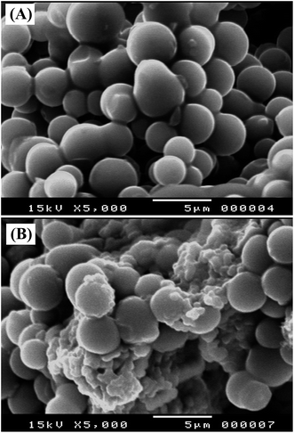 |
| | Fig. 2 SEM images of (A) GCPE and (B) 5% Sn doped CeO2NPs/GCPE. | |
3.3. Electrochemical activities of modified electrodes
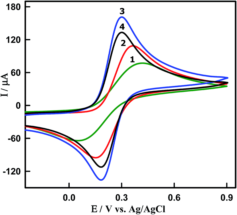
Electrochemical properties of modified electrodes were investigated using [Fe(CN)6]3−/4− as redox probes by cyclic voltammetry (Fig. 3). The cyclic voltammograms (CVs) were recorded in the presence of 5 mM [Fe(CN)6]3−/4− in 0.1 M KCl at the scan rate 100 mV s−1 for (curve 1) bare GCPE, (curve 2) CeO2NPs/GCPE and (curves 3 and 4) Sn–CeO2NPs/GCPE modified electrodes. At bare GCPE (curve 1), a pair of redox peaks were observed with a high capacitive background current, large peak to peak potential separation (ΔEP = 347 mV), and broadened wave shape. The ΔEP values for the undoped CeO2NPs (curve 2), 5 wt% (curve 3) and 10 wt% (curve 4) Sn doped CeO2NPs modified electrodes were found to be 206, 116 and 116 mV, respectively (Table 1). The undoped CeO2NPs modified GCPEs showed larger ΔEP value compared to that of the 5 wt% and 10 wt% Sn doped CeO2NPs modified GCPEs. The large peak separation was assumed to result from the lower electrical conductivity.
 |
| | Fig. 3 CVs of 5 mM [Fe(CN)6]3−/4− in 0.1 M KCl obtained at a scan rate of 0.10 V s−1. Curve 1: bare GCPE, curve 2: undoped CeO2NPs/GCPE, curve 3: 5% and curve 4: 10% Sn–CeO2NPs/GCPE. | |
Table 1 Electrochemical data of 5 mM [Fe(CN)6]3−/4− in 0.1 M KCl at different working electrodes
| Electrodes |
ΔEP (mV) |
Ipa (μA) |
Aa (cm2) |
| A, active surface area (cm2). |
| GCPE |
347 |
90 |
0.058 |
| CeO2NPs/GCPE |
206 |
120 |
0.099 |
| Sn–CeO2NPs/GCPE (5 wt%) |
116 |
175 |
0.225 |
| Sn–CeO2NPs/GCPE (10 wt%) |
116 |
145 |
0.150 |
Furthermore, the peak current intensity at 5 wt% Sn–CeO2NPs/GCPE was enhanced and increased 2 times higher than that at bare GCPE indicating its improved electrochemical performance due to the Sn doping. The observed enhancement in the charge transport characteristic of 5 wt% Sn–CeO2NPs is in agreement with the proposal that the doping induced oxygen vacancy plays an important role in the charge transport behavior of CeO2NPs. The obtained results indicated that the 5 wt% Sn doping into CeO2 is the saturation point, and it is facilitating the charge transport between the modified electrode surface and redox couple. The observed decrement in ΔEP and the corresponding improvement in redox peak current values of Sn–CeO2NPs could be attributed to faster electron transfer kinetics and larger electroactive surface area of Sn–CeO2NPs. In order to confirm this, the active surface area of each electrode could be calculated based on the Randles–Sevcik equation:35
| IP = 2.69 × 10⁵n3/2AD1/2νC |
where
n is the value of electron transfer (
n = 1),
A is the active electrode area,
D is the diffusion coefficient (7.6 × 10
−6 cm s
−1),
C is the concentration of [Fe(CN)
6]
3−/4− (5 mM) and
ν is the scan rate. The CV profiles of the Sn–CeO
2NPs/GCPE in 5 mM [Fe(CN)
6]
3−/4− with different scan rates from 50–500 mV s
−1 are shown in Fig. S1.
† The observed linear relation of the oxidation peak currents as a function of the square root of the scan rate reveals a diffusion-controlled process (insert of Fig. S1
†). From the slope of
IP–
ν1/2, the values of
A are calculated to be 0.225 cm
2 and 0.058 cm
2 for (5 wt%) Sn–CeO
2NPs/GCPE and bare GCPE, respectively (
Table 1). The difference in active surface area between the bare GCPE and the Sn–CeO
2NPs/GCPE clearly indicates that the modified electrode possesses a larger reaction area. Hence we have used 5 wt% Sn doped CeO
2 nanoparticles for further investigation and it is represented as Sn–CeO
2NPs.
3.4. Electrochemical oxidations of DTIC at the Sn–CeO2NPs/GCPE
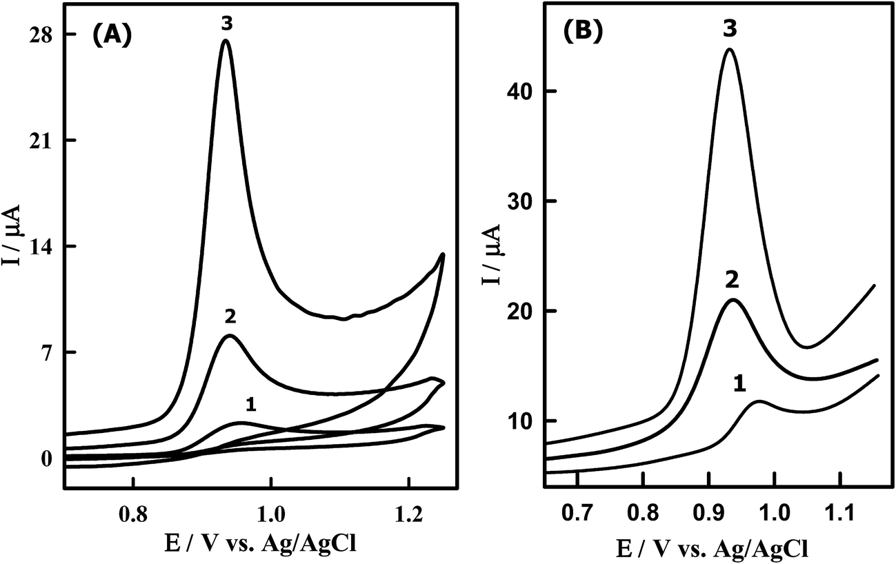
Fig. 4A shows the CVs obtained for 8.50 μM DTIC at bare GCPE (curve 1), undoped CeO2NPs/GCPE (curve 2) and Sn–CeO2NPs/GCPE (curve 3) in PBS (pH 4.0). According to cyclic voltammograms in Fig. 4A, no cathodic peak was observed on the reverse scan within the investigated potential range (0.0–1.2 V) because its oxidation is an electrochemically irreversible process. In this context DTIC underwent a two-electron irreversible oxidation process in aqueous media.11 Compared to those obtained at the bare GCPE (2.33 μA), undoped CeO2NPs/GCPE (7.01 μA), a fairly larger peak current was obtained at the Sn–CeO2NPs/GCPE (24.12 μA). This result suggested that the electron transfer reaction at the Sn–CeO2NPs/GCPE is more facile than that at the bare GCPE and undoped CeO2NPs/GCPE. The electrocatalytic activity of the modified electrode could be ascribed to the presence of nano-Sn–CeO2 which enhanced the conductivity, surface area and facilitated the electron transfer between the biomolecules and the electrode surface.
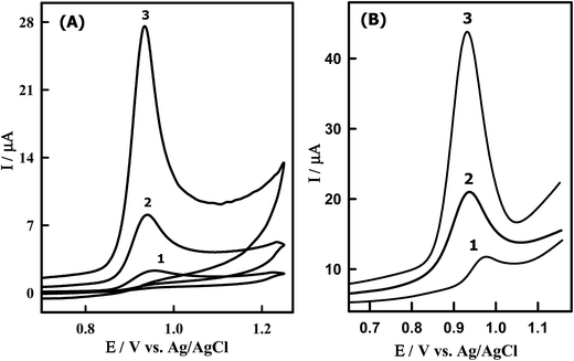 |
| | Fig. 4 (A) CVs of 8.50 μM DTIC in PBS of pH 4.0 obtained at (1) bare GCPE, (2) CeO2NPs/GCPE and (3) Sn–CeO2NPs/GCPE; scan rate, 0.10 V s−1. (B) SW voltammograms of 1.14 μM DTIC in PBS buffer of pH 4.0 obtained at (1) unmodified (2) modified CeO2NPs/GCPE and (3) Sn–CeO2NPs/GCPE; accumulation potential, 0.0 V; accumulation time, 10 s; scan increment, 6 mV; frequency, 120 Hz and pulse height, 35 mVpp. | |
Furthermore, the SWV was performed to obtain better sensitivity because enhanced analytical signals can be achieved by eliminating the non-faradic currents that occur with CV. As can be seen DTIC showed a sharp peak at 932 mV in PBS (pH 4.0) at the Sn–CeO2NPs/GCPE, which corresponds to the oxidation of DTIC (Fig. 4B). The peak current was 45 μA, much larger than that obtained by CV. There is also an enhanced peak current of DTIC at the Sn–CeO2NPs/GCPE (Fig. 4B, curve 3) as compared to a bare GCPE (Fig. 4B, curve 1) and undoped CeO2NPs/GCPE (Fig. 4B, curve 2). The results indicated that the nano-Sn–CeO2 incorporated GCPE had great enhancement peak current of DTIC, which was due to the excellent characteristics of nano-Sn–CeO2 such as high chemical stability, high surface area, good electrical conductivity and high optical transparence. So the electron transfer of DTIC on the Sn–CeO2NPs/GCPE was greatly enhanced without using electron transfer mediator. It is clear that the increase in oxidation current at the proposed modified electrode can offer a special approach for sensitive electrochemical determination of DTIC in biological fluids.
3.5. Effect of potential scan rate
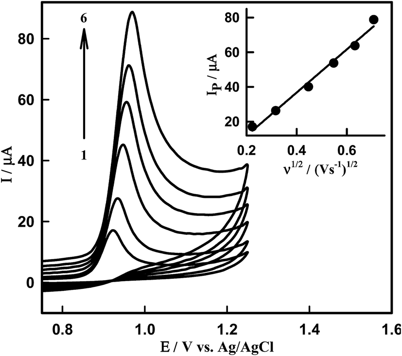
The effect of the scan rate on the oxidation peak current and potential was studied in order to estimate the nature of the electrode process occurring at the Sn–CeO2NPs/GCPE surface. Fig. 5 presents the cyclic voltammograms of DTIC recorded in PBS of pH 4.0 with scan rate varying from 50 to 500 mV s−1. The oxidation peak heights were found to increase linearly with scan rate from 50 to 500 mV s−1. The IP is linearly increased with the square root of scan rate, ν1/2, in the range of 50–500 mV s−1 (inset of Fig. 5). This indicates that the oxidation process of DTIC in PB solution (pH 4.0) on the nano-Sn–CeO2 is a diffusion-controlled process. The effect of the potential scan rate on the peak current may be expressed as log(Ipa) vs. log(ν), which has a slope of 1.0 for the species confined to the electrode surface, or 0.5 for the diffusion controlled system. The dependence of log(Ipa) vs. log(ν) can be expressed by the equation: logIP (μA) = 0.65logν (mV s−1) + 0.11 (R2 = 0.9977) (Fig. S2†). The value of the slope confirms that the process is diffusion-controlled.
 |
| | Fig. 5 CVs of 8.50 μM DTIC on surface of Sn–CeO2NPs/GCPE at various scan rates; (1) 50, (2) 100, (3) 200, (4) 300, (5) 400 and (6) 500 mV s−1 in PBS of pH 4.0. Inset: dependence of peak current on square root of scan rate. | |
Moreover, the peak potential shifted to more positive values on increasing the scan rate, which confirms the irreversibility of the oxidation process, and a linear relationship between EP and logν in the range from 50 to 500 mV s−1 (Fig. S3†) which can be expressed as: EP (V) = 0.04logν (V s−1) + 0.97 (R2 = 0.993).
According to the Laviron theory for an adsorption controlled and totally irreversible electrode process,36 EP is defined by the following equation.
| | |
EP = E° − (2.3RT/αnF)[log(RTks/αnF) − logν]
| (1) |
where
α is the transfer coefficient,
ks is the heterogeneous electron transfer rate constant,
n is the number of electrons transferred,
ν is the scan rate, and
E° is the formal redox potential. Other symbols have their usual meanings. Thus value of
αn can be easily calculated from the slope of
EP vs. log
ν. In this system, the slope was found to be 0.024 taking
T = 298 K,
R = 8.314 J K
−1 mol
−1, and
F = 96480 C mol
−1, the
αn was calculated to be 1.069. The value of
α can be calculated as:
| | |
EP − EP/2 = (47.7/α) mV
| (2) |
where
EP/2 is the potential when the current is at half the peak value. From this, we obtained the value of
α to be 0.54 for Sn–CeO
2NPs/GCPE. So, the number of electrons (
n) transferred in the electrooxidation of DTIC was calculated to be 1.979 ≈ 2 that value is in good agreement with the value reported in the literature.
11 The value of
ks can be determined from the intercept of the previous plot if the value of
αn and
E° are known. The value of
E° can be obtained from the intercept of
EP vs. ν curve by extrapolating to the vertical axis at
ν = 0 V s
−1. Thus, using this information and
eqn (1) the
ks values obtained were 0.782 and 2.356 s
−1 for bare and modified electrodes, respectively. These results may be attributed to the good electrical conductivity as well as the increase of the electrode surface area in the presence of Sn doped CeO
2 nanoparticles and suggested that electron transfer process between the DTIC molecules and Sn–CeO
2NPs/GCPE was very fast.
The surface concentration (Γ, mol cm−2) of electroactive DTIC on the modified electrode Sn–CeO2NPs/GCPE and bar GCPE can be calculated from the slope of the plot of Ipa versus scan rate by:37 IP = n2F2νAΓ/4RT where n is the number of electrons transferred, F (C mol−1) is the Faraday's constant, A (cm2) is the area of the electrode, Γ is the surface concentration of the electroactive substance, DTIC, and ν (V s−1) is the scan rate. The surface concentration (Γ) of DTIC on the Sn–CeO2NPs/GCPE was estimated to be 6.25 × 10⁻¹⁰ mol cm−2, which was larger than 6.04 × 10⁻¹¹ mol cm−2 on GCPE. These values imply that the presence of Sn–CeO2 increases the surface area of the electrode, which in turn increases the Γ of DTIC.
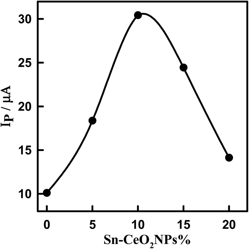
3.6. Optimization of the amount of modifier (5% Sn–CeO2NPs)
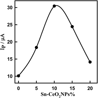
The effect of the amount of 5% Sn–CeO2NPs within the glassy carbon paste electrode on the voltammetric response was evaluated by changing mass ratio of Sn–CeO2NPs to glassy carbon microspheres in the glassy carbon paste (Fig. S4†). The oxidation peak current of DTIC increases with the increasing of amount of modifier because the concentration of Sn–CeO2NPs on the surface of the modified electrode increases correspondingly (Fig. 6). However, when the amount of nano-Sn–CeO2 reaches 10% (w/w) (nano-Sn–CeO2/glassy carbon paste), the peak current reaches its maximum. After this point, any continuing increase in the amount of modifier causes a decrease in the peak current, due to the decrease of the conductivity of the modified electrode. Thus electrode composition of 10% (w/w) nano-Sn–CeO2, 75% (w/w) glassy carbon microspheres and 15% (w/w) paraffin oil was used for further experiments.
 |
| | Fig. 6 Plot of peak current of 1.14 μM DTIC in PBS, pH 4.0 using SWV versus the percentage of 5% Sn–CeO2NPs in the paste. | |
3.7. Optimization of pH
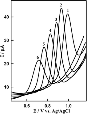
The effect of pH on the SWV responses of DTIC on Sn–CeO2/GCPE was investigated in the pH range from 3 to 8.0 (Fig. 7). It can be clearly observed that the peak current and potential towards the oxidation of DTIC are closely related to the pH value of the supporting electrolyte. It was found that the oxidation peak potential of DTIC shifted toward less positive potential values with increase in the pH (Fig. S5†). This suggests the involvement of protons in the oxidation process. Based on the results obtained, over the studied pH range, a linear relationship was obtained between EP and pH (Fig. S5†), which can be expressed by the following equation: EP (V) = 1015 − 0.057 pH (R2 = 0.999). A comparison between the obtained slope of −0.057 V pH−1 and the theoretical slope of −0.059m/n V pH−1 (m and n being the numbers of protons and electrons, respectively) confirms that equal numbers of protons and electrons participate in the oxidation procedure. According to the overall electrode reaction,11 two electrons and two protons were involved in the DCIT oxidation. The height of the peak reached a maximum and the shape of the curve is better in PBS at pH 4.0 (pKa = 4.42)38 than other buffers. This supporting electrolyte was chosen with respect to sharp response and better peak shape for the construction of calibration curve and for determination of DTIC in standard solution and in biological samples.
 |
| | Fig. 7 SW voltammograms of 1.14 μM DTIC on the surface of Sn–CeO2NPs/GCPE at different pH values (PBS): (1) pH 3.0, (2) pH 4.0, (3) pH 5.0, (4) 6.0, (5) 7.0 and (6) 8.0. Other conditions are the same in Fig. 4B. | |
3.8. Square-wave pulse parameters
The optimum conditions for the SWV were recognized by measuring the current dependence on the instrumental parameters counting pulse height, frequency and scan increment. SW voltammograms of 1.14 μM DTIC in PBS of pH 4.0 onto the Sn–CeO2NPs/GCPE were recorded at various pulse parameters (frequency; f = 20–120 Hz, scan increment; ΔEs = 2–10 mV and pulse height; ΔEa = 20–80 mV). The better developed voltammetric peak was obtained under the following pulse parameters: f = 120 Hz, ΔEs = 6 mV and ΔEa = 35 mVpp using Sn–CeO2NPs/GCPE. These parameters reflect SWVs of high sensitivity and best peak morphology.
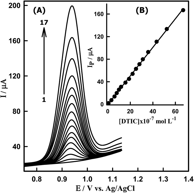
3.9. Square wave voltammetric determination of DTIC concentration
Under optimum conditions, square wave voltammograms are recorded at the Sn–CeO2NPs/GCPE to determine the limit detection (LOD) of DTIC. Fig. 8A shows the typical SWV of different concentrations of DTIC at the modified electrode. It was found that the anodic peak current increased linearly with increasing the concentration of DTIC (Fig. 8B). A linear dynamic range of 6.40 × 10⁻⁸ to 6.69 × 10⁻⁶ M DTIC was obtained following its concentration onto the modified electrode by adsorption accumulation for 10 s at 0.0 V. The analytical results are summarized in Table 2. In this context the sensitivity of the proposed sensor was found to be of 361.43 μA μM−1 cm−2. The LOD was calculated using the relation kSDa/b, where k = 3, SDa is the standard deviation of the intercept and b is the slope of the calibration plot. The LOD value was found to be 3.79 × 10⁻⁹ M DTIC (0.690 ng mL−1), which confirmed good sensitivity of the proposed sensor. This concentration detection limit of DTIC (3.79 × 10⁻⁹ M) is very low in compared with the values reported by other reported methods.6,11 This wide linear range and low detection limit can be attributed to the effect of the Sn–CeO2NPs, which provides a large specific area to increase the loading amount of DTIC. Meanwhile, the electron transfer to the electrode surface can be accelerated and the electrochemical signal is amplified due to the outstanding electric conductivity of the Sn–CeO2NPs/GCPE. Thus, the proposed method could be effectively used for the determination of DTIC in commercial samples.
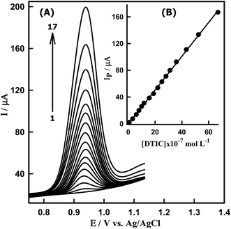 |
| | Fig. 8 (A) SW voltammograms of DTIC at Sn–CeO2NPs/GCPE in PBS at pH 4.0. [DTIC]: (1) blank, (2) 0.064, (3) 0.32, (4) 0.60, (5) 0.79, (6) 0.99, (7) 1.18, (8) 1.57, (9) 1.88, (10) 2.21, (11) 2.51, (12) 2.81, (13) 3.12, (14) 3.59, (15) 4.33, (16) 5.24 and (17) 6.69 μM. (B) Calibration plot of IP (μA) versus [DTIC] in PBS of pH 4.0. | |
Table 2 Regression data of the calibration lines for quantitative determination of DTIC in standard solution, serum sample and urine sample in PBS (pH 4.0) at Sn–CeO2NPs/GCPE using SWV
| Parameters |
Standard solution |
Serum sample |
Urine sample |
| Measured potential (V) |
0.934 |
0.933 |
0.935 |
| Linearity range (μM) |
0.064–6.69 |
0.076–6.59 |
0.069–5.31 |
| Slope (μA M−1) |
2.53 × 10⁷ |
1.39 × 10⁷ |
1.62 × 10⁷ |
| SE of slope |
7.53 × 10⁴ |
9.27 × 10⁴ |
7.14 × 10⁴ |
| Intercept (μA) |
−0.31 |
0.99 |
1.34 |
| SE of intercept |
5.10 × 10⁻³ |
9.25 × 10⁻³ |
7.48 × 10⁻³ |
| Determination coefficient (R2) |
0.9991 |
0.9989 |
0.9983 |
| Number of measurements (n) |
5 |
5 |
5 |
| LOD (M) |
3.79 × 10⁻⁹ |
6.04 × 10⁻⁹ |
6.29 × 10⁻⁹ |
| Sensitivity (μA μM−1 cm−2) |
361.43 |
198.57 |
231.43 |
| Repeatability of peak current (RSD%) |
1.32 for 3.2 × 10⁻⁷ |
2.18 for 3.12 × 10⁻⁷ |
1.46 for 3.23 × 10⁻⁷ |
| Reproducibility of peak current (RSD%) |
1.63 for 3.2 × 10⁻⁷ |
2.32 for 3.12 × 10⁻⁷ |
1.79 for 3.23 × 10⁻⁷ |
3.10. Interference studies
In order to evaluate the selectivity of the proposed method for the determination of DTIC, the influence of potentially interfering substances on the determination of this compound was investigated using SWV at the Sn–CeO2NPs/GCPE. The tolerance limit for interfering species was considered as the maximum concentration of foreign species that caused a relative error less than ±5% for determination of 1.18 μM DTIC under the optimized conditions. For 1.18 μM of DTIC, the result showed that over 200 fold excess of ascorbic acid, uric acid, alanine, cysteine, glucose, citric acid, uracil and serine did not interfere with DTIC response (Table S1†). The results obtained show recoveries in the range from 97.88 to 102.17 for 1.18 μM of DTIC solution, indicating that there were no important matrix interferences for the samples by the proposed SWV method using Sn–CeO2NPs/GCPE. From these results, it may be concluded that the method is free from interference by most coexisting substances and shows promising properties for use in real samples.
3.11. Stability and reproducibility of the electrode
The Sn–CeO2NPs/GCPE was stable, even after 45 days if it preserved in a closed container. Daily recording the SWV of 3.2 × 10⁻⁷ M of DTIC checked the stability of the proposed modified electrode; the electrode retained 98.55% of its initial peak current response with a standard deviation of 1.32%. This shows the long-term stability of the Sn–CeO2NPs/GCPE.
In order to evaluate the accuracy and precision of the proposed method the analysis of DTIC at three levels of low, moderate and high concentrations of the calibration curve was carried out in five independent series at the same day (intra-day) and performed at same levels on five different days (inter-day). The results obtained for intra-day and inter-day precision and accuracy are presented in Table 3. As can be seen, the RSD values of the measurements were not greater than 1.80% and 2.75% for intra-day and inter-day determinations, respectively, and the accuracy of determination was not different from added values by more than 3.33%. Also the recovery of DTIC was found to be between 96.67% and 101.69%. These results confirm the good precision and accuracy of the proposed method. This indicates that the Sn–CeO2NPs/GCPE has a good repeatability.
Table 3 Precision (intra and inter day) and accuracy for assay of DTIC (n = 5)
| Added (μM) |
Found (μM) |
Precision RSD% |
Relative error% |
Recovery% |
| Intra-day |
| 0.60 |
0.61 ± 0.011 |
1.80 |
−1.66 |
101.66 |
| 1.18 |
1.16 ± 0.013 |
1.12 |
1.69 |
98.31 |
| 5.24 |
5.22 ± 0.027 |
0.52 |
0.38 |
99.62 |
|
| Inter-day |
| 0.60 |
0.58 ± 0.016 |
2.75 |
3.33 |
96.67 |
| 1.18 |
1.20 ± 0.022 |
1.83 |
−1.69 |
101.69 |
| 5.24 |
5.17 ± 0.096 |
1.86 |
1.33 |
98.66 |
3.12. Applications of the Sn–CeO2NPs/GCPE in real sample analysis
The analysis of DTIC in real samples is crucial for clinical applications using the proposed sensor probe. The practical applicability of the optimized sensor was successfully applied to the quantification of DTIC in a number of real samples such as human serum, human urine (Fig. S6 and S7†) and pharmaceutical vial (Fig. S8†). For this purpose, the real samples were prepared as described in the Experimental section (Section 2). To check the accuracy of the procedure, the samples were spiked with known and different amounts of DTIC. The aliquots of these prepared samples were analyzed in five times (n = 5) according to the recommended procedures. A linear dynamic range of 7.60 × 10⁻⁸ to 6.59 × 10⁻⁶ M DTIC (for serum sample) and of 6.90 × 10⁻⁸ to 5.31 × 10⁻⁶ M DTIC (for urine sample) were obtained and the analytical results are tabulated in Table 2. The recoveries in serum and urine samples were found to lie in the range from 96.77% to 103.12% (Table S2†). The results obtained suggest that the proposed voltammetric sensor based on the Sn–CeO2NPs/GCPE is reliable and free from the matrix interferences in the analysis of human serum and urine samples.
The practical analytical utility of the Sn–CeO2NPs/GCPE was also illustrated by the determination of DTIC in pharmaceutical products (Fig. S8†). The standard addition method was applied in this analysis, and the results are listed in Table S3.† The recovery of the spiked samples ranged between 98.00% and 100.40%, indicating that the fabricated sensor could be efficiently used for the determination of DTIC in pharmaceutical samples.
4. Conclusions
In this work, Sn doped CeO2 nanoparticles were successfully synthesized and further employed to fabricate Sn–CeO2NPs/GCPE for the first time. Characterization data of synthesized Sn–CeO2NPs by XRD, EDX and TEM confirmed that the Sn replaces Ce site and that the crystal structure of CeO2 was retained as rutile phase up to the maximum loading of 5 wt% Sn. The fabricated electrode was successfully used to study the electrochemical behavior of DTIC. The Sn–CeO2NPs/GCPE exhibited an excellent electrocatalytic activity towards the oxidation of DTIC. The Sn–CeO2NPs/GCPE offers a good, reliable and simple method for the selective determination of DTIC in phosphate buffer solution of pH 4.0. The Sn–CeO2NPs/GCPE not only shifted the oxidation potential of DTIC towards less positive potential but also enhanced its oxidation current when compared to undoped CeO2 modified and bare GC electrodes. The fabricated electrochemical sensor exhibits good selectivity, a wide linear range, lower detection limit, high sensitivity, storage stability and acceptable reproducibility. In addition, the Sn–CeO2NPs/GCPE was demonstrated to be useful for the detection of DTIC in pharmaceutical and human biological samples with good accuracy and precision. All these advantageous features make the proposed Sn–CeO2NPs/GCPE sensor successfully applied for the determination of DTIC in the clinical samples, which can be used to diagnose the health condition of patients.
Live subject statement
All experiments were performed in compliance with the relevant laws and Assiut University's guidelines. The analysis of DTIC in real samples such as human serum, human urine were approved by the ethics committees of Assiut Medical University – Joint Institutional Review Board. All of the subjects signed an informed consent form before examination.
References
- M. M. Eggermont and J. M. Kirkwood, Re-evaluating the role of dacarbazine in metastatic melanoma: what have we learned in 30 years?, Eur. J. Cancer, 2004, 40, 1825–1836 CrossRef PubMed.
- M. Spasova and E. Golovinski, Pharmacobiochemistry of arylalkyltriazenes and their application in cancer chemotherapy, Pharmacol. Ther., 1985, 27, 333–352 CrossRef CAS.
- X. Wang, Y. Li, S. Gong and D. Fu, A spectroscopic study on the DNA binding behavior of the anticancer drug dacarbazine, Spectrosc. Lett., 2002, 35, 751–756 CrossRef CAS.
- M. Sanada, M. Hidaka, Y. Takagi, T. Y. Takano, Y. Nakatsu, T. Tsuzuki and M. Sekiguchi, Modes of actions of two types of anti-neoplastic drugs, dacarbazine and ACNU, to induce apoptosis, Carcinogenesis, 2007, 28, 2657–2663 CrossRef CAS PubMed.
- D. T. King and J. T. Stewart, HPLC determination of dacarbazine, doxorubicin, and ondansetron mixture in 5% dextrose injection on underivatized silica with an aqueous-organic mobile phase, J. Liq. Chromatogr., 1993, 16, 2309–2323 CrossRef CAS.
- D. Fiore, A. J. Jackson, M. S. Didolkar and V. R. Dandu, Simultaneous determination of dacarbazine, its photolytic degradation product, 2-azahypoxanthine, and the metabolite 5-aminoimidazole-4-carboxamide in plasma and urine by high-pressure liquid chromatography, Antimicrob. Agents Chemother., 1985, 27, 977–979 CrossRef CAS PubMed.
- A. Haque and J. T. Stewart, Isocratic determination of dacarbazine and related impurities 2-azahypoxanthine and 5-amino-imidazole-4-carboxamide by HPLC on an avidin protein column, J. Liq. Chromatogr. Relat. Technol., 1999, 22, 933–943 CrossRef CAS.
- Y. Liu, W. Zhang and Y. Yang, Validated hydrophilic interaction LC-MS/MS method for simultaneous quantification of dacarbazine and 5-amino-4-imidazole-carboxamide in human plasma, Talanta, 2008, 77, 412–421 CrossRef CAS PubMed.
- A. J. Ordieres, A. C. Garcia, P. T. Blanco and W. F. Smyth, An electroanalytical study of the anticancer drug dacarbazine, Anal. Chim. Acta, 1987, 202, 141–149 CrossRef CAS.
- M. Song, R. Zhang and X. Wang, Nano-titanium dioxide enhanced biosensing of the interaction of dacarbazine with DNA and DNA bases, Mater. Lett., 2006, 60, 2143–2147 CrossRef CAS.
- J. R. Barreira, A. Costa, A. J. Miranda and P. Tunon, Electrochemical oxidation of dacarbazine and its major metabolite (AIC) on carbon electrodes, Electroanalysis, 1989, 1, 529–534 CrossRef.
- M. U. Ahmed, M. M. Hossain and E. Tamiya, Electrochemical biosensors for medical and food applications, Electroanalysis, 2008, 20, 616–626 CrossRef CAS.
- Y. Xiao and C. M. Li, Nanocomposites: From fabrications to electrochemical bioapplications, Electroanalysis, 2008, 20, 648–662 CrossRef CAS.
- N. Golego, S. A. Studenikin and M. Cocivera, Sensor photoresponse of thin-film oxides of zinc and titanium to oxygen gas, J. Electrochem. Soc., 2000, 147, 1592–1594 CrossRef CAS.
- X. Wang, J. Song, J. Liu and Z. L. Wang, Direct-Current Nanogenerator Driven by Ultrasonic Waves, Science, 2007, 316, 102–105 CrossRef CAS PubMed.
- K. Keren, R. S. Berman, E. Buchstab, U. Sivan and E. Braun, DNA-templated carbon nanotube field-effect transistor, Science, 2003, 302, 1380–1382 CrossRef CAS PubMed.
- H. K. Maleh, S. Rostami, V.-K. Gupta and M. Fouladgar, Evaluation of ZnO nanoparticle ionic liquid composite as a voltammetric sensing of isoprenaline in the presence of aspirin for liquid phase determination, J. Mol. Liq., 2015, 201, 102–107 CrossRef.
- M. Baghayeri, E.-N. Zare and M.-M. Lakouraj, A simple hydrogen peroxide biosensor based on a novel electro-magnetic poly(p-phenylenediamine) and Fe3O4 nanocomposite, Biosens. Bioelectron., 2014, 55, 259–265 CrossRef CAS PubMed.
- S. Das and V. Jayaraman, SnO2: A comprehensive review on structures and gas sensors, Prog. Mater. Sci., 2014, 66, 112–255 CrossRef CAS.
- M. Ibrahim, Y. Temerk, H. Ibrahim and M. Kotb, Indium
oxide nanoparticles modified carbon paste electrode for sensitive voltammetric determination of aromatase inhibitor formestane, Sens. Actuators, B, 2015, 209, 630–638 CrossRef CAS.
- N. Lavanya, S. Radhakrishnan and C. Sekar, Fabrication of hydrogen peroxide biosensor based on Ni doped SnO2 nanoparticles, Biosens. Bioelectron., 2012, 36, 41–47 CrossRef CAS PubMed.
- N. Lavanya, S. Radhakrishnan, C. Sekar, M. Navaneethan and Y. Hayakawa, Fabrication of Cr doped SnO2 nanoparticles based sensor for the selective determination of riboflavin in pharmaceuticals, Analyst, 2013, 138, 2061–2067 RSC.
- N. Lavanya, S. Radhakrishnan, N. Sudhan, C. Sekar, S. Leonardi, C. Cannilla and G. Neri, Fabrication of folic acid sensor based on the Cu doped SnO2 nanoparticles modified glassy carbon electrode, Nanotechnology, 2014, 25, 295501 CrossRef CAS PubMed.
- S. D. Bukkitgar, N. P. Shetti, R. M. Kulkarni and M. R. Doddamani, Electro-oxidation of nimesulide at 5% barium-doped zinc oxide nanoparticle modified glassy carbon electrode, J. Electroanal. Chem., 2016, 762, 37–42 CrossRef CAS.
- N. Lavanya, C. Sekar, S. Ficarra, E. Tellone, A. Bonavita, S. G. Leonardi and G. Neri, A novel disposable electrochemical sensor for determination of carbamazepine based on Fe doped SnO2 nanoparticles modified screen-printed carbon electrode, Mater. Sci. Eng., C, 2016, 62, 53–60 CrossRef CAS PubMed.
- N. Lavanya, E. Fazio, F. Neri, A. Bonavita, S. G. Leonardi, G. Neri and C. Sekar, Electrochemical sensor for simultaneous determination of ascorbic acid, uric acid and folic acid based on Mn–SnO2 nanoparticles modified glassy carbon electrode, J. Electroanal. Chem., 2016, 770, 23–32 CrossRef CAS.
- E. R. Brown and R. F. Large, in Physical Methods of Chemistry, ed. A. Weissberger and B. W. Rossiter, Wiley Inter science, Rochester New York, 1964, p. 423 Search PubMed.
- E. Aneggi, D. Wiater, C. de Leitenburg, J. Llorca and A. Trovarelli, Shape-dependent activity of ceria in soot combustion, ACS Catal., 2014, 4, 172–181 CrossRef CAS.
- J. Li, Z. Zhang, Z. Tian, X. Zhou, Z. Zheng, Y. Ma and Y. Qu, Low pressure induced porous nanorods of ceria with high reducibility and large oxygen storage capacity: synthesis and catalytic applications, J. Mater. Chem. A, 2014, 2, 16459–16466 CAS.
- R. Rao, M. Yang, C. Li, H. Dong, S. Fanga and A. Zhang, A facile synthesis for hierarchical porous CeO2 nanobundles and their superior catalytic performance for CO oxidation, J. Mater. Chem. A, 2015, 3, 782–788 CAS.
- A. B. Kehoe, D. O. Scanlon and G. W. Watson, Role of lattice distortions in the oxygen storage capacity of divalently doped CeO2, Chem. Mater., 2011, 23, 4464–4468 CrossRef CAS.
- Y. Temerk and H. Ibrahim, A new sensor based on In doped CeO2 nanoparticles modified glassy carbon paste electrode for sensitive determination of uric acid in biological fluids, Sens. Actuators, B, 2016, 224, 868–877 CrossRef CAS.
- H. Ibrahim and Y. Temerk, A novel electrochemical sensor based on B doped CeO2 nanocubes modified glassy carbon microspheres paste electrode for individual and simultaneous determination of xanthine and hypoxanthine, Sens. Actuators, B, 2016, 232, 125–137 CrossRef CAS.
- Y. Wu and C. Lin, The microstructures and property analysis of aliovalent cations (Sm3+, Mg2+, Ca2+, Sr2+, Ba2+) co-doped ceria-base electrolytes after an aging treatment, Int. J. Hydrogen Energy, 2014, 39, 7988–8001 CrossRef CAS.
- R. N. Goyal, V. K. Gupta and S. Chatterjee, Voltammetric biosensors for the determination of paracetamol at carbon nanotube modified pyrolytic graphite electrode, Sens. Actuators, B, 2010, 149, 252–258 CrossRef CAS.
- E. Laviron, General expression of the linear potential sweep voltammogram in the case of diffusionless electrochemical systems, J. Electroanal. Chem., 1979, 101, 19–28 CrossRef CAS.
- E. Laviron, The use of linear potential sweep voltammetry and of a.c. voltammetry for the study of the surface electrochemical reaction of strongly adsorbed systems and of redox modified electrodes, J. Electroanal. Chem., 1979, 100, 263–270 CrossRef CAS.
- J. Sangster, Log Kow Databank A, Databank of Evaluated Octanol–Water Partition Coefficients (logP) on Microcomputer Diskette, Sangster Res Lab, 1993 Search PubMed.
Footnote |
| † Electronic supplementary information (ESI) available. See DOI: 10.1039/c7ra04331g |
|
| This journal is © The Royal Society of Chemistry 2017 |
Click here to see how this site uses Cookies. View our privacy policy here. 
 Open Access Article
 This Open Access Article is licensed under a
  *,
Yassien Temerk and
Hossieny Ibrahim
*,
Yassien Temerk and
Hossieny Ibrahim