DOI:
10.1039/C7RA03922K
(Paper)
RSC Adv., 2017,
7, 34939-34944
Highly compressible graphene/polyurethane sponge with linear and dynamic piezoresistive behavior
Received
6th April 2017
, Accepted 28th June 2017
First published on 12th July 2017
Abstract
A high-elastic graphene/polyurethane (PU) nanocomposite with excellent electromechanical properties was fabricated by a facile ice-templated assembly strategy. The resulting PU-reinforced graphene sponges (PGS) not only possess a combination of low density (18 ± 5 mg cm−3) and adjustable sensitivity (0.75 to 3.08 kPa−1) but can also withstand large strain without permanent deformation. The pressure-sensitive sensors based on our sponge exhibit a negative piezoresistive effect, and the resistance can change from 5 kΩ to 25 Ω under 99% strain. We have also designed a novel device to investigate the delay ratio and fast piezoresistive response with different loading frequencies. Owing to its rapid response (14 ms), high flexibility and facile fabrication, this graphene strain sensor presents great potential for cost-effective artificial skins, which are urgently needed in soft robotic systems. Moreover, this effective assembly strategy provides a route to fabricating novel functional materials by embedding porous graphene inside another porosint.
1 Introduction
Assembling three-dimensional (3D) porous monoliths from graphene, whilst keeping the intrinsic advantages of the graphene nanosheet building blocks, has great promise for practical applications.1,2 Most cellular graphene bulk materials such as graphene aerogels (GAs), are approaching this nano-architectonic idea due to their remarkable electrical conductivity, large surface area, and high porosity.3–5 However in most cases the collapse of the pore structure results in irreversible structural failure of the formed GAs and is unfavorable for the preparation of robust and scalable macroscopic materials.6 Although some elastic GAs are strong under compressive stress, the initial thickness of the samples decreases as the number of compression cycles increases.7 Accordingly, in recent years graphene/polymer nanocomposites have attracted intensive attention because of the prominent advantages they present over conventional carbon porous material.8–10 For example, Hu et al.10 prepared a graphene/polymer hybrid aerogel by immersing GAs in organic solvents with poly(dimethylsiloxane) (PDMS) monomer and curing agent. After evaporation and curing steps the formed aerogel exhibited high compressibility and conductivity. As the most versatile polymer reinforcement, polyurethane sponge (PUS) has been widely used to introduce cellular structures into piezoresistive sensors.3,11–13 These interconnected sponge networks are regarded as the most efficient strategy to increase sensitivity and deformability in wearable piezoresistive sensors.14 Moreover, some explorations of cellular piezoresistive sensors are directly motivated by the possibility of controlling pore morphology and designing patterned arrays for devices. Yao et al.3 designed a fractured microstructure graphene sponge which has high sensitivity in low pressure regions and high cycling stability for artificial skin. Liu et al.15 prepared a highly compressible graphene sponge with an interconnected cell structure and a stable pressure-sensing signal by directly freeze-drying graphene organic solvents with the addition of thermoplastic polyurethane pellets. Actually, various approaches for forming graphene-based sponges by solvent dispersion and dip-coating methods can be found in the literature in which the formation of ordered 3D porous structures comes from the addition of a polymer skeleton. As for graphene-based piezoresistive sensors, graphene cellular structures enable a recyclable, synchronous, and fast piezoresistive response more easily than the existing polymer-based porous structures. Liu et al.16 developed a highly compressible GA with a 3D porous structure by an ice-templated method, and the electrical resistance of the aerogel was strongly dependent on the strain variation from 0 to 83.7%. The use of graphene in foam-like nanocomposites allows the high strain rate deformation to make elastomeric pressure/strain sensors. However, the piezoresistive effects of such graphene sponges are not very well-understood, and more details, such as the frequency response of the sensors, need to be studied to better understand how these nanocomposites can serve reliably as functional sensor materials. Qiu et al.17 reported a piezoresistive graphene-based cellular elastomer with exceptional dynamic capabilities, which was prepared by pre-freezing of a GO precursor with further reduction processing. Accordingly, introducing a GA porous structure into the targeted polymer matrices provided an effective strategy for preparing the graphene sponge monolith for novel applications.
In this work, we have developed conductive graphene sponges via assembly of the cellular graphene structure into the PUS open-cell network. The facile preparation process without using organic solvent can be finished in 12 h via an ice-templating method to form a highly porous structure. The hierarchical porous structure of PGS resulted in excellent electromechanical properties and the resistance could change from 5 kΩ to 25 Ω under 99% strain. Additionally, the broad piezoresistive relationship between the direct ratio of compression versus the resistance verified the uniform graphene cellular walls in the microstructure. We also designed a novel test to investigate the piezoresistive response under different frequencies. The low delay time (14 ms) of the dynamic forces which covered a medium-pressure region (1–70 kPa) represents a great potential for artificial skin.
2 Experimental
2.1 Fabrication of PGS
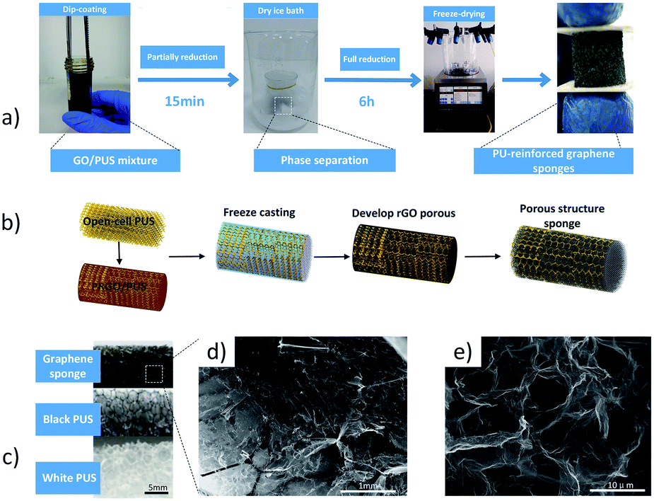
First graphite oxide was synthesized according to a modified Hummers method,18,19 and a graphene oxide (GO) suspension with a concentration of 3 mg ml−1 was mixed with ascorbic acid powder in a beaker. Commercial polyurethane sponges (PUS) were cut into a cylindrical sample and then immersed in the as-prepared solvent in a test tube for dip-coating. The beaker was placed in a boiling water bath for 15 min and a freeze casting process was carried out immediately after with the beaker partially submerged in a dry ice bath for 6 h. The hydrothermal reduction process led to an increase in the hydrophobicity of the partly reduced graphene oxide (PRGO) sheets, which gradually shrunk into the open-framework of the PUS to form a compact gel-like compound floating in the transparent liquid. As the reduction proceeded, the evidence suggested the removal of oxygen-containing groups including the mixture with different colors and floating in the transparent liquid.16 Then, the compact gel-like compound was preformed by being directionally frozen from the beaker/refrigerant interface to the top surface. The PRGO layers trapped between neighboring PUS skeletons were repelled from the forming ice crystals to induce a continuous network. Thereafter the beaker was placed in a vacuum-freezing dryer to draw off the ice crystals (by sublimation) for an additional 12 h until it was totally dry, resulting in the formation of a hierarchical porous structure as shown in Fig. 1d and e.
 |
| | Fig. 1 (a) A schematic representation of the fabrication process of the graphene sponge, (b) a schematic illustration of an ice-templated assembly strategy to construct a GO/PUS porous structure, the ordered network called the sponge skeleton is marked in yellow dotted lines, (c) comparisons of digital images of commercial sponge and graphene sponge, and (d and e) SEM images of the hierarchical porous structure of PGS at different resolutions. | |
2.2 Characterizations
The microstructure and morphology were observed by an environmental scanning electron microscope (FEI Quanta 200, Netherlands) at 20 kV. The scanning was performed from 5° to 45° at a speed of 0.02° min−1. X-ray diffraction (XRD) measurements were carried out using an X’Pert PRO DY2198 (PANalytical B.V. Netherlands) with CuKα radiation at a generator voltage of 40 kV and a generator current of 40 mA. GO and PGS were characterized with a Nicolet 6700 Fourier transform infrared spectroscopy (FT-IR). The stress–strain curves of PGS were determined by an Instron (Micro Tester, 5858) using a strain control mode with a compressive strain rate of 100% min−1. The electrical conductivity of the samples was measured using a two-point probe method with two copper electrodes. A homemade measuring system (as shown in Fig. 6a) was designed for the purpose of the dynamic test. The device used a Micro Load Cell (Phidgets, CZL616C) to measure the forces being applied to the top surface. The waveforms of the outcome signal were collected by a digital storage oscilloscope (Tektronix, TBS1052B).
3 Results and discussion
3.1 Morphology of PGS
In this work 3D graphene aerogels were used as basic building blocks, and were assembled into the host cellular architecture of PUS. Fig. 1a illustrates the synthesis procedure of a cylindrical sample. Our method for PGS synthesis introduced an ice-templated synthesis method, and the typical freeze-casting process is shown schematically in Fig. 1b. After partial reduction, the blended solution was subsequently frozen to produce a porous structure. When the gel-like compound cooled to below the freezing point, the ice crystals grew and expelled the reduced GO sheets to form a phase separation. One benefit of this low cost wet shaping technique is that various porous structures can be easily obtained by adjusting the precursor concentrations and thermodynamic parameters. Interconnected 3D networks of graphene aerogel formed among the void spaces of the polymer scaffold. The macrographic comparison of commercial sponge also verified the dense structure of PGS as shown in Fig. 1c. After freeze-drying, the ice crystals disappeared and graphene sponge with nested graphene aerogel was thus obtained. As the hierarchical structure aligned to the growth of ice crystals is highly isotropic, the isotropy of the sponge wall is more like a corbelled branch of this nest structure as shown in Fig. 1d. This hierarchical porous structure greatly strengthened the stability of the graphene aerogel network which was formed after freeze-drying. The freezing temperature and the amount of oxygen-containing groups of PRGO have been found to be responsible for the microporous morphologies.20
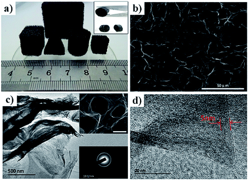
For specific applications the PGS can be easily cut into desired shapes and sizes as shown in Fig. 2a, and is not dependent on varisized reactors. To confirm that the rGO sheets could interpenetrate the sponge, the cylindrical PGS was cut off from the middle position, and it can be clearly seen that the shear plane was also uniformly black, indicating that the rGO sheets permeated the PUS thoroughly. The thus-prepared PGS exhibited a porous structure with a pore size of 10 μm as shown in Fig. 2b. TEM images (Fig. 2c) show how the thin graphene wall folds into a fibrous structure as mentioned in a previously reported work.21 It is beneficial to study these morphological features by adding the sponge skeleton to substantiate structural coherence and the integrity of the generated GA layered assembly, and it is helpful to see how they are related macroscopically. Thus the intercalation of graphene nanosheets exclusively inside the sponge skeleton developed this new multi-layered structure.
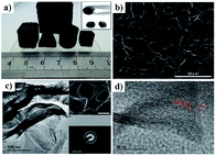 |
| | Fig. 2 (a) Digital images of different shapes of PGS, the inset shows the cut plane view of PGS with a cylindrical morphology. (b) A SEM image of PGS with a porous structure. (c) TEM images of the typical folded graphene walls of PGS. The top inset image exhibits a porous structure with a scale bar of 10 μm. The bottom inset image is the electron diffraction pattern. (d) The thickness of the stacked graphene layers (red arrow) is 5 nm. | |
The structural phases of the obtained GO and PGS were studied by XRD, and the results are shown in Fig. 3a. The diffraction peak at 2θ = 10.8° disappears in the XRD pattern of graphene sponge, indicating that there is no three-dimensional stack of the reduced GO (rGO) sheets. Meanwhile, Fourier transform infrared spectroscopy (FTIR) is a nondestructive tool to characterize the electronic and structural properties of carbonaceous sponges, which was employed to confirm the reduction of GO. Fig. 3b shows the typical FT-IR spectra for GO and PGS. To our knowledge, the peaks that appeared at around 3340, 1726, 1409 and 1217 cm−1 were defined as O–H stretching, stretching vibrations of C![[double bond, length as m-dash]](https://www.rsc.org/images/entities/char_e001.gif) O, CC stretching and C–O stretching respectively. The dramatic decrease of the stretching vibrations of O–H, CO and C–O confirmed that the reduction of the oxygen-containing groups in GO was successful by hydrothermal reduction.
O, CC stretching and C–O stretching respectively. The dramatic decrease of the stretching vibrations of O–H, CO and C–O confirmed that the reduction of the oxygen-containing groups in GO was successful by hydrothermal reduction.
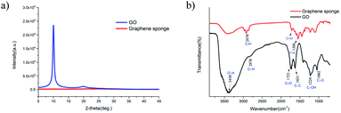 |
| | Fig. 3 (a) XRD patterns and (b) FT-IR spectra of PGS. | |
3.2 Electrical conductivity of graphene sponge
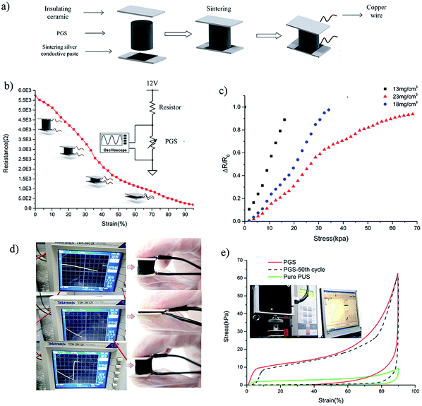
In order to explore the stress-dependent conductivity of the graphene sponge under the axial compression process, we tried to make the sponge into pressure/strain sensors. The PGS cylinder (10 mm in diameter and 12 mm in height) was embedded into two parallel ceramic sheets with conductive silver paste, and two copper wires were connected onto the electrodes (Fig. 4a). Then, it was connected to a common and useful series resistor circuit (voltage divider circuit) containing a metal film resistor and PGS to convert the resistance changes to voltage variations. The output voltage from PGS equals the input voltage scaled by a ratio of resistors, and the PGS as the bottom resistor divided by the sum of the resistors can be calculated as:| |
 | (1) |
where Vi is the input voltage applied to the series circuit, and Vp and Ve are the resistances of the PGS and metal film resistor, respectively. Since the oscilloscope can display a time-varying signal and record a large amount of data within a short period of time, all of the static and dynamic experiments used the same system to make an acquisition so that the results could be correlated. The relationship between the electrical resistance of PGS and the compression strain was also measured (Fig. 4b). The electrical resistance signal was strongly dependent on the deformation and so it varied from 5750 to 25 Ω as the strain varied from 0 to 99%. This was mainly because the cell structure of PGS suffered a higher compressive strain, causing better contact between the graphene sheets and greater electrical conductivity. In the case of the compressible graphene aerogels, the typical resistance versus strain curve in the elastic region could be approximated reasonably well with a linear function (calculated from the long linear part of the curve). This may be due to the linear contraction of the hybrid porous structure when they are stressed as a special conductive network. Besides, the unique electromechanical properties in the linear-elastic region enabled a higher and adjustable sensitivity. As shown in Fig. 4c, the sensitivity of the PGS (sensitivity = δ(ΔR/R0)/δp, where the pressure p was applied) could be tuned gradually from 0.75 kPa−1 (13 mg cm−3) to 3.08 kPa−1 (23 mg cm−3) by changing the concentration of the GO precursor. Meanwhile, the sensitivity was comparable to other strain sensors with complicated microstructure designs (Table 1). Additionally, the stress–strain curves of the PGS under cyclic loads in the axial direction showed excellent resilience when compared with the PUS (Fig. 4e). The compressive stress of PUS is much less than that of PGS, suggesting that the oriented graphene sheets reinforced the elastic stress.
 |
| | Fig. 4 (a) A schematic illustration of the preparation of a pressure sensor using graphene sponge, ceramic sheets and metal wires. (b) The change in electrical resistance of the PGS with increasing strain. (c) The responsivity of PGS (ΔR/R0) as a function of compression stress with different densities (ΔR/R0 = (R0 − R)/R0, where R and R0 denote the resistance with and without applied pressure, respectively). The slope of each curve indicates the sensitivity of each sample to pressure. (d) The real-time signal readout from the oscilloscope when the basic compression/recovery test was performed. The max. strain was operated up to 99% manually. (e) The stress–strain curves of the PGS and PUS during the loading/unloading processes. | |
Table 1 Comparison of different flexible sensor solutions, where ε is the tested strain
| Ref. |
Functional material |
Strain |
Sensitivity |
Delay time |
| 22 |
CNTs/graphite |
20% |
0.6 kPa−1 |
— |
| 23 |
CNTs |
40% |
0.02 kPa−1 |
— |
| 24 |
Graphene paper |
100% |
7.1 (100% ε) |
— |
| 25 |
CNTs/Ag |
— |
0.19 kPa−1 |
200 ms |
| 26 |
CNT/PU |
40% |
0.8 (40% ε) |
— |
| 27 |
Graphene layer |
— |
0.96 kPa−1 |
212 ms |
| 28 |
Photothermally rGO |
— |
19 mV kPa−1 |
1 s |
| 17 |
Graphene aerogel |
10% |
0.23–10 kPa−1 |
0.2 ms |
| PGS |
Graphene sponge |
99% |
0.75–3.08 kPa−1 |
14 ms |
3.3 Dynamic piezoresistive response
The construction of a graphene network in the insulating PU matrix not only effectively enhanced the static piezoresistive behavior of PGS, but it may have also improved the identifiability of the external dynamic pressure. Researchers concluded that the interlayer of graphene sheets under the dynamic deformation would lead to a synchronous change in the electrical resistance, which was inherently hard to obtain from the existing polymer-based elastomers.17 However, few studies and tests have found the low electromechanical hysteresis of viscoelastic graphene–polymer nanocomposites at large oscillatory strain amplitudes to verify the mobility of graphene nanosheets in polymer matrix. In order to explore the dynamic response of graphene bulk materials experimentally, multiple devices such as stepper motors, electromagnetic vibration shakers and other frequency devices have usually been used. For instance, a stepper motor-driven positioner could generate a constant strain at low frequencies (0–13.5 Hz), and a higher frequency can only be operated under small strain (<1%) by using the DMA and electromagnetic shaker.17 For monolith sensors like PGS, a single device can provide a wider frequency range and a larger bulk strain should be used for more meaningful outcomes.
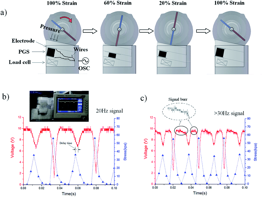
Meanwhile, considering that the dynamic response of soft materials is generally time-dependent as a result of being viscoelastic,29 it is desirable to choose proper test parameters such as different amplitudes, strain rates and waveforms to characterize the dynamic response (Fig. 5). Therefore, we designed a low-cost and energy efficient dynamic test system, in which the amplitude (>50%) and the rate (>30 Hz) of strain were generated by the rotating blade compressing the loose joint fixture on the top of sample. This controllable and repeatable process was executed inside a sealed box and was able to sense both the frequency and amplitude of forces synchronously as shown in Fig. 6a. The symmetry paddle also enabled the PGS to react to two subtle dynamic pressures (input signal) in one cycle. Such capability would be very useful for the design of new tactile sensors that are able to provide essential sensing feedback such as vibration, which are urgently needed for cost-effective wearable electronics. The resulting frequency response as a function of time was consistent with the signal waveforms of periodic pressures at 20 Hz as shown in Fig. 6b. The complex non-sinusoidal waveforms with distinct amplitudes represented the electrical resistance changes as a result of the applied strain at 20% and 60%. Meanwhile, a delay in the output signal was observed, likely induced by the intrinsic viscoelastic relaxation of the porous structure of the PGS. As the frequency applied to the PGS increased, the delay time and maximum delay ratio (defined as the maximum delay time of the output signal to the input pressure divided by the cycle time of the loading and unloading) showed a decreasing tendency as the maximum delay ratio went from 18% (<35 ms) at 20 Hz to 7% (< 14 ms) at >30 Hz (Fig. 6c). The output voltage showed a synchronous response when the pressure was switched, with a slightly detectable delay observed across all the strains tested. Although the fastest response reported of GA was below 0.2 ms,17 the fast response (<14 ms) and cyclic stability (>10![[thin space (1/6-em)]](https://www.rsc.org/images/entities/char_2009.gif) 000 cycles) of PGA also showed good repeatability and stability in monitoring human motions. This was in contrast to the rubber-like strain sensors which had a maximum delay time typically greater than 20% at an input frequency of 10 Hz, and which could be worse with increasing frequency. The wave valleys of the output signal become narrower with the phenomena of burr, which may be due to the electric noise. Nonetheless, the sampling data could still detect the two level pressure in the voltage waveforms rapidly and accurately, and the two output voltages remained almost constant, demonstrating the formation of a highly stable and compressible porous structure. These unique electromechanical properties could also contribute to the design of new force sensors and artificial skins.
000 cycles) of PGA also showed good repeatability and stability in monitoring human motions. This was in contrast to the rubber-like strain sensors which had a maximum delay time typically greater than 20% at an input frequency of 10 Hz, and which could be worse with increasing frequency. The wave valleys of the output signal become narrower with the phenomena of burr, which may be due to the electric noise. Nonetheless, the sampling data could still detect the two level pressure in the voltage waveforms rapidly and accurately, and the two output voltages remained almost constant, demonstrating the formation of a highly stable and compressible porous structure. These unique electromechanical properties could also contribute to the design of new force sensors and artificial skins.
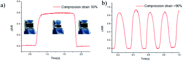 |
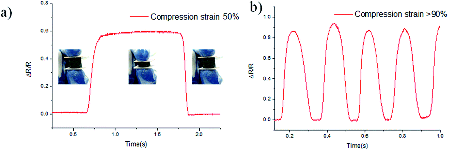
| | Fig. 5 (a) The change of electrical resistance of the PGS at ε = 50%; inset picture: the ceramic plates sintering together with PGS to reinforce the electrical contact between the copper wires and PGS, showing the compression and release circle manually. (b) The frequency response of the PGS to periodic changes under a repetitive pressure. | |
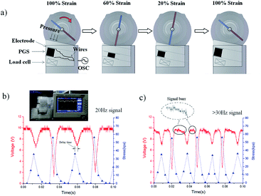 |
| | Fig. 6 (a) A schematic illustrating rotating blades of different lengths (marked in blue and red) driving the PGS to two compression ratios in one cycle. The compression strain of PGS is related to the lengths of the single blade. (b) The frequency response (red curve) of the PGS for the dynamic piezoresistive measurement and the load cell (force sensor) synchronously monitoring the pressure values (blue curve). Inset shows the output of this experimental setup being monitored and measured on an oscilloscope. (c) A higher frequency output of PGS over 30 Hz dynamic loading. | |
4 Conclusions
In summary, graphene sponge was successfully prepared by an environmentally friendly freeze-drying process. The stable porous structure and highly compressible conductive network allows the composites to have peculiar piezoresistive behavior with tunable sensitivity (0.75 to 3.08 kPa−1) and a fast response time (14 ms). In order to test the dynamic response of our PGS sensor, a homemade device was designed to sense the waveform and analyze the delay ratio of the frequency loading. A synchronous response could be observed with a decrease in the delay ratio from 18% to 7% between 20–35 Hz, which is unusual for traditional pressure sensors based on a single rubber matrix. The adopted nanoscale architecture combined the intrinsic properties of each component, which provides a promising effective strategy for wider development of novel materials and applications.
Acknowledgements
This research was supported by the Fundamental Research Funds for the Central Universities (HUST: No. 2016YXMS205), and the Creative Technology Project of Hubei Province: No. 2016AAA048.
References
- Z. Chen, W. Ren, L. Gao, B. Liu, S. Pei and H. M. Cheng, Nat. Mater., 2011, 10, 424–428 CrossRef CAS PubMed.
- C. Li and G. Shi, Nanoscale, 2012, 4, 5549–5563 RSC.
- H. B. Yao, J. Ge, C. F. Wang, X. Wang, W. Hu, Z. J. Zheng, Y. Ni and S. H. Yu, Adv. Mater., 2013, 25, 6692–6698 CrossRef CAS PubMed.
- S. Nardecchia, D. Carriazo, M. L. Ferrer, M. C. Gutiérrez and M. F. Del, Chem. Soc. Rev., 2013, 42, 794–830 RSC.
- J. Li, J. Li, H. Meng, S. Xie, B. Zhang, L. Li, H. Ma, J. Zhang and M. Yu, J. Mater. Chem. A, 2014, 2, 2934–2941 CAS.
- V. Chabot, D. Higgins, A. Yu, X. Xiao, Z. Chen and J. Zhang, Energy Environ. Sci., 2014, 7, 1564–1596 CAS.
- L. Qiu, J. Z. Liu, S. L. Y. Chang, Y. Wu and D. Li, Nat. Commun., 2012, 3, 187–190 Search PubMed.
- J. L. Vickery, A. J. Patil and S. Mann, Adv. Mater., 2009, 21, 2180–2184 CrossRef CAS.
- E. Singh, Z. Chen, F. Houshmand, W. Ren, Y. Peles, H. Cheng and N. Koratkar, Small, 2013, 9, 2 CrossRef.
- H. Hu, Z. Zhao, W. Wan, Y. Gogotsi and J. Qiu, ACS Appl. Mater. Interfaces, 2014, 6, 3242 CAS.
- H. Liu, M. Dong, W. Huang, J. Gao, K. Dai, J. Guo, G. Zheng, C. Liu, C. Shen and Z. Guo, J. Mater. Chem. C, 2017, 5, 73–83 RSC.
- H. Tian, Y. Shu, X. F. Wang, M. A. Mohammad, Z. Bie, Q. Y. Xie, C. Li, W. T. Mi, Y. Yang and T. L. Ren, Sci. Rep., 2015, 5, 8603 CrossRef CAS PubMed.
- C. Wu, X. Huang, X. Wu, R. Qian and P. Jiang, Adv. Mater., 2013, 25, 5658 CrossRef CAS PubMed.
- S. Jung, J. H. Kim, J. Kim, S. Choi, J. Lee, I. Park, T. Hyeon and D.-H. Kim, Adv. Mater., 2014, 26, 4825–4830 CrossRef CAS PubMed.
- H. Liu, M. Dong and W. Huang, et al., J. Mater. Chem. C, 2017, 5(1), 73–83 RSC.
- T. Liu, M. Huang, X. Li, C. Wang, C.-X. Gui and Z.-Z. Yu, Carbon, 2016, 100, 456–464 CrossRef CAS.
- L. Qiu, C. M. Bulut, Y. Tang, J. Z. Liu, T. Alan, J. Ding, V. T. Truong and D. Li, Adv. Mater., 2016, 28, 194–200 CrossRef CAS PubMed.
- W. S. Hummers and R. E. Offeman, J. Am. Chem. Soc., 1958, 80, 1339 CrossRef CAS.
- D. C. Marcano, D. V. Kosynkin, J. M. Berlin, A. Sinitskii, Z. Sun, A. Slesarev, L. B. Alemany, W. Lu and J. M. Tour, ACS Nano, 2010, 4, 4806 CrossRef CAS PubMed.
- C. Zhu, S. Guo, Y. Fang and S. Dong, ACS Nano, 2010, 4, 2429–2437 CrossRef CAS PubMed.
- Z. Xu and M. J. Buehler, ACS Nano, 2010, 4, 3869–3876 CrossRef CAS PubMed.
- H. Zhao and J. Bai, ACS Appl. Mater. Interfaces, 2015, 7, 9652–9659 CAS.
- B. Zhang, B. Li and S. Jiang, Composites, Part A, 2017, 94, 124–132 CrossRef CAS.
- C. Yan, J. Wang, W. Kang, M. Cui, X. Wang, C. Y. Foo, K. J. Chee and P. S. Lee, Adv. Mater., 2014, 26, 2022–2027 CrossRef CAS PubMed.
- J. Cui, B. Zhang, J. Duan, H. Guo and J. Tang, Sensors, 2016, 16, 2131 CrossRef PubMed.
- T. Zhai, D. Li, G. Fei and H. Xia, Composites, Part A, 2015, 72, 108–114 CrossRef CAS.
- H. Tian, Y. Shu and X. F. Wang, et al., Sci. Rep., 2015, 5, 8603 CrossRef CAS PubMed.
- R. Kazemzadeh, K. Andersen, L. Motha and W. S. Kim, IEEE Electron Device Lett., 2015, 36, 180–182 CrossRef CAS.
- C. S. Boland, U. Khan, G. Ryan, S. Barwich, R. Charifou, A. Harvey, C. Backes, Z. Li, M. S. Ferreira and M. E. Möbius, et al., Science, 2016, 354, 1257–1260 CrossRef CAS PubMed.
|
| This journal is © The Royal Society of Chemistry 2017 |
Click here to see how this site uses Cookies. View our privacy policy here. 
 Open Access Article
 This Open Access Article is licensed under a
  ,
Qi Xiao
,
Qi Xiao