
 Open Access Article
 This Open Access Article is licensed under a
 Creative Commons Attribution 3.0 Unported Licence
The optical selection rules of a graphene quantum dot in external electric fields
Qing-Rui Dong and
Chun-Xiang Liu *
*
School of Physics and Electronics, Shandong Normal University, Jinan, Shandong 250014, People's Republic of China. E-mail: qrdong@sdnu.edu.cn
First published on 26th April 2017
Abstract
We study theoretically the single-electron triangular zigzag graphene quantum dot in three typical in-plane electric fields. The far-infrared absorption spectra of the dot are calculated by the tight-binding method and then the optical selection rules are identified by contrast with the corresponding energy spectra. Our result shows that there exist the remarkable optical selection rules due to the C3 symmetry of the dot. When the electric field possesses also the C3 symmetry, there are only two absorption peaks in the absorption spectra. As the C3 symmetry of the system is damaged by the electric fields, both the intensity of the strongest peak and the number of the forbidden transitions decrease gradually. Moreover, the polarization causes the decrease of the peak intensities and even new forbidden transitions. Our findings may be useful for the application of graphene quantum dots to electronic and optoelectronic devices.
I. Introduction
Graphene, a single layer of carbon atoms arranged in a two-dimensional honeycomb lattice, was first successfully fabricated in 2004.1 Due to the exceptional properties, such as massless carrier behavior,2 high carrier mobility at room temperature,3 superior thermal conductivity,4 extremely high tensile strength5 and high transparency to incident light over a large wavelength range,6 graphene has attracted enormous research interest and exhibited great application potential in next-generation electronics7 and optoelectronics.8 Much of the current understanding of the electronic properties of graphene has been reviewed by Castro-Neto,9 transport properties by Das Sarma10 and many-body effects by Kotov.11 However, a gap has to be induced in the gapless graphene for its real applications in electronic devices. For this purpose, graphene quantum dots (GQDs) have been proposed as one of the most promising kinds of graphene nanostructures.12 GQDs exhibit the unique electronic, spin and optical properties, which allow them hold great application potential in electronics and optoelectronics such as super capacitor,13 flash memory,14 photodetector15 and phototransistor.16 On the other hand, with recent developments of fabrication techniques, it is possible to cut accurately the bulk graphene into different sizes and shapes, such as hexagonal zigzag quantum dots, hexagonal armchair quantum dots, triangular zigzag quantum dots and triangular armchair quantum dots.17Further applications of GQDs require a thorough knowledge of their electronic properties. The electronic and magnetic properties of GQDs depend strongly on their shapes and edges.18–20 Moreover, for zigzag GQDs, especially triangular GQDs (TGQDs), there appears a shell of degenerate states at the Dirac points and the degeneracy is proportional to the edge size.21,22 The electronic states of TGQDs can be classified by the group theory according to irreducible representations of the C3 symmetry group.12 As a result of the degenerate zero-energy band, magnetism arising in graphene nanostructures (nanoflakes, quantum dots and nanoribbons) has recently collected rich literature.23–25 The key feature for device application of GQDs is the ability to manipulate their electronic structures. Therefore, one of the flourishing fields of exploration is the influence of external fields on the degenerate zero-energy band.26 The electronic structure and magnetization relating to the zero-energy band can be manipulated electrically,27–29 optically30 and magnetically.31,32 In particular, the electrical manipulation of the zero-energy band of such GQDs is quite important for the operation of related devices, since it is easier to generate the potential field through local gate electrodes than the optical or magnetic field. However, it is rather rare to study the influence of electric fields on the optical properties relating to the zero-energy band.33
The advantage of applying external electric fields is that these fields can adjust the splitting of the degenerate zero-energy band and then can adjust the optical transition wavelength. Without external fields, the ability to adjust the optical performance of the related devices will be greatly limited. In this paper, we concentrate on the effects of three typical in-plane electric fields on the far-infrared (FIR) absorption spectra of a TGQD. Our result shows that there exist the remarkable selection rules in the FIR spectra due to the C3 symmetry of the dot. When the electric field possesses also the C3 symmetry, there are only two absorption peaks in the FIR spectra. As the C3 symmetry of the system is damaged by the electric fields, both the intensity of the strongest peak and the number of the forbidden transitions decrease gradually. Our findings may be useful for the application of GQDs to electronic and optoelectronic devices.
II. Model and method
In order to study the FIR spectrum of a single-electron GQD, we propose a scheme for the single-electron system. The theoretical basis of this scheme is the Coulomb blockade effect in GQDs.34 The number of electrons in the dot is determined by the condition that the chemical potential of the dot is less than that of the leads (source and drain).35 The chemical potential of the dot μ(N) is defined as μ(N) = EG(N) − EG(N − 1), where EG(N) is the ground-state energy of the N-electron system. For a single-electron system, more simply, μ(1) = EG(1). In other words, the single-electron system can be obtained if the ground-state energy of the system is slightly lower than the chemical potential of the leads.The low-energy electronic structure of a GQD subjected to an in-plane electric field can be calculated by means of the tight-binding method.22,27 In the low-energy range, the tight-binding Hamiltonian with the nearest-neighbor approximation proves to give the same accuracy as first-principle calculations.36 The Hamiltonian equation of the system is H|Ψ(r)〉 = E|Ψ(r)〉 and the tight-binding Hamiltonian with the nearest-neighbor approximation is37
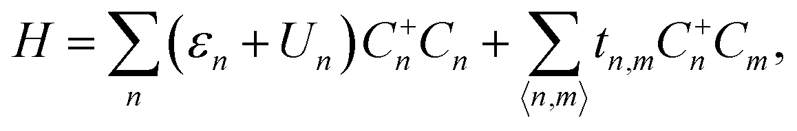 | (1) |
Using the Fermi golden rule with the electric-dipole approximation for the perturbing unpolarized light, the transition probability from the ground state to the lth excited state can be calculated as33,38
| Al ∝ |〈Ψl|r|Ψ0〉|2δ(El − E0 − ħω), | (2) |
In addition to that, one selected spectrum can be decomposed to x and y polarization,
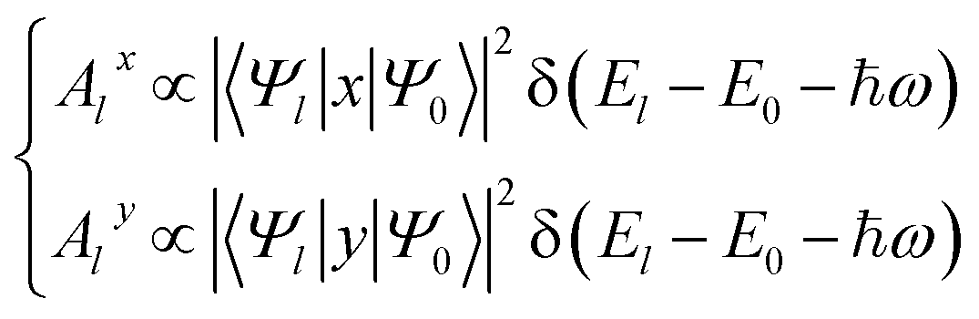 | (3) |
According to the irreducible theory of the symmetry group,39 symmetry leads to selection rules or forbidden transitions. For the same system, the transition matrix element for the polarized light Alx or Aly is a component of Al. Thus, the polarization may cause the decrease of the transition probabilities and even forbidden transitions.
III. The electric fields and the FIR spectra
A. Three typical in-plane electric fields
In Fig. 1, three typical in-plane electric fields are applied respectively to a TGQD with the size Ns = 8, where Ns is the number of carbon atoms in each side of the dot. Each electric field is generated by two gate electrodes with opposite electrostatic potentials ±U. In the following, the symmetry characteristics of the three electric fields are analyzed simply. In Fig. 1(a), the triangular electric field EF1 possesses the same C3 rotation symmetry as the quantum dot. In Fig. 1(b), the uniform electric field EF2 damages the C3 symmetry of the system even though it is homogeneous. In Fig. 1(c), the random electric field EF3 presents randomly an imaginary potential distribution, which simulates an electric field with irregular gate electrodes. In contrast, EF1 does not change the symmetry of the system while EF3 causes the most serious damage to the symmetry of the system.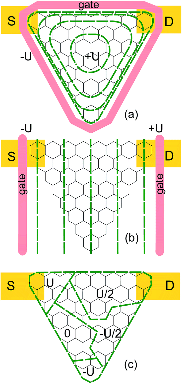 | ||
| Fig. 1 The electric fields applied to a TGQD (Ns = 8). (a) The triangular electric field EF1 with a C3 rotation symmetry, where two gates with electrostatic potentials ±U are applied outside and bottom of the dot. (b) The uniform electric field EF2, where two gates with electrostatic potentials ±U are applied to the left and right of the dot. (c) The random electric field EF3 which presents randomly an imaginary potential distribution. The contour of the electrostatic potential is shown (green dashed curves). The leads S and D are also labelled. | ||
B. The FIR spectra and the selection rules
Fig. 2 shows the energy spectra and the calculated FIR spectra of a single-electron TGQD (Ns = 8). The energy spectra are shown in Fig. 2(a–c) and the more details of the energy spectra can be seen elsewhere.40 According to the ground-state level and the chemical potential of the leads, one can guarantee that there is only one electron in the dot. The calculated FIR spectra are shown in Fig. 2(d–f) and the corresponding optical selection rules are marked on the energy spectra. In the FIR spectra, we consider only the optical transitions where the excited states are the zero-energy band and the four lowest states of the non-zero band. Moreover, we have included only the transitions which have a peak intensity of more than 1% of the maximum value. Also, we have plotted the intensities of the absorption peaks for the intraband transitions in Fig. 3(a–c) and those for the interband transitions in Fig. 3(e) and (f). Fig. 3 makes it easier to compare the difference between the intraband transitions and the interband transitions. As a general feature of the calculated spectra shown in Fig. 2(d–f), one can see that each spectrum has two branches as a major component, where the higher one comes from the interband transitions and the lower from the intraband transitions. According to the energy spectra, the specific selection rules can be identified easily. These forbidden transitions are attributed to the C3 rotational symmetry of the dot.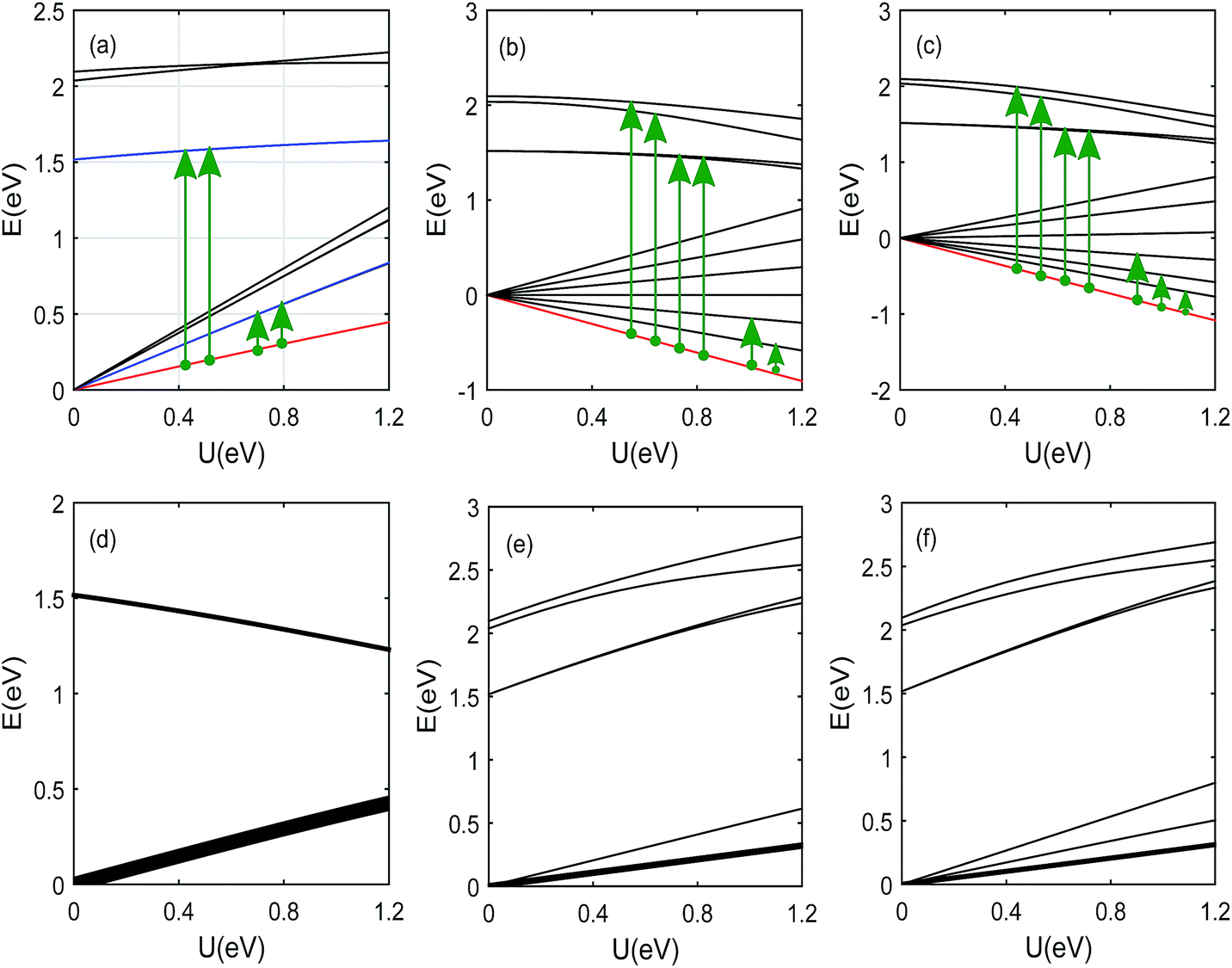 | ||
| Fig. 2 The energy spectra and the FIR spectra of a TGQD (Ns = 8). (a) The energy spectra with EF1 where the blue lines correspond to the double degenerate levels. (b) The energy spectra with EF2. (c) The energy spectra with EF3. (d) The FIR spectra with EF1. (e) The FIR spectra with EF2. (f) The FIR spectra with EF3. In (a–c), the red lines correspond to the ground-state levels and the green arrows indicate the selection rules. In (d–f), the line width is roughly proportional to the peak intensity. | ||
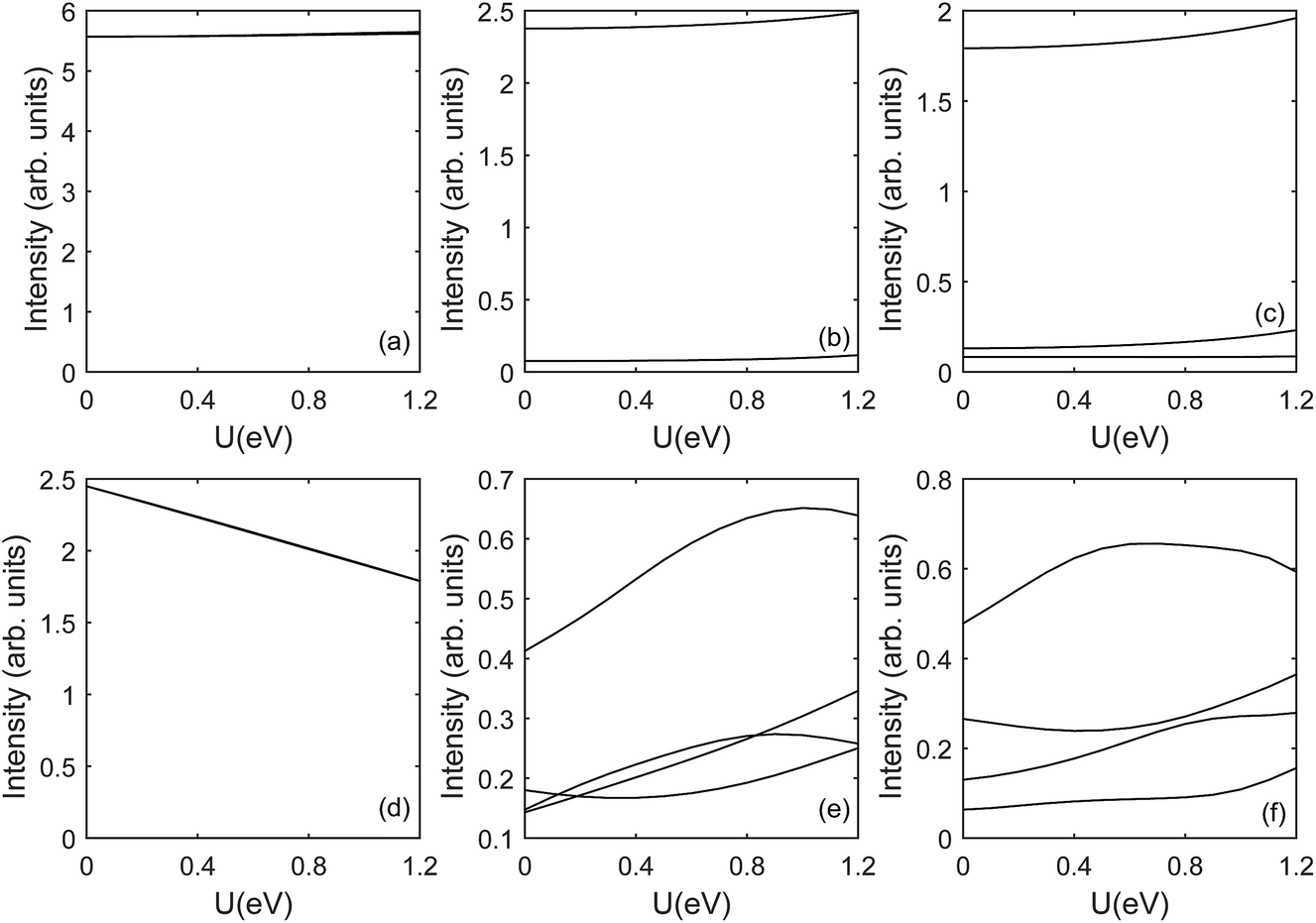 | ||
| Fig. 3 The intensities of the absorption peaks for the intraband and interband transition in a TGQD (Ns = 8). (a) The intraband transition with EF1. (b) The intraband transition with EF2. (c) The intraband transition with EF3. (d) The interband transition with EF1. (e) The interband transition with EF2. (f) The interband transition with EF3. | ||
The effects of three electric fields on the FIR spectra are compared in the following. The electric field EF1 possesses a C3 rotational symmetry and thus the C3 symmetry of the system is not damaged. Fig. 2(d) shows the FIR spectra of the dot subjected to the triangular electric field EF1. In the absorption spectrum, there are only two absorption peaks. One peak comes from the intraband transition and the other comes from the interband transition. The selection rule is marked in Fig. 2(a). Fig. 3(a) and (d) shows that the intensity of the interband peak is less than half the intensity of the intraband peak. It should be noted that the excited level of the intraband transition is double degenerate and the two degenerate states contribute the same peak intensity. Therefore, the peak intensity should be multiplied by two if the data are measured experimentally. This kind of degeneracy can also be seen in the interband transition. Later it will be shown that the x or y polarization breaks the balance of the peak intensities due to the degeneracy.
Fig. 2(e) shows the FIR spectra of the dot subjected to the uniform electric field EF2. There appear two absorption peaks in the intraband transition and Fig. 3(b) shows the intensity of the second intraband peak is about 5% of the intensity of the strongest intraband peak. The transitions from the ground state to the non-zero band are all allowed. The selection rule is marked in Fig. 2(b). Fig. 3(b) and (e) shows that the intensity of the strongest interband peak is about 25% of the intensity of the strongest intraband peak. In contrast to the situation with EF1, both the intensity of the strongest peak and the number of the forbidden transitions decrease significantly. The phenomenon suggests that the C3 symmetry of the system has been damaged to a certain extent.
Fig. 2(f) shows the FIR spectra of the dot subjected to the random electric field EF3. There appear three intraband absorption peaks in the spectra. Fig. 3(c) shows that the intensity of the second intraband peak is about 10% of the intensity of the strongest intraband peak and the intensity of the third intraband peak is about 5% of the intensity of the strongest intraband peak. The transitions from the ground state to the non-zero band are all allowed. The selection rule is marked in Fig. 2(c). Fig. 3(c) and (f) shows that the intensity of the strongest interband peak is about 30% of the intensity of the strongest intraband peak. In contrast to the situation with EF2, the intensity of the strongest peak and the number of the forbidden transitions decreases further. The phenomenon suggests that the disorder of the random electric field has damaged further the C3 symmetry of the system.
From the electric field EF1 to EF2 and then to EF3, the C3 symmetry of the system is damaged gradually. Therefore, both the intensity of the strongest peak and the number of the forbidden transitions decrease gradually. These phenomenons can also be explained in view of the wave function. As the symmetry is damaged, the eigenstates are recombined and the wave function component that allows the transition are dispersed, which leads to more absorption peaks. The intensities of the intraband peaks are almost constant with U while the intensities of the interband peaks change drastically with U. The reason is that the eigenstates of the zero-energy band are almost constant with U while the eigenstates of the nonzero-energy band are mixed continuously with U.40
C. The effect of polarization on the FIR spectra
In the following, we investigate the effect of x and y polarization on the FIR spectra by comparing the polarized spectra with the unpolarized spectra. Fig. 4(a) shows the x- and y-polarized FIR spectra of the dot subjected to the electric field EF1. Compared with the unpolarized spectra, the peak energies of the x- and y-polarized spectra do not change while the peak intensities change significantly. The balances of the peak intensities due to the degeneracy are broken since the polarization reduces some relevant transition matrix element. Although the system is asymmetric in the x and y directions, the effects of the x and y polarization on the spectra are similar. This coincidence may be related to the specific distribution of the wave function. Fig. 4(b) shows the x- and y-polarized FIR spectra of the dot subjected to the electric field EF2. A remarkable phenomenon is that all the intraband transitions are forbidden in the x-polarized spectrum. In the y-polarized spectrum, the peak energies are the same as the unpolarized spectra as shown in Fig. 2(e). The peak intensities of the unpolarized spectra are allocated unequally to the x- and y-polarized spectra, which is consistent with eqn (2) and (3). Fig. 4(c) shows the x- and y-polarized FIR spectra of the dot subjected to the electric field EF3. The peak energies in the x- and y-polarized spectra are the same as the unpolarized spectra as shown in Fig. 2(f). In other words, the selection rules are not changed by the x and y polarization. The peak intensities of the unpolarized spectra are allocated roughly equally to the x- and y-polarized spectra. This fact shows that the polarization can not generate any new forbidden transition. This phenomenon implies that the random electric field causes more damage to the C3 symmetry than the electric fields EF2. By comparing the polarized spectra with the unpolarized spectra, it can be seen that the polarization causes the decrease of the peak intensities and even the new forbidden transitions. Moreover, the effects of the polarization are related closely to the symmetry of the electric fields.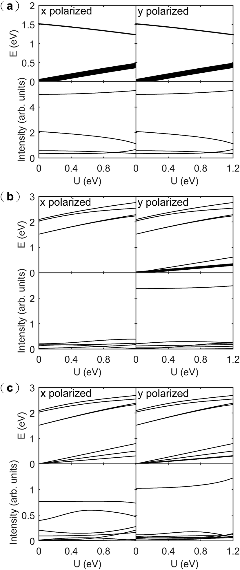 | ||
| Fig. 4 The x- and y-polarized FIR spectra of a TGQD (Ns = 8) (a) subjected to EF1, (b) subjected to EF2 and (c) subjected to EF3. In each panel, the left side corresponds to the x polarization, the right side to the y polarization, the upper side to the peak energy and the lower side to the peak intensity. The width of each line for the peak energy is roughly proportional to the corresponding peak intensity. | ||
IV. Summary
In this paper, we have investigated the effects of three typical in-plane electric fields on the FIR spectra of a single-electron triangular zigzag graphene quantum dot. Our result shows that there exist the remarkable selection rules in the FIR spectra due to the C3 symmetry of the dot. When the electric field possesses also the C3 symmetry, there are only two absorption peaks. As the C3 symmetry of the system is damaged by the electric fields, both the intensity of the strongest peak and the number of the forbidden transitions decrease gradually. The intensities of the intraband peaks are almost constant with U while the intensities of the interband peaks change drastically. The polarization causes the decrease of the peak intensities and even the new forbidden transitions. These findings suggest that special attention should be paid to the selection rules when designing TGQD optoelectronic devices. On the other hand, the selection rules can enrich the means of manipulating related optoelectronic devices. Our findings may help to probe the electronic structure of GQDs by FIR spectroscopy and may be useful for the application of GQDs to electronic and optoelectronic devices.Acknowledgements
This work is supported by the National Natural Science Foundation of China (Grant No. 11604183 and 11674197), and a Project of Shandong Province Higher Educational Science and Technology Program (Grant No. J16LJ09).References
- K. S. Novoselov, A. K. Geim, S. V. Morozov, D. Jiang, Y. Zhang, S. V. Dubonos, I. V. Grigorieva and A. A. Firsov, Science, 2004, 306, 666 CrossRef CAS PubMed.
- M. I. Katsnelson, K. S. Novoselov and A. K. Geim, Nat. Phys., 2006, 2, 620 CrossRef CAS.
- K. I. Bolotin, K. J. Sikes, Z. Jiang, M. Klima, G. Fudenberg, J. H. P. Kim and H. L. Stormer, Solid State Commun., 2008, 146, 351 CrossRef CAS.
- A. A. Balandin, S. Ghosh, W. Bao, I. Calizo, D. Teweldebrhan, F. Miao and C. N. Lau, Nano Lett., 2008, 8, 902 CrossRef CAS PubMed.
- C. Lee, X. Wei, J. W. Kysar and J. Hone, Science, 2008, 321, 385–388 CrossRef CAS PubMed.
- R. R. Nair, P. Blake, A. N. Grigorenko, K. S. Novoselov, T. J. Booth, T. Stauber, N. M. Peres and A. K. Geim, Science, 2008, 320, 1308 CrossRef CAS PubMed.
- K. S. Novoselov, V. I. Fal’ko, L. Colombo, P. R. Gellert, M. G. Schwab and K. Kim, Nature, 2012, 490, 192 CrossRef CAS PubMed.
- F. Xia, H. Wang, D. Xiao, M. Dubey and A. Ramasubramaniam, Nat. Photonics, 2014, 8, 899 CrossRef CAS.
- A. C. Neto, F. Guinea, N. M. Peres, K. S. Novoselov and A. K. Geim, Rev. Mod. Phys., 2009, 81, 109 CrossRef.
- S. D. Sarma, S. Adam, E. Hwang and E. Rossi, Rev. Mod. Phys., 2011, 83, 407 CrossRef.
- V. N. Kotov, B. Uchoa, V. M. Pereira, F. Guinea and A. C. Neto, Rev. Mod. Phys., 2012, 84, 1067 CrossRef CAS.
- A. D. Güçlü, P. Potasz, M. Korkusinski and P. Hawrylak, Graphene quantum dots, Springer, 2014 Search PubMed.
- W.-W. Liu, Y.-Q. Feng, X.-B. Yan, J.-T. Chen and Q.-J. Xue, Adv. Funct. Mater., 2013, 23, 4111 CrossRef CAS.
- S. S. Joo, J. Kim, S. S. Kang, S. Kim, S.-H. Choi and S. W. Hwang, Nanotechnology, 2014, 25, 255203 CrossRef PubMed.
- C. O. Kim, S. W. Hwang, S. Kim, D. H. Shin, S. S. Kang, J. M. Kim, C. W. Jang, J. H. Kim, K. W. Lee and S.-H. Choi, et al., Sci. Rep., 2014, 4, 5603 CrossRef CAS PubMed.
- G. Konstantatos, M. Badioli, L. Gaudreau, J. Osmond, M. Bernechea, F. P. G. De Arquer, F. Gatti and F. H. Koppens, Nat. Nanotechnol., 2012, 7, 363 CrossRef CAS PubMed.
- M. Bacon, S. J. Bradley and T. Nann, Part. Part. Syst. Charact., 2014, 31, 415 CrossRef CAS.
- A. D. Güclü, P. Potasz, O. Voznyy, M. Korkusinski and P. Hawrylak, Phys. Rev. Lett., 2009, 103, 246805 CrossRef PubMed.
- D. Abergel, V. Apalkov, J. Berashevich, K. Ziegler and T. Chakraborty, Adv. Phys., 2010, 59, 261–482 CrossRef CAS.
- P. Potasz, A. D. Güclü, A. Wójs and P. Hawrylak, Phys. Rev. B: Condens. Matter Mater. Phys., 2012, 85, 075431 CrossRef.
- P. Potasz, A. D. Güçlü and P. Hawrylak, Phys. Rev. B: Condens. Matter Mater. Phys., 2010, 81, 033403 CrossRef.
- F. X. Liang, Z. T. Jiang, Z. T. Lv, H. Y. Zhang and S. Li, J. Appl. Phys., 2014, 116, 123706 CrossRef.
- Y. Sun, Y. Zheng, H. Pan, J. Chen, W. Zhang, L. Fu, K. Zhang, N. Tang and Y. Du, npj Quantum Materials, 2017, 2, 5 CrossRef.
- T. Basak and A. Shukla, Phys. Rev. B: Condens. Matter Mater. Phys., 2016, 93, 235432 CrossRef.
- P. Hawrylak, F. Peeters and K. Ensslin, Phys. Status Solidi RRL, 2016, 10, 11 CrossRef CAS.
- R. Farghadan and A. Saffarzadeh, J. Appl. Phys., 2014, 115, 174310 CrossRef.
- R. B. Chen, C. P. Chang and M. F. Lin, Phys. E, 2010, 42, 2812 CrossRef CAS.
- W. L. Ma and S. S. Li, Phys. Rev. B: Condens. Matter Mater. Phys., 2012, 86, 045449 CrossRef.
- Q. R. Dong, J. Appl. Phys., 2013, 113, 234304 CrossRef.
- A. D. Güclü and P. Hawrylak, Phys. Rev. B: Condens. Matter Mater. Phys., 2013, 87, 035425 CrossRef.
- K. Szałowski, J. Magn. Magn. Mater., 2015, 382, 318–327 CrossRef.
- L. L. Li, M. Zarenia, W. Xu, H. M. Dong and F. M. Peeters, Phys. Rev. B: Condens. Matter Mater. Phys., 2017, 95, 045409 CrossRef.
- H. Abdelsalam, M. Talaat, I. Lukyanchuk, M. Portnoi and V. Saroka, J. Appl. Phys., 2016, 120, 014304 CrossRef.
- J. Güttinger, F. Molitor, C. Stampfer, S. Schnez, A. Jacobsen, S. Dröscher, T. Ihn and K. Ensslin, Rep. Prog. Phys., 2012, 75, 126502 CrossRef PubMed.
- W. G. van der Wiel, S. De Franceschi, J. M. Elzerman, T. Fujisawa, S. Tarucha and L. P. Kouwenhoven, Rev. Mod. Phys., 2003, 75, 1 CrossRef CAS.
- D. S. L. Abergel, V. Apalkov, J. Berashevich, K. Ziegler and T. Chakraborty, Adv. Phys., 2010, 59, 261 CrossRef CAS.
- W. L. Ma and S. S. Li, Appl. Phys. Lett., 2012, 100, 163109 CrossRef.
- Q.-R. Dong, C.-X. Liu, S.-Y. Teng, N.-Y. Zhang and C.-F. Cheng, J. Phys. D: Appl. Phys., 2007, 40, 730 CrossRef CAS.
- J. Elliott and P. Dawber, Symmetry in Physics, Macmillan, 1979, vol. 1 and 2 Search PubMed.
- Q.-R. Dong, RSC Adv., 2014, 4, 12287 RSC.
| This journal is © The Royal Society of Chemistry 2017 |