DOI:
10.1039/C7RA03563B
(Paper)
RSC Adv., 2017,
7, 30673-30686
Influence of magnetohydrodynamic viscous flow on entropy generation within porous micro duct using the Lattice Boltzmann Method
Received
28th March 2017
, Accepted 12th May 2017
First published on 14th June 2017
Abstract
In this work entropy generation and heat transfer for magnetohydrodynamic (MHD) forced convection flow in a micro duct filled with a porous medium are investigated using a modified axisymmetric Lattice Boltzmann Method. In modeling the flow, the Brinkman–Forchheimer-extended Darcy model is incorporated in momentum equations. The Local Thermal Non-Equilibrium (LTNE) assumption between fluid and solid phases is adopted to investigate heat transfer. All terms of viscous dissipation effects are included in the energy equation of the fluid phase. Our attention is focused on the effects of different values of Hartmann number Ha, Knudsen number, Kn, Eckert number, Ec, and Biot number, Bi, on the flow, Nusselt number and entropy generation.
1. Introduction
The flow phenomenon in a porous microfluidic channel has been analyzed by many researchers. This is thanks to its important applications in biochemistry, biomedicines, fuel cells and heat exchange.1,2 The fluid flow in these fields is effectively actuated by electrical fields, magnetic fields, or their suitable combinations. Among the different effects, magnetohydrodynamic (MHD) micro-systems have attracted the attention of many researchers3,4 due to their prospective applications in microfluidic systems in recent years. Jian5 provided the transient MHD heat transfer and entropy generation in a micro-parallel channel combined with pressure and electro-osmotic effects. Das et al.6 illustrated certain applications of the MHD pumps such as sample injection, fluid flow in packs bed and on-chip assay development. Ellahi7 studied the magnetohydrodynamic flow of non-Newtonian nano fluids in a pipe and discussed the effects of various physical parameters on fluid flow and heat transfer. He demonstrates that the Hartmann number Ha, reduces the fluid motion and that the velocity profile is larger than that of the temperature profile. Aminossadati et al.8 investigated the effects of magnetic field on nanofluid forced convection in a partially heated micro channel. In their study, the Local thermal Equilibrium (LTE) model is used and the effect of the viscous dissipation is neglected.
Due to the complex structure of porous metals together with the computational consumption, the molecular dynamic method is limited to a volume containing finite particles. As a novel numerical approach, the Lattice Boltzmann Method (LBM) is introduced to investigate the structures of the ferrofluid.9,10 Recently, the Lattice Boltzmann Method originating from the kinetic Boltzmann equation became popular over the past few years. It considers a fluid as a set of artificial particles and explores the microscopic features of the fluid by using the collision effect among these particles. There are two Lattice Boltzmann models for simulating MHD flows: the multispeed (MS) model and multi-distribution function (MDF) model. In the MDF model, presented by Dellar,11,12 the Lorentz force can be introduced as a point-wise force, the induction equation is also solved using an Lattice Bhatnagar–Gross–Krook model (LBGK) equation by introducing an independent distribution function. MDF models can improve the numerical stability.13,14
The second law of thermodynamics explains that energy is moves from high quality energy to low quality energy. Quality of energy during a process also considers the quantitative measurement of exergy, potential work and entropy, and non-potential work. Quality of energy during a process has also been described in the second law of thermodynamics. Entropy generation is responsible for system performance as this is proportional to the energy destruction. Most of entropy generation studies on porous media use the volume-averaged entropy generation which assumes the solid and fluid phases to be at thermal equilibrium. In the up-to-date literature, there are few studies on the entropy generation of porous media flow which consider the thermal non-equilibrium condition between the two phases in porous micro systems.15–20 Ting et al.15 studied the thermal non-equilibrium entropy generation based on differential method flow in a porous microchannel. A numerical study used a thermal non-equilibrium model to investigate the entropy generation of natural convection in a saturated porous cavity treated by Baytas.16 By using the same model, entropy generation analyses were performed on rarefied gaseous slip flows (Buonomo et al.17) and partially-filled porous media flows (Torabi et al.18). Similarly to previous publications, Ting et al.19 treated entropy generation of viscous dissipative nanofluid convection in asymmetrically heated porous microchannels with solid-phase heat generation. Moreover, Betchen and Straatman20 derived the volume-averaged form of entropy generation function for non-equilibrium heat transfer in high conductivity porous foams.
In sight of the limitations in the previous works, in this paper, a modified axisymmetric LBM scheme is employed to investigate the physics of flow, fluid–solid coupling heat transfer and entropy generation in a micro duct filled with porous medium including viscous dissipation effects under the local thermal non equilibrium assumptions. Furthermore, new developments concerns the magnetic field is used in order to investigate the magnetic field behavior.
The rest of the paper is organized as follows: firstly, the problem and the mathematical models are described including the LBM simulation of hydrodynamic flow, heat transfer and magnetic field. Secondly, the accuracy of the present code is examined in the code validation section. Finally, the results are discussed and a conclusion is given as a closure section.
2. Mathematical formulation
Consider the axisymmetric, hydrodynamically fully developed and laminar forced convection flow insider a micro duct filled with porous media. A schematic diagram of the physical model and coordinate system is shown in Fig. 1. In this analysis, the following convectional assumptions are made: flow is incompressible, porous medium is homogenous, isotropic and supposed to be in the Local Thermal Non-Equilibrium condition (LTNE) and all terms of viscous dissipation effects are included. It is also assumed that the fluid is flowing in the slip flow regime, corresponding to Knudsen numbers in the range of 10−3 ≤ Kn ≤ 10−1. In the slip flow regime, the velocity slip and temperature jump are applied at the walls of the micro duct. Furthermore, the flow is subjected to a uniform magnetic field. It is assumed that the induced magnetic field produced by the motion of an electrically conducting fluid is negligible compared to the applied magnetic field.
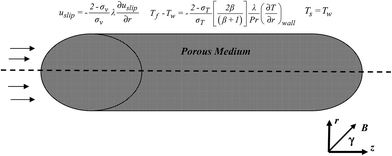 |
| | Fig. 1 Geometry and the coordinates system. | |
3. Lattice Boltzmann MHD model
3.1. Lattice Boltzmann equation for the velocity field
This section offers a general idea devoted to exploring an extended thermal Lattice Boltzmann model simulating flows under complex conditions. The results of the numerical examples demonstrate the potential of the LBM in dealing with this kind of problems. The LBM has been successfully applied to the simulation of axisymmetric flows.21 According the idea of Halliday et al.,21 in this paper we present a modified Lattice Boltzmann Equation (LBE), in which the source terms were added to the standard 2D LBE.22–26
In order to simulate the axisymmetric flows in a simple way, we extend the idea in a consistent manner to the original axisymmetric Lattice Boltzmann model to eliminate the calculations of the velocity gradients.27
| |
 | (1) |
In above equations, fα(z,t) is the dynamic distribution function for particles, Δt is the time increment, feqα is the equilibrium part of distribution function, fα(z + eαΔt,t + Δt) is the post-collision distribution function. z is the space vector, i.e., z = (r,z); e = Δz/Δt; Δz is the lattice size; ωα is the weight given by eqn (7); Θ is the source or sink term,
| |
 | (2) |
Fi is the force term defined by
| |
 | (3) |
i is the index standing for
r or
z;
r and
z are the coordinates in radial and axial directions, respectively;
ui is the component of velocity in
i direction;
δir is the Kronecker
δ function defined by
eαi is the component of
eα, which represents the velocity vector of a particle in the
α link;
κ is the constant and is determined from
| |
 | (4) |
And τα is an effective relaxation time related to the single relaxation time τ27 as
| |
 | (5) |
In this study, the density distribution function feqα is modified to consider the magnetic effect.27–30
| |
 | (6) |
where
B is the magnetic field and
ωα is the weight coefficient for the D2Q9 model is defined as:
| |
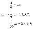 | (7) |
For axisymmetric D2Q9 model, the nine discrete velocities are defined as following:
| |
 | (8) |
From eqn (4), we have κ = 6.27
The fluid density ρ and velocity ui are determined from the distribution function in the same manner as that in the Lattice Boltzmann Method for the Navier–Stokes equations:
| |
 | (9) |
3.2. Lattice Boltzmann equations for the temperature fields
Accordingly to Gao et al.,31 the resolution of the energy equations is written as follows.| | |
gα(z + eαΔt,t + Δt) − gα(z,t) = −ωg[gα(z,t) − geqα(z,t)] + ΔtGα + Δtfα(z,t)qα + ΔtSrf,α
| (10) |
| |
 | (11) |
where gα(z,t) and hα(z,t) are respectively the temperature distribution functions for fluid and solid phases. geqα(z,t) and hα(z,t) is the equilibrium temperature distribution function and Gα is the source term. The relaxation parameter ωg is given by32| | |
ωg = [1 + (eirτgΔt/r)]/(τg + 0.5)
| (12) |
in which τg is the dimensionless relaxation time related towhere ζe,f is designated as the effective thermal diffusivity of the fluid phase.
τh is the relaxation time for the solid phase related to ζe,s via the following expression31
| |
 | (14) |
The single-particle equilibrium temperature distribution function has appropriate form for each phase and expressed as31,32
| |
 | (15) |
The source term Gα can be chosen as32
| |
 | (17) |
The two discrete heat source terms, Srf,α and Srs,α are given as31
| |
 | (18) |
| |
 | (19) |
According to Shi et al.,33 the term associated to viscous heat dissipation is as follows
| | |
qα = −(fα − feqα)(eα − u)(eα − u):∇u
| (20) |
The fluid and solid temperatures are given by:
| |
 | (21) |
3.3. Lattice Boltzmann equations for the magnetic field
For solving the magnetic field, the following equation must be considered:28–30| |
 | (22) |
where bα represents the magnetic field function and τm is the single relaxation time of the magnetic field and can be defined as:30η is the magnetic resistivity.
Similarly, the density equilibrium function (feqα), for calculating the magnetic field, magnetic equilibrium function is considered as follows:
| |
 | (24) |
| |
 | (25) |
Finally, microscopic variables are calculated with the following formulas:
| |
 | (26) |
4. Implementation of boundary conditions
4.1. Physical boundary conditions
Boundary conditions are very important for the accuracy and stability of LBM simulation. The unknown particle distribution functions at the boundary nodes must be calculated through proper boundary conditions (Fig. 2).
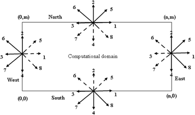 |
| | Fig. 2 D2Q9 lattice and velocities. | |
Two popular kinds of boundary conditions (BC) are used to impose the microscopic conditions on velocity and thermal fields. Velocity slip and the temperature jump are used at wall.15,34
| |
 | (27) |
where
uslip is the velocity slip,
σv is the tangential momentum accommodation coefficient and
λ is the molecular mean free path.
The symmetry condition at r = 0:
| |
 | (28) |
Boundary conditions of the energy equations include:
The symmetry condition at r = 0:
| |
 | (29) |
At the micro duct wall, the fluid temperature at the wall Tf can be different from that of the wall Tw and this temperature jump can be found as34
| |
 | (30) |
where Pr is the Prandtl number,
β is the specific heat ratio,
σT is the thermal accommodation coefficient.
4.2. LBM boundary conditions
4.2.1. Flow. For the north boundary conditions, the slip condition is used35 (Fig. 2).| |
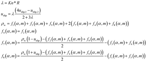 | (32) |
For the west boundary conditions, Zou and He condition36 is applied if the velocity is known. As for the east, open boundary37 is applied.
Another scheme imposed at the axis of the system is the axisymmetric boundary condition of the density distribution function which can be expressed by38
| | |
f2 = f4, f5 = f8, f6 = f7
| (33) |
4.2.2. Temperature. For the north boundary conditions, the temperature jump conditions is considered35| |
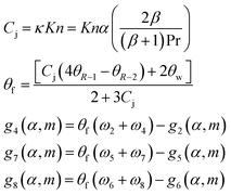 | (34) |
5. Entropy generation formulation for thermal non-equilibrium condition
Due to the existence of thermal non-equilibrium between the solid and fluid phases, the corresponding entropy generation differs from that with the assumption of Local Thermal Equilibrium between the two phases. In this section, the entropy generation for thermal non-equilibrium condition is formulated taking account the viscous dissipation effect and the magnetic field. For a point in the porous medium flow, the volumetric rate of the entropy generation for the present study can be expressed as.15,17–19,39,40| |
 | (35) |
| |
 | (36) |
The volumetric rate of entropy generation for thermal non-equilibrium porous medium flow can be obtained by adding eqn (35) and (36) Ṡ′′′gen = Ṡ′′′gen,s + Ṡ′′′gen,f to yield:
| |
 | (37) |
The first and second terms of eqn (37) represent heat transfer irreversibility produced by temperature gradients in the solid and the fluid phases, respectively. The third term refers to heat transfer irreversibility generated due to interstitial heat transfer at the solid–fluid interface of the porous medium. The fourth and fifth terms on the equation present the fluid friction irreversibility. The last term is due to the magnetic field. Therefore, the irreversibility components of entropy generation in the porous medium flow can be written as
| |
 | (38) |
| |
 | (39) |
where
Ṡ′′′HT is the volumetric rate of heat transfer irreversibility and
Ṡ′′′FF is the volumetric rate of fluid friction irreversibility.
The non-dimensional total entropy generation (Ns) can be expressed as eqn (40)
| |
 | (40) |
6. Code validation
In order to validate the present numerical code based on the modified LBM, our numerical results were quantitatively compared to the published ones for several cases. The first case concerns a forced convection of gaseous slip-flow in porous micro-channels under Local Thermal Non-Equilibrium conditions carried out by Haddad et al.41,42 The validation is devoted to the velocity and Nusselt number calculation expressed in the following form:| |
 | (41) |
where  and R*k = (1 − ε)ks/εkf
Fig. 3 and 4 show the velocity profile and Nusselt number distribution. It is noticeable that the velocity profile is parabolic and that the Nusselt number appears axially downstream in Fig. 4 because less heat transfer occurs from the wall to the fluid. The second case reported on the local thermal non equilibrium of the fluid and solid phases for different Knudsen numbers which is compared with results of Haddad et al.41 (Fig. 5).
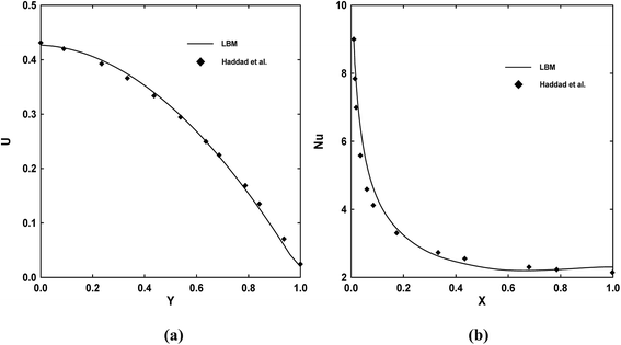 |
| | Fig. 3 Velocity profiles (a) and Nusselt number distributions (b) for case 1 (symbols: Haddad et al.,41 solid lines: present results (LBM)). | |
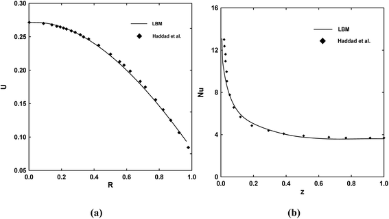 |
| | Fig. 4 Velocity profiles (a) and Nusselt number distributions (b) for case 2 (symbols: Haddad et al.,42 solid lines: present results (LBM)). | |
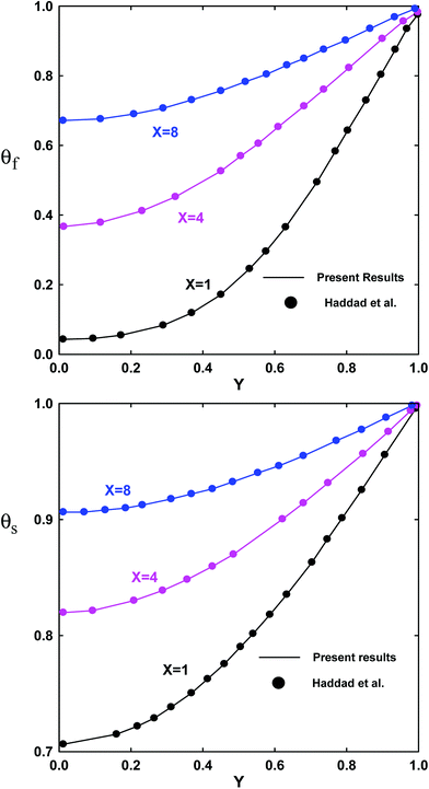 |
| | Fig. 5 Fluid and solid temperatures distribution (symbols: Haddad et al.,41 solid lines: present results (LBM)) for Kn = 10−3, Da = 1, Bi = 1and Rk = 0.1. | |
Another case is also corroborated by the numerical solution29 for a fully developed and laminar MHD flow between two parallel plates. In Fig. 6 a good agreement between the present study and the analytical solutions is shown for Ha = 1, 5 and 10. The results indicate the viability and reliability of the present Lattice Boltzmann model in modeling the MHD flow and fluid–solid coupling heat transfer in complex porous structures.
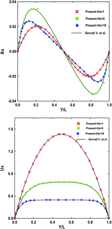 |
| | Fig. 6 A comparison of velocity profile (right) and magnetic field (left) in MHD flow between present study and exact analytical solution29 for Ha = 1, 5 and 10. | |
7. Results and discussion
We discussed the effects of different values of magnetic parameter Ha, Knudsen number, Kn, Eckert number, Ec, and Biot number, Bi, on the flow, Nusselt number and entropy generation. The considered slip-flow regime corresponds to Knudsen number ranging from 10−3 to 10−1 where the Reynolds number, the Prandtl number and porosity are chosen to be 20, 7 and 0.6 respectively. The default values of the other parameters are mentioned in the description of the respective figures.
7.1. Velocity distribution
Fig. 7a and b describe the effects of Knudsen and Hartmann numbers on the velocity profile. It can be observed from Fig. 7a that an increase in Kn leads to an increase in the velocities slip at walls. Therefore this trend is justified by the fact that an increase in Kn, which is related to a rise in the mean path of the molecule leads to a decrease in the retarding effect at the wall. The effects of Hartmann number Ha (1, 5 and 10) on the dimensionless velocity is shown in Fig. 7b. It can be found that increasing Ha tends to slow down the fluid motion. This trend can be explained by the application of the magnetic field to the micro duct creates a resistance force (Lorentz force) similar to the solid matrix force, which acts in the opposite direction of fluid movement causing the decrease of its speed.
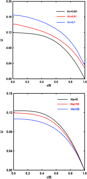 |
| | Fig. 7 Effect of Kn (a) and Ha (b) on the fully developed axial velocity profile. | |
Similarly, Fig. 8 and 9 plot magnetic field for different Knudsen (Kn) and Hartmann (Ha) numbers. It is found that the magnetic field varied with a change in Kn or Ha numbers. It is also observed from this figure that they have the same trend, the classic M-shaped velocity profile commonly observed in micro duct flows. This M-shaped velocity is driven purely by the magnetic field effects, and is the result of the same physical effect as the so-called magnetic collision. In the magnetic collision, the suspended magnetic particles tend to align their dipoles in the direction of the applied field. This particle response may hinder the movement of suspended magnetic particles and hence leads to an increase in the rate of energy dissipation of the flowing and eventually increases the effective viscosity of the suspension.
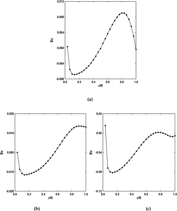 |
| | Fig. 8 Radial variation of the axial magnetic field for (a) Kn = 10−3 (b) Kn = 10−2 (c) Kn = 10−1 for Ha = 5, Da = 10−1, Ec = 5, γ = π/2 and Rk = 5. | |
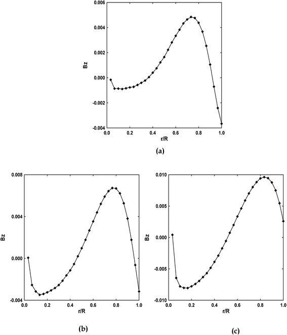 |
| | Fig. 9 Radial variation of the axial magnetic field for (a) Ha = 1, (b) Ha = 5, (c) Ha = 10 for Kn = 10−3, Da = 10−1, Ec = 5, γ = π/2 and Rk = 5. | |
7.2. Nusselt number
Having derived the velocity, the field and temperature distribution having been derived, we can further determine the Nusselt number (Nu), one of the most important dimensionless parameters in describing the strength of convective heat exchange. The local Nusselt number and the average Nusselt number are defined as follows41,42| |
 | (42) |
where  and R*k = (1 − ε)ks/εkf
And the average Nusselt number is:
| |
 | (43) |
Fig. 10–16 exhibit the influence of the dimensionless parameters (Kn, Ha, Ec and Bi) on local and average Nusselt numbers. It is notable from this figure that the curves have the same tendency. On the other hand, we can see the existence of a critical value of position depending on the emerging parameters (z < 1) for which Nu decreases in a monotonous way. Beyond this position, the Nusselt number tends to be almost constant along the micro-cylinder. The same figure (Fig. 10) shows that as Kn increases, Nu also increases. This is due to the reduction in heat transfer between the wall and the fluid. A similar behavior is observed for the average Nusselt number (Fig. 11), it improve with the increase of magnetic field. Therefore, the Nusselt number increases from a maximum near the input to an asymptotic value in the developed region of the flow regardless of the Knudsen number.
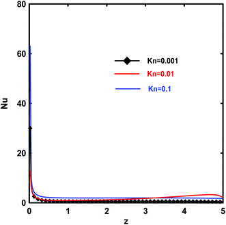 |
| | Fig. 10 Effects of Kn on the local Nusselt number, Nu, for Kn = 10−3, Da = 10−1, Ec = 5, γ = π/2 and Rk = 5. | |
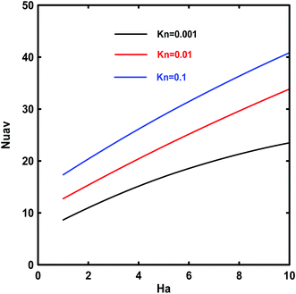 |
| | Fig. 11 Effects of Kn on the average Nusselt number, Nuav, vs. Hartmann number Ha for Ec = 5, Da = 10−1, Bi = 1, γ = π/2 and Rk = 5. | |
Fig. 12 shows the effect of magnetic field on the Nusselt number. For a given fluid and microchannel geometry, changes in Ha mean variations in the magnetic field. Results show that the increase of Hartmann number Ha results in a continuous reduction of Nusselt number Nu. The reason is that increasing Hartmann number causes Lorentz force to increase and leads to a substantial suppression of the convection. Therefore, Nusselt number has a reverse relationship with Hartmann number.
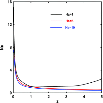 |
| | Fig. 12 Effects of Ha on the local Nusselt number for Kn = 10−3, Ha = 5, Ec = 5, γ=π/2 and Rk = 5. | |
The viscous dissipation effects on the local and average Nusselt numbers through the micro duct are displayed in Fig. 13 and 14. Generally, in a porous medium, viscous dissipation is made up of two components: internal heat generation denoted as Darcy term, and frictional heat generation denoted as Brinkman term. It is observed that the value of Eckert number, Ec, has an accelerating effect on the local Nu. The reason is that the viscous dissipation behaves like an energy source increasing the temperature of the fluid especially near the walls. By increasing the intensity of viscous dissipation, the values of Nuav indicate that the strength of flow and heat transfer flow increases. Therefore, the augmentation of the Eckert number increases the contribution of the heat transfer number due to fluid friction, heat and mass transfer in the micro duct.
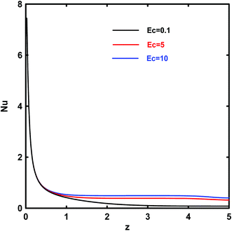 |
| | Fig. 13 Effects of Ec on the local Nusselt number for Kn = 10−3, Da = 10−1, γ = π/2 and Rk = 5. | |
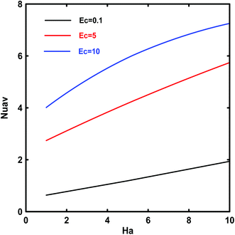 |
| | Fig. 14 Effects of Ec on the average Nusselt number, Nuav, vs. Hartmann number Ha for Kn = 10−3, Da = 10−1, Bi = 1, γ = π/2 and Rk = 5. | |
The effect of Biot number on the local and average Nusselt number is shown in Fig. 15 and 16. With the increase in Biot number, this number increases gradually. This indicates that the convective heat transfer along the channel walls improves as the convective heat transfer between solid porous matrix and fluid increases. Moreover, the same behavior appeared on the average Nusselt number.
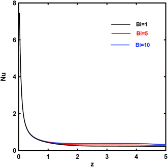 |
| | Fig. 15 Effects of Bi on the local Nusselt number for Da = 10−1, Ec = 5, γ = π/2 and Rk = 5. | |
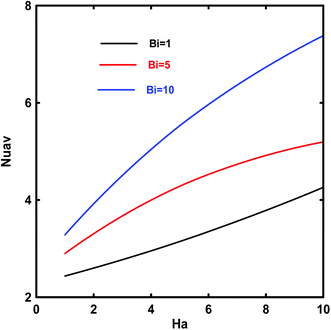 |
| | Fig. 16 Effects of Bi on the average Nusselt number, Nuav, vs. Hartmann number Ha for Kn = 10−3, Da = 10−1, Ec = 5, γ = π/2 and Rk = 5. | |
7.3. Second-law analysis
Integrating the volumetric entropy production into the micro-duct volume, the average entropy generation can be written as:| |
 | (44) |
The local entropy generation, Ns, and average entropy generation, Nsav, are given as a function of different emerging parameters (Fig. 17–23). It is found that all the Ns and Nsav profiles have the same tendency and that two areas are identified: first, a zone with a low gradient of the Ns and Nsav. A second zone with an important gradient. This can be attributed to the increase in temperature gradient as Ha increases. Fig. 17 and 18 illustrate the effect of Kn on the Ns and the Hartmann number on the Nsav as a function of Knudsen number, respectively. As can be seen from these figures that the magnetic field has a great impact on entropy generation. It passes through the duct from a minimum value to a maximum one near the wall. The obtained minimum reached on the axis is due to the smallness of the velocity gradient and because the temperature gradient is nil. This indicates that the FFI dominates the entropy generation rate on the axis. The detected maximum at the wall implies that the velocity slip and temperature jump at the wall have a significant effect on the entropy generation rate. The wall acts as a strong concentrator of irreversibility due to the high value of velocity and temperature gradients occurring at the wall.43
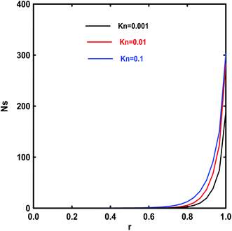 |
| | Fig. 17 Effects of Kn on the local entropy generation rate for Ec = 5, Bi = 1, γ = π/2 and Rk = 5. | |
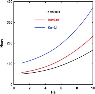 |
| | Fig. 18 Effects of Kn on the average entropy generation, Nsav, vs. Hartmann number Ha for Ec = 5, Da = 10−1, Bi = 1, γ = π/2 and Rk = 5. | |
The effect of the Hartmann number Ha on the entropy generation number Ns (last term of eqn (44)) are plotted in Fig. 19. An increase of this parameter results in an increase of Ns because the presence of the magnetic field creates more entropy in the fluid. Moreover, the entropy generation number is higher near the wall where both temperature and velocity are at their maximum values. This means that the surface acts as a strong source of irreversibility.
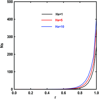 |
| | Fig. 19 Effects of Ha on the local entropy generation rate for Kn = 10−3, Ec = 5, γ = π/2 and Bi = 1. | |
Fig. 20 and 21 show the influence of Ec on Ns and the magnetic field on the average entropy generation Nsav as a function of Ec values, respectively. First of all, it is worth-reminding that the entropy generation is involves of friction, heat transfer and magnetic irreversibility's. Consequently, an increase in magnetic field intensity tends to augment the local Ns (Fig. 20). From this figure, it is clear that the Nsav values present a minimum at low Ec values because the entropy generation due to the fluid friction decreases. This indicates that the Ha has no effect when the viscous dissipation is small. For large values of Ha via an increase of magnetic field intensity, the entropy generation grows significantly with Ec. The highest Nsav is observed near the wall; it has a local maximum. One can perceive that the Ha and viscous dissipation effect raise entropy generation along the longitudinal direction of the flow.
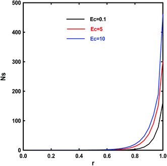 |
| | Fig. 20 Effects of Ec on the local entropy generation rate for Kn = 10−3, Da = 10−1, γ = π/2 and Bi = 1. | |
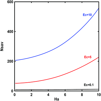 |
| | Fig. 21 Effects of Ec on the average entropy generation, Nsav, vs. Hartmann number Ha for Kn = 10−3, Da = 10−1, Bi = 1, γ = π/2 and Rk = 5. | |
In order to obtain a better understanding of the entropy generation within the LTNE assumption in porous micro duct, we provide the variation of Ns and the effect of increasing magnetic field intensity (Ha) on the local and average entropy generation as a function of Biot number in Fig. 22 and 23. It can be noted that at high Bi, Nsav increases dramatically. The increase in the Bi number indicates a strong internal heat exchange between the fluid and solid phases causing high irreversibility.
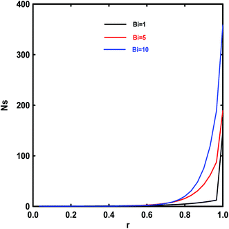 |
| | Fig. 22 Effects of Bi on the local entropy generation rate for Kn = 10−3, Da = 10−1, γ = π/2. | |
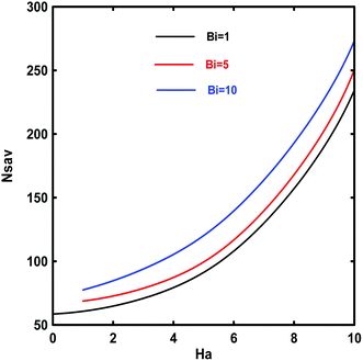 |
| | Fig. 23 Effects of Bi on the average entropy generation, Nsav, vs. Hartmann number Ha for Kn = 10−3, Da = 10−1, Ec = 5, γ = π/2 and Rk = 5. | |
8. Conclusion
In this study, fluid flow, magnetic field, Nusselt number and entropy generation in porous micro duct subjected to oriented magnetic field are numerically investigated for a range of Hartmann number, Knudsen number, Eckert number and Biot number. In the current study, the theoretical model is based on LTNE condition including all terms of viscous dissipation effects. The Modified Lattice Boltzmann Method was used to investigate numerically effects of the emerging parameters. To drive the magnetic field, a new development has been introduced for the simulation of MHD flows with the LBM. Using this new technique, we obtained the magnetic field profiles. Moreover, the Nusselt numbers have asymptotic values depending on the emerging parameters for which the convection and conduction heat transfer are equal (Nu is quasi-constant).
Also, the obtained results of the local and average entropy generation revealed that for all parameters (Kn, Ha, Ec, Bi) the average entropy generation is intensified near the wall of the duct via the highest of temperature and velocity gradients in this region. This is confirmed that the wall represents a concentrator of irreversibility. It is also found that the presence of an external oriented magnetic field has strongly affected the global irreversibility. There is a critical value of Ha for which the global irreversibility is quasi constant depending on the emerging parameters.
Nomenclature
| ai | Specific surface area (m−1) |
| B | Magnetic field (T) |
| Bi | Biot number, Bi = aihiR2/ks |
| Cp | Specific heat capacity at constant pressure, (J kg−1 K−1) |
| cs | Sound speed, (m s−1) |
| Da | Darcy number, Da = K/R2 |
| Ec | Eckert number, Ec = uo2/CfΔTref |
| e | Lattice speed, (m s−1) |
| eα | Discrete velocity, (m s−1) |
| Fε | Forchheimer form coefficient |
| fα | Density distribution function |
| feqα | Equilibrium distribution function of density |
| Fi | Force terme |
| gα | Fluid temperature distribution function |
| geqα | Equilibrium fluid temperature distribution function |
| Ha | Hartmann number,  |
| hi | Interstitial heat transfer coefficient, (W m−2 K−1) |
| hv | Volumetric heat transfer coefficient (W m−3 K−1) |
| hα | Solid temperature distribution function |
| heqα | Equilibrium solid temperature distribution function |
| k | Thermal conductivity, (W m−1 K−1) |
| K | Porous medium permeability, (m2) |
| Kn | Knudsen number |
| Ns | Entropy generation rate |
| Nu | Local Nusselt number |
| Pr | Prandtl number, Pr = μfCpf/kf |
| r,z | Radial and axial coordinates, (m) |
| Re | Reynolds number, Re = Ruoρf/μf |
| Rk | Thermal conductivity ratio, Rk = ks/kf |
| T | Temperature |
| t | Time, (s) |
| u,v | Velocity, (m s−1) |
Greek symbols
| Δz | Lattice step, (m) |
| Δt | Time step, (s) |
| γ | Magnetic field inclination |
| ν | Kinematic viscosity |
| σ | Electrical conductivity |
| ζ | Thermal diffusivity, (m2 s−1) |
| ε | Porosity of porous media |
| μ | Dynamic fluid viscosity, (kg m−1 s−1) |
| λ | Molecular mean free path, (m) |
| ρ | Density, (kg m−3) |
| σv | Tangential momentum accommodation coefficient |
| σT | Thermal accommodation coefficient |
| τ | Dimensionless relaxation time |
| θm | Mixing cup temperature |
| ωα | Weight coefficient |
| β | Specific heat transfer ratio |
| η | Magnetic resistivity |
Subscripts
| e | Effective or equivalent |
| f | Fluid |
| s | Solid. |
References
- B. Buonomo, G. Lauriat, O. Manca and S. Nardini, Int. J. Heat Mass Transfer, 2016, 98, 484 CrossRef.
- M. Dehghan, M. S. Valipour and S. Saedodin, Energy Convers. Manage., 2015, 91, 259 CrossRef.
- S. Qian and H. H. Bau, Mech. Res. Commun., 2009, 36, 10 CrossRef PubMed.
- J. Jang and S. S. Lee, Sens. Actuators, A, 2000, 80, 8489 CrossRef.
- Y. Jian, Int. J. Heat Mass Transfer, 2015, 89, 193 CrossRef.
- C. Das, G. Wang and F. Payne, Sens. Actuators, A, 2013, 201, 43 CrossRef CAS.
- R. Ellahi, Appl. Math. Model., 2013, 37, 1451 CrossRef.
- S. M. Aminossadati, A. Raisi and B. Ghasemi, International Journal of Non-Linear Mechanics, 2011, 46, 1373 CrossRef.
- V. Sofonea and W. G. Frueh, Eur. Phys. J. B, 2001, 20, 141 CrossRef CAS.
- Y. Xuan, M. Ye and Q. Li, Int. J. Heat Mass Transfer, 2005, 48, 2443 CrossRef.
- P. J. Dellar, J. Comput. Phys., 2002, 179, 95 CrossRef CAS.
- P. J. Dellar, J. Stat. Mech.: Theory Exp., 2009, 2009, P06003 Search PubMed.
- C. X. Wang and S. B. Chang, Chin. Phys., 2005, 14, 1398 CrossRef.
- M. J. Pattison, K. N. Premnath, N. B. Morley and M. A. Abdou, Fusion Eng. Des., 2008, 83, 557 CrossRef CAS.
- T. W. Ting, Y. M. Hung and N. Guo, Int. J. Heat Mass Transfer, 2015, 81, 862 CrossRef CAS.
- A. C. Baytas, J. Porous Media, 2007, 10, 261 CrossRef CAS.
- B. Buonomo, O. Manca and G. Lauriat, Int. J. Therm. Sci., 2014, 77, 206 CrossRef.
- M. Torabi, K. Zhang, G. Yang, J. Wang and P. Wu, Energy, 2015, 82, 922 CrossRef.
- T. W. Ting, Y. M. Hung and N. Guo, Energy Convers. Manage., 2015, 105, 731 CrossRef CAS.
- L. J. Betchen and A. G. Straatman, Numer. Heat Transfer, Part B, 2008, 53, 412 CrossRef CAS.
- I. Halliday, L. A. Hammond, C. M. Care, K. Good and A. Stevens, Phys. Rev. E: Stat., Nonlinear, Soft Matter Phys., 2001, 64, 011208 CrossRef CAS PubMed.
- T. Reis and T. N. Phillips, Phys. Rev. E: Stat., Nonlinear, Soft Matter Phys., 2008, 77, 026703 CrossRef CAS PubMed.
- Q. Li, Y. L. He, G. H. Tang and W. Q. Tao, Phys. Rev. E: Stat., Nonlinear, Soft Matter Phys., 2009, 80, 037702 CrossRef CAS PubMed.
- H. Huang and X. Y. Lu, Phys. Rev. E: Stat., Nonlinear, Soft Matter Phys., 2009, 80, 016701 CrossRef PubMed.
- T. Reis and T. N. Phillips, Phys. Rev. E: Stat., Nonlinear, Soft Matter Phys., 2007, 75, 056703 CrossRef CAS PubMed.
- X. D. Niu, C. Shu and Y. T. Chew, Int. J. Mod. Phys. C, 2003, 14, 785 CrossRef.
- J. G. Zhou, Phys. Rev. E: Stat., Nonlinear, Soft Matter Phys., 2011, 84, 036704 CrossRef PubMed.
- H. R. Ashorynejad, A. A. Mohamad and M. Sheikholeslami, Int. J. Therm. Sci., 2013, 64, 240 CrossRef CAS.
- A. A. V. Servati, K. Javaherdeh and H. R. Ashorynejad, Adv. Powder Technol., 2014, 25, 666 CrossRef.
- A. K. Husseina, H. R. Ashorynejadb, M. Shikholeslamib and S. Sivasankaran, Nucl. Eng. Des., 2014, 268, 10 CrossRef.
- D. Gao, Z. Chen and L. Chen, Int. J. Heat Mass Transfer, 2014, 70, 979 CrossRef.
- Q. Liu, Y. L. He and Q. Li, J. Comput. Phys., 2014, arXiv:1409.5929 Search PubMed.
- Y. Shi, T. S. Zhao and Z. L. Guo, Phys. Rev. E: Stat., Nonlinear, Soft Matter Phys., 2004, 70, 066310 CrossRef PubMed.
- Y. Mahmoudi, Int. J. Heat Mass Transfer, 2015, 85, 524 CrossRef.
- S. B. Celik, A thesis submitted to the graduate school of natural and applied sciences of Middle East technical university, 2012 Search PubMed.
- Q. Zou and X. He, Phys. Fluids, 1997, 6, 1591 CrossRef.
- A. Mohamad, Lattice Boltzmann Method Fundamentals And Engineering Applications with Computer Codes, Schulich School of Engineering, the University of Calgary, Alberta, Canada, 2011, pp. 2–31, ISBN 978-0-9783253-0-5 Search PubMed.
- F. Rong, Z. Guo, Z. Chai and B. Shi, Int. J. Heat Mass Transfer, 2010, 53, 5519 CrossRef.
- F. Selimefendigil, H. F. Öztop and A. J. Chamkha, J. Magn. Magn. Mater., 2016, 406, 266 CrossRef CAS.
- H. Dhahri, K. Slimi and S. Ben Nasrallah, Comput. Therm. Sci., 2010, 2, 381 CrossRef.
- O. M. Haddad, M. A. Al-Nimr and J. Sh. Al-Omary, Transp. Porous Media, 2007, 67, 453 CrossRef.
- O. M. Haddad, M. A. Al-Nimr and M. S. Sari, Forced convection gaseous slip flow in circular porous micro-channels, Transp. Porous Media, 2007, 70, 167 CrossRef CAS.
- H. Dhahri, A. Boughamoura and S. BenNasrallah, J. Porous Media, 2013, 16, 69 CrossRef.
|
| This journal is © The Royal Society of Chemistry 2017 |
Click here to see how this site uses Cookies. View our privacy policy here.  Open Access Article
 *,
Abir Yahya,
Bayssain Amami and
Hacen Dhahri


 and R*k = (1 − ε)ks/εkf


 and R*k = (1 − ε)ks/εkf


