DOI:
10.1039/C7RA04036A
(Paper)
RSC Adv., 2017,
7, 30687-30698
Exploration of polyepoxysuccinic acid as a novel draw solution in the forward osmosis process
Received
9th April 2017
, Accepted 31st May 2017
First published on 14th June 2017
Abstract
Polyepoxysuccinic acid (PESA) is a green corrosion scale inhibitor. When PESA is used for wastewater desalination in the forward osmosis (FO) process, the diluted PESA solution could be used for cooling systems. In our investigation, the effects of membrane orientation, temperature and flow rate on FO performance are studied using PESA as a draw solute. The results show that the effect of temperature on water flux is obvious, but the water flux increase is higher from 25 °C to 35 °C than that from 35 °C to 45 °C. Compared to the FO mode, the water flux increases faster in the pressure-retarded osmosis mode (PRO mode) at high flow rate due to the reduction of concentrative internal concentration polarization (CICP). Compared with polyaspartic acid (PASP) and NaCl, the water flux of PESA is the lowest under the same conditions. However, PESA has the lowest specific reverse solute flux (Js/Jw) at both membrane orientations. For example in the FO mode this value is 0.46 g L−1, whereas that of NaCl and PASP is 1.12 and 0.74 g L−1, respectively. This means that PESA has lower loss to the feed side than NaCl and PASP in the FO process, which greatly reduces the replenishment cost of the draw solute. The use of PESA as the draw solute in the FO process to treat dyeing water has the advantages of stable water flux (within 20 min), high dye rejection (nearly 1) and reversible membrane fouling (restored to 97%). The nanofiltration (NF) process indicates the good performance of PESA recovery with a high specific water flux (0.94 LMH per bar) and rejection rate (97.8%). Thus, the overall performance of PESA demonstrates that it is a promising draw solute.
1. Introduction
Currently, fresh water resources cannot meet the demand of the population, industry and economy due to their rapid growth. Thus, scientists are conducting much research on the desalination of wastewater.1,2 Among the various technologies, membrane separation is one of the most outstanding.3 Reverse osmosis (RO) is the most widely applied desalination technology in various membrane processes.4 However, there are still some drawbacks of RO, including serious concentration polarization, irreversible membrane fouling and the discharge of concentrated brine.5 These issues have led scientists to explore alternative technologies to produce clean water.
Forward osmosis (FO) is a recent emerging technology for wastewater treatment.6–8 In FO, pure water permeates from the feed solution (FS) to the draw solution (DS) through a semi-permeable membrane due to osmotic pressure differences.9 The outstanding advantages of FO include high water flux, low energy requirement, high salt rejection and low membrane fouling.10,11 Currently, FO is widely applied in brackish water/seawater desalination,12–14 sludge dewatering,15–17 and pharmaceutical factory.18 However, its development is still hampered by two key factors, which are an ideal FO membrane and efficient draw solution. An excellent FO membrane should have the following properties: high water flux, high rejection of solutes and good anti fouling performance. Good draw solutes should have the features of high solubility, non-toxicity, low reverse solute flux, compatibility with the membrane, and easy recovery.19–21 Compared to the rapid development and nearly commercialization of FO membranes,22–24 finding an appropriate draw solute becomes critical.
Various draw solutions have been studied over the last few decades. The conventional inorganic salts such as NaCl generate a high water flux, but serious reverse solute leakage and the difficulty of draw solution recovery increase the operational costs.25 Ammonium bicarbonate produces high osmotic pressure and is easily recycled by distillation at around 60 °C, but NH3 is difficult to remove to a drinkable level.12,26 It was reported that magnetic nanoparticles as draw solutions make it easier to recover draw solutes. However, particle aggregation during recycling is a problem.8 Hydrogels were found to be environmentally friendly when used as draw solutes. However, they have a poor water recovery rate and are unsuitable for practical application.27 Furthermore, several inorganic salts that can also serve as fertilizers were used as draw solutes. The diluted draw solutes can be used for agricultural irrigation, therefore the recovery of these solutes is unnecessary. However, the final diluted solutes are usually higher than the acceptable level for fertilization, and thus require a large amount of water to reduce their concentrations.4,28 In a previous paper, a novel bulky hydroacid complex Na4[Co(C6H4O7)2]·2H2O(Na–Co-CA) was synthesized as the draw solute in FO, which showed high water flux and high rejection to remove heavy metal ions from wastewater.29 However, it is still necessary to explore more suitable draw solutes.
Recently, polyelectrolytes as draw solutions have been gaining much interest. They can dissolve well in water, which guarantees high osmotic pressure with high water flux. Besides, polyelectrolytes with expanded structures reduce reverse solute leakage and make the recovery easier. Long et al.30 used a one-step Mannich-like reaction to synthesize a series of organic phosphonate salts (OPSs) and applied them as draw solutes in FO. Compared to NaCl, they had a higher water flux and lower reverse solute flux. Nearly 92% rejection was achieved using a nanofiltration system to recover the diluted OPS solution. Ge et al.3 studied different molecular weights of sodium salts of polyacrylic acid (PAA–Na) as draw solutes. They proved that the solution with the lowest molecular weight generated the highest water flux due to its low viscosity and high dissociation. Gwak et al.31 investigated polyaspartic acid (PASP) as a draw solution in the FO process. Their results showed that PASP had a low reverse solute flux and comparable water flux. Besides, the reverse PASP solutes had a significant effect on reducing inorganic scaling. Wang et al.32 used carboxyethyl amine sodium salts (CASSs) as novel draw solutes in FO. When CASSs were used as draw solutes, a relatively higher water flux and lower reverse solute flux were achieved due to their relative high osmotic pressure and large molecule sizes.
The polyelectrolyte polyepoxysuccinic acid (PESA) is a green corrosion scale inhibitor, which has been used in many cooling water systems and shows excellent scale performance. When PESA is used for wastewater desalination in the FO process, the diluted PESA solution could be used in cooling systems, which not only saves water resources but also avoids the running cost of the subsequent recovery. In this work, PESA was chosen as the draw solution. It has significantly large molecular, good water soluble, non-toxic, and biodegradable features. This investigation is mainly comprised of four sections: (1) studying the chemical and physical properties of PESA. (2) Comparing its FO performance under different membrane orientations with NaCl and PASP draw agents. (3) Investigating its performance as a draw solution in the FO process under different concentrations, temperatures, cross flow rates, and membrane orientations using deionized (DI) water as the feed solution. (4) Studying the feasibility and applicability of using PESA as a draw solution for dyeing wastewater treatment and brackish water desalination. Additionally, the diluted PESA solution could be used in many cooling water systems. Besides, there are many processes such as membrane distillation, ultrafiltration and nanofiltration for regeneration of the PESA solution.33,34 It is envisioned that this study may provide fundamentals for the development of novel draw solutions for the FO process.
2. Materials and methods
2.1 Forward osmosis membrane
The membrane used in our study was a homemade polyamide thin film composite (TFC) FO membrane, which possesses various advantages such as high water flux and high salt rejection. However, its high reverse solute flux is a drawback. The physical and chemical properties of the membrane are presented in Table 1.35,36 The contact angle of the TFC-FO membrane was less than 70°, which indicates that the membrane is hydrophobic. Contact angle was measured using a contact angle goniometer (JC2000C Contact Angle Meter, Shanghai Zhongchen Experiment Equipments Co. Ltd., China).
Table 1 The physical and chemical properties of the TFC-FO membrane
| Sample |
Active layer material |
Contact angle(°) |
Zeta potential (mV) at active layer |
Operating pH |
| Active layer |
Support layer |
| TFC |
Polyamide |
57 |
65 |
−28.75 |
2–11 |
There are two different membrane orientations applied in the FO process. One orientation is described as the FO mode, in which the support layer faces the DS and the active layer faces the FS. The other orientation is called the pressure-retarded osmosis mode (PRO mode), in which the active layer faces the DS and the mechanical support layer faces the FS.
In order to have a clear observation of the TFC-FO membrane, micrographs of the membrane were obtained using a scanning electron microscope (HITACHI S-520). The active layer, support layer, and cross-section micrographs are shown in Fig. 1. The cross-section sample was cracked under flash freezing in liquid nitrogen. All the membrane samples were dried in a vacuum oven overnight.
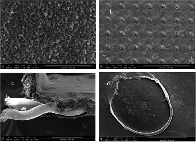 |
| | Fig. 1 SEM images of the TFC-FO membrane: (a) general view of the active layer, (b) general view of the support layer, (c) cross-section and (d) hole in the support layer. | |
2.2 Feed and draw solution
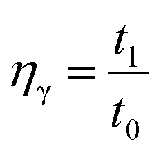
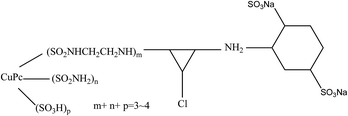
In the basic FO performance tests, deionized (DI) water was used as the feed solution. For the wastewater treatment experiments, dyeing wastewater and brackish water were used as the feed solutions. Reactive blue dye (K-GL) and disperse yellow (RGFL) were chosen as representatives of dyeing wastewater, which were obtained from the Jinan no. 2 Dyeing Mill, China. The name, maximum absorbance wavelength, pH, zeta potential and molecular structure are shown in Table 2. The synthetic dyeing wastewater was prepared by adding 0.2 g dye to 1 L DI water and the concentration was similar to that of the actual wastewater. The synthetic brackish water (0.3 M NaCl) was prepared by adding 17.55 g NaCl salt to 1 L DI water. NaCl was obtained from Sinopharm Chemical Reagent Co., Ltd (Shanghai). The PESA draw solution was obtained from the Shandong Xintai Water Treatment Technology Co., Ltd and Table 3 shows its physicochemical characteristics. PESA is colorless or transparent amber liquid with a relatively large molecular weight ranging from 400 to 1500. The osmotic pressure of PESA was measured using a freezing point osmometer (Germany Löser). The viscosities of PESA under different concentrations and temperatures were measured using an Ubbelohde viscometer (1835 0.3–0.4 mm, Shanghai Bolea Instrument & Equipment Co., Ltd). The relative viscosity of PESA, ηγ, compared to DI water is calculated using the equation| |
 | (1) |
where, t1 and t0 are the elution time of the polyelectrolyte solution and DI water, respectively.
Table 2 Characteristics of the dyes
| Name |
pH |
Zeta potential (mV) |
Wave length (nm) |
Molecular structure |
| Reactive blue (K-GL) |
6.0 |
−35.6 |
598 |
 |
| Disperse yellow (RGFL) |
5.4 |
−55.7 |
445 |
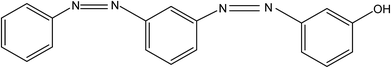 |
Table 3 The physical and chemical properties of PESA
| Appearance (25 °C) |
Colorless or transparent amber liquid |
Density (20 °C) g cm−3 |
1.28 |
| Molecular formula |
HO(C4H2O5M2)n·H |
pH (25 °C, 1% solution) |
9.0–12.0 |
| Molecular weight |
400–1500 |
Solid content% |
40 |
2.3 Forward osmosis system
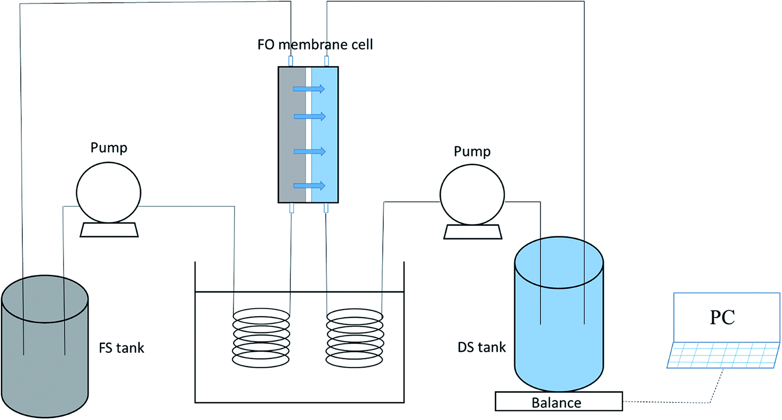
Fig. 2 displays a schematic drawing of the FO setup used in our studies, which is similar to that in previous studies.33,37 The effective membrane area of the lab-scale membrane unit was 20.0 cm2 (7.7 cm length, 2.6 cm width and 0.3 cm depth). The feed and draw solutions were circulated by two pumps and flowed concurrently at different flow rates. A water bath controlled by a temperature control unit was used to adjust the temperatures of both the feed and draw solutions. A weight balance (Satorius Weighing Technology GmbH, Gottingen, Germany) was used to record the weight of the draw solution for the computation of water flux. The original volumes of both the feed and draw solutions were 1 L in our experiments.
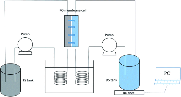 |
| | Fig. 2 Schematic diagram of the lab-scale FO experimental set-up. | |
2.4 Measurement of water flux and reverse solute flux
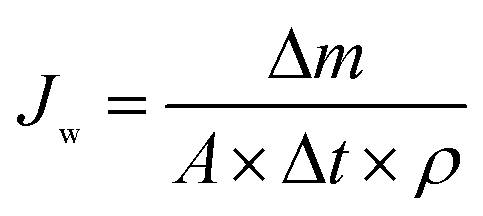
2.4.1 Water flux. Water flux is calculated using the following equation:| |
 | (2) |
where, Jw is the water flux in the experiments, L (m−2 h−1) (LMH); Δm is the measured weight interval for the water that permeated from the FS to the DS; A is the effective area of the TFC-FO membrane; Δt is the measuring time interval and ρ is the density of water.
2.4.2 Reverse salt flux. Reverse salt flux is calculated using the following equation:| |
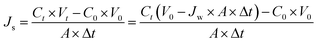 | (3) |
where, Js is the reverse salt flux in the FO process, g (m−2 h−1) (gMH); A is the effective area of the TFC-FO membrane; Δt is the time interval; V0 and Vt are the initial and final volumes of the FS, respectively; and C0 and Ct are the initial and final salt concentrations of the FS, respectively.
2.5 Nanofiltration process
NF experiments were conducted using a lab-scale cross-flow filtration unit (FlowMem-CF042SS, USA). The commercial NF membrane NF-90 with an effective filtration area of 40.5 cm2 was used in our experiments. More details about the membrane are shown in Table 4. The feed solution (PESA solution) with a concentration of 0.03 g mL−1 was filtrated at the operating pressure of 20 bar and temperature of 25 ± 1 °C. Before each test, a new membrane was soaked in DI water overnight. The water flux was calculated using eqn (2). The solute rejection is calculated by the following equation:| |
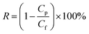 | (4) |
where, R is the solute rejection and Cp and Cf are the solute concentrations of the permeate and feed water, respectively.
Table 4 Properties of commercial NF membrane
| Property |
NF-90 |
| Pure water permeability (LMH per bar) |
6.48 |
| Top layer material |
Polyamide |
| Feed water pH range |
2–11 |
| Maximum applied pressure (psi) |
600 |
3. Results and discussion
3.1 Properties of PESA
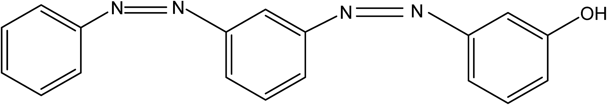
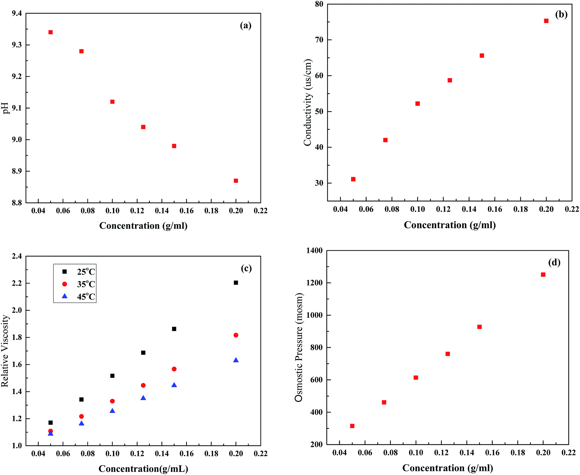
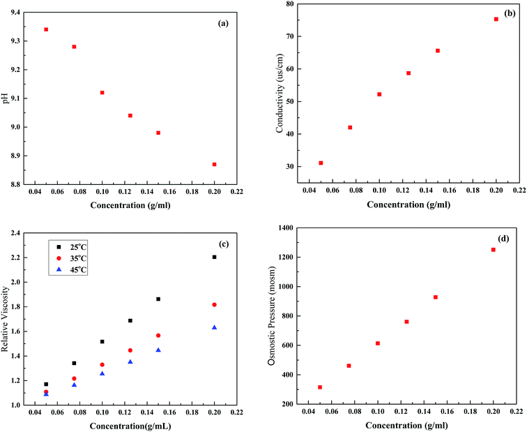
PESA has been proven to have large molecular, good water soluble, non-toxic, and biodegradable features, and its chemical structure is shown in Fig. 3. It can be seen that PESA has an expanded structure, which contributes to a low reverse solute flux and easy solute regeneration in the post treatment. Fig. 4 shows the PESA properties at different concentrations, including pH, conductivity, viscosity, and osmotic pressure. It is shown that the pH of PESA ranges from 9.34 (0.5 g mL−1) to 8.87 (2 g mL−1) and it decreases with concentration (Fig. 4(a)). The recommended operational pH range of the TFC-FO membrane is from 2.0 to 12.0.38 Thus, the membrane will not undergo structural changes in the FO process. As shown in Fig. 4(b), the conductivity of PESA is directly proportional to concentration, which is in agreement with the previous study using organic salts as the DS.39 This phenomenon shows that PESA dissociates well in water, which is enhanced with concentration. The electrical conductivity of PESA may be derived from the dissociation of ions and outer coordination spheres. The relative viscosity of PESA is shown in Fig. 4(c). The results show that the viscosity increases with an increase in concentration. At the same concentration, the PESA solution at a higher temperature exhibits a smaller value of ηγ. A high viscosity of DS has a bad effect on fluid flow through the membrane and results in severe internal polarization concentration.14 Compared to the polyelectrolyte PAA (2–3 at a concentration of 0.12 g mL−1), PESA (∼1.8 at a concentration of 0.15 g mL−1) exhibits a smaller relative viscosity, which shows its advantages as a draw solute.3 Fig. 4(d) shows the osmotic pressure of PESA at different concentrations. It can be seen that the osmotic pressure has an almost linear correlation with concentration from 0.5 to 2 g mL−1. High osmotic pressure is associated with high conductivity, which is in agreement with Fig. 4(b).
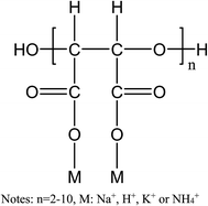 |
| | Fig. 3 Chemical structure of PESA. | |
 |
| | Fig. 4 Characteristics of the PESA draw solution. (a) pH, (b) conductivity, (c) relative viscosity and (d) osmotic pressure. | |
PESA is a green corrosion scale inhibitor which has been used in many cooling water systems and shows excellent scale performance.40 Generally, the concentration of PESA in cooling systems varies from a few milligrams per liter to a few tens of milligrams per liter. Thus, it is necessary to add pure water to the diluted PESA solution to adjust its concentration. Besides, PESA has been proven to be suitable for high temperature and high pH conditions, thus it can be used without adjusting the pH unless there is a special need.41–43 Furthermore, there are many processes such as membrane distillation, ultrafiltration, and nanofiltration for the regeneration of the PESA solution.33,34 The overall properties of PESA indicate its great potential as an alternative draw solution.
3.2 Basic FO performance
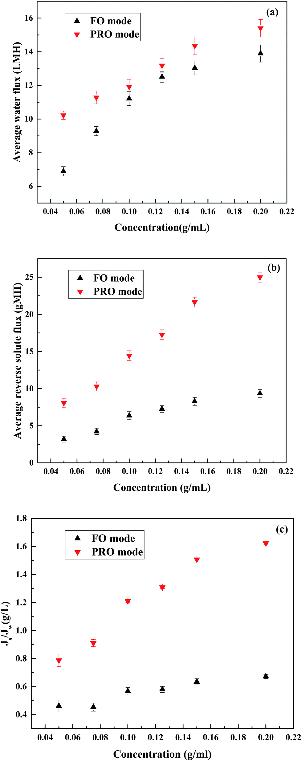
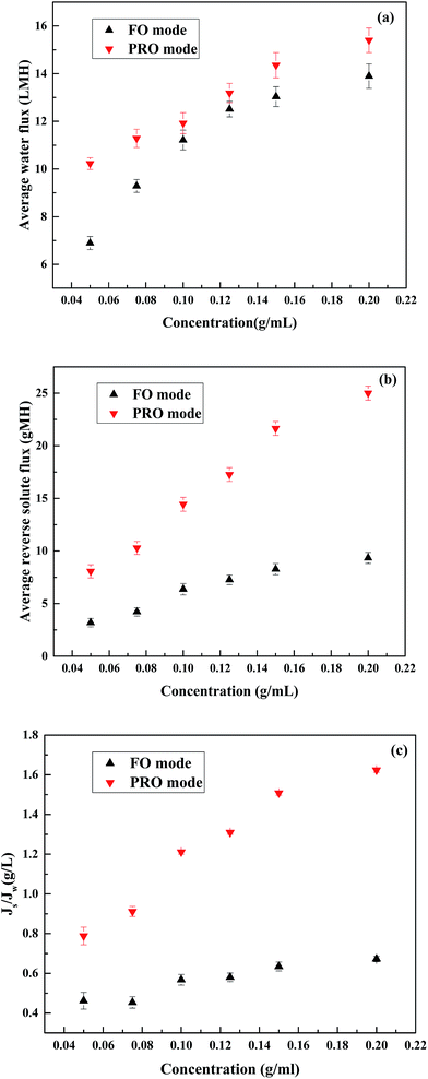
In order to confirm the feasibility of using PESA as a draw solution in the FO process, the basic FO performance including water flux and reverse solute flux of PESA was firstly measured. Fig. 5 represents the effect of PESA concentration on water flux and reverse solute flux using DI water as the feed solution on the performance of the FO process. The temperature was 25 °C and the cross flow rate was 17 cm s−1. As shown in Fig. 5(a), in both the PRO and FO modes, the water flux increased trend when the PESA concentration increased from 0.05 to 0.2 g mL−1. A higher draw solution concentration could generate a larger osmotic driving force, which leads to a higher water flux across the membrane.44 However, the increase in water flux was not directly proportional to PESA concentration, which could be explained by concentration polarization. The higher concentration of PESA reduced its diffusivity, thus leading to serious concentration polarization, which resulted in a non-linear relationship between concentration and water flux. Besides, it can be seen that the pH of PESA decreases with an increase in concentration (Fig. 4(a)). PESA ionizes when it is dissolved in water, and the ionization of PESA in water increases with pH,45 which influences the osmotic pressure and leads to a non-linear variation in water flux. Similarly, as shown in Fig. 5(b), the reverse solute flux also increased when the PESA concentration increased from 0.05 to 0.2 g mL−1 following the same trend as that of water flux. The maximum water flux was considered as 15.40 LMH at the concentration of 0.2 g mL−1 under the PRO mode and the minimum reverse solute flux was recorded as 3.19 gMH at the concentration of 0.05 g mL−1 under the FO mode. The specific reverse solute flux (Js/Jw) refers to the ratio of reverse solute flux to water flux, which is used as an indicator of DS loss per volume of water permeation in the FO process. Fig. 5(c) shows the specific reverse solute flux (Js/Jw) in terms of PESA concentration in both the PRO and FO modes, where it is found that the specific reverse solute flux increases independently of concentration under both membrane orientations. It can be seen that all the Js/Jw vales are higher than that in previous studies3,31 which may be due to differences in the membrane structure because the membranes used in our studies were homemade membranes.
 |
| | Fig. 5 Effect of PESA draw solution concentration on FO performance at different membrane orientations. (a) Water flux, (b) reverse solute flux and (c) specific reverse solute flux at 25 °C and 17 cm s−1. | |
3.3 Comparison of PESA, PASP and NaCl
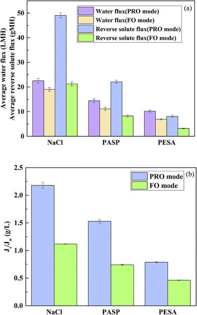
To compare the FO performance of PESA, NaCl (an extensively used inorganic salt) and PASP (a recently reported polyelectrolyte), FO experiments were conducted using 0.05 g mL−1 as the model DS concentration and DI water as the feed solution at a temperature of 25 °C and cross flow rate of 17 cm s−1. The osmotic pressure of 0.05 g mL−1 NaCl, PASP and PESA was 1437, 652 and 315 mOsm, respectively. 0.05 g mL−1 PESA had a lower osmotic pressure than PASP, and both of them were less than NaCl. As observed in Fig. 6(a), the water flux difference followed the order NaCl > PASP > PESA. Although NaCl had an obviously higher water flux compared to that of PASP and PESA, its large reverse solute flux is an issue, especially in the PRO mode. PASP had higher water flux than PESA which could be simply explained by the osmotic pressure difference between these two solutions.46 Although the same concentration was used, the osmotic pressure of 0.05 g mL−1 PASP (652 mOsm) was higher than that of 0.05 g mL−1 PESA (315 mOsm), whereas PESA had an obviously lower reverse solute flux than that of PASP and NaCl. NaCl had the smallest molecular weight and thus the largest reverse solute flux. Furthermore, the zeta potential of PESA and PASP was measured. The zeta potential of PESA and PASP was −49.1 and −14.6 mV, respectively. Due to the stronger mutual repulsion of the same charge, the TFC membrane (zeta potential of −28.75 mV, Table 1) is more repulsive to PESA. Thus, the reverse solute flux of PESA is much lower than that of PASP. The loss of draw solutes by reverse diffusion leads to an increase in operational cost due to the replenishment of additional draw solutes, but it should be noted that a high water flux always occurs with a high reverse solute flux. Thus, we need to consider the specific reverse solute flux. As shown in Fig. 6(b), PESA had the lowest Js/Jw value at both membrane orientations, for example in the FO mode the Js/Jw value of PESA was 0.46 g L−1, whereas that of NaCl and PASP was recorded as 1.12 and 0.74 g L−1, respectively. These results indicate that PESA has lower loss to the feed side than NaCl and PASP for each liter of water produced in the FO process, which would greatly reduce the replenishment cost of the PESA draw solute.
 |
| | Fig. 6 Performance comparison of PESA (0.05 g mL−1) with two draw solutions, specifically NaCl (0.05 g mL−1) and PASP (0.05 g mL−1). (a) Water flux and reverse solute flux and (b) specific reverse solute flux, at 25 °C and 17 cm s−1. | |
3.4 Effect of temperature and cross flow rate on water flux
In order to determine the influence of temperature and cross flow rate on water flux using PESA as DS, FO experiments were conducted under different membrane orientations, temperatures and cross flow rates.
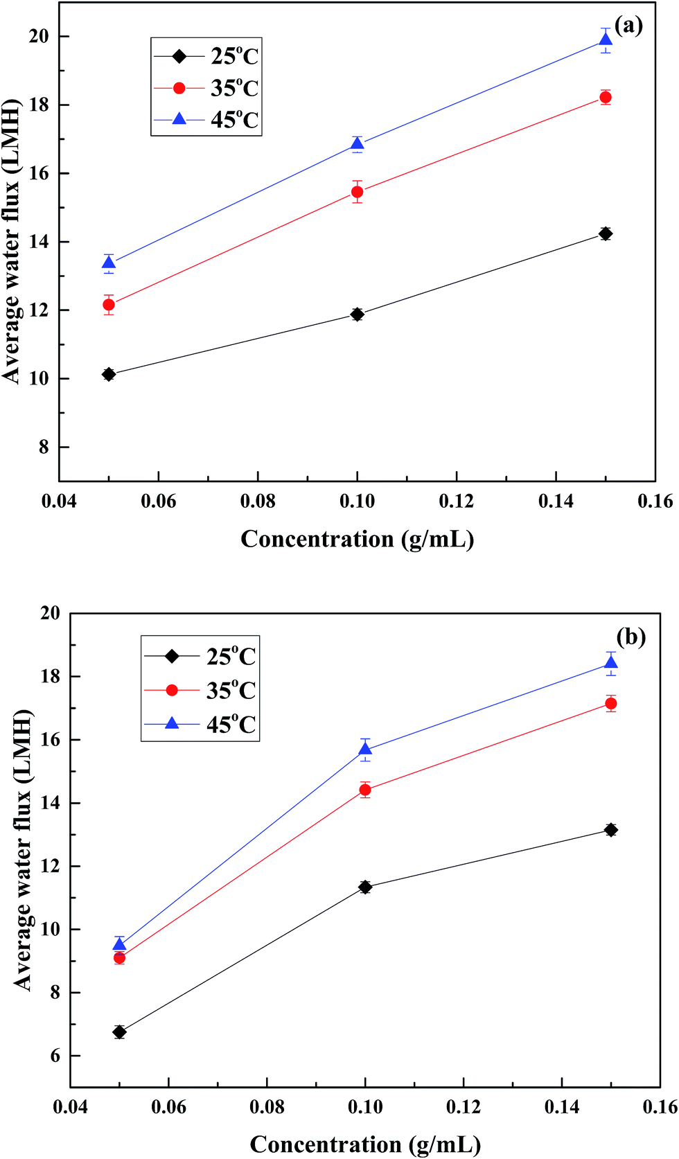
3.4.1 Effect of temperature on water flux. To evaluate the influence of temperature in the FO process, FO experiments were conducted at different draw solution concentrations (0.05, 0.1 and 0.15 g mL−1), temperatures (25 °C, 35 °C and 45 °C) and membrane orientations (PRO and FO modes) and the cross flow rate was maintained at 17 cm s−1. Fig. 7 shows the variation in water flux with temperature during operation in the PRO and FO modes. As the temperature increased from room temperature to 45 °C, the water flux also increased. This is mainly due to the increased osmotic pressure and diffusion coefficient, and decreased viscosity of the solutions at high temperature, which can be seen in Fig. 4. For the feed side, the enhanced temperature increased the diffusion coefficient and at the same time decreased the viscosity, which resulted in an increase in the water-transporting kinetics. For the draw side, the enhanced temperature increased the osmotic pressure, which led to an improvement in the driving force across the membrane. Besides, the dissociation of PESA should be considered since PESA ionizes when it is dissolved in water. The ionization of PESA in water increases with temperature, which will influence the osmotic pressure and cause the water flux to increase. Specifically, a considerable increase in water flux was observed when the temperature increased from 25 °C to 35 °C (in both PRO and FO modes). However, a slight increase in water flux was observed for the increase in temperature from 35 °C to 45 °C. The variation tendency was almost the same as that of the relative viscosity presented in Fig. 4. It can be seen that the relative viscosity decreases obviously with temperature from 25 °C to 35 °C compared to the temperature increase from 35 °C to 45 °C. Increasing the temperature of the draw solute could lead to a decrease in its viscosity and an increase in its diffusion coefficient, which would enhance mass transfer and reduce dilutive external concentration polarization, thus leading to an increase in water flux.47,48 This indicates that a small increase in room temperature can result in a considerable water flux. High temperatures can generate high water flux, but this is not economical. It can be also seen that the increase in water flux was not linear with the increase in concentration of PESA, especially in the FO mode. From Fig. 7(b), a considerable increase in water flux was observed for the increase in concentration from 0.05 to 0.1 g mL−1, whereas a slight increase in water flux was observed from 0.1 to 0.15 g mL−1. This is due to the sudden increase in viscosity between these two concentrations which had a dominating influence compared to the small increase in osmotic pressure.49
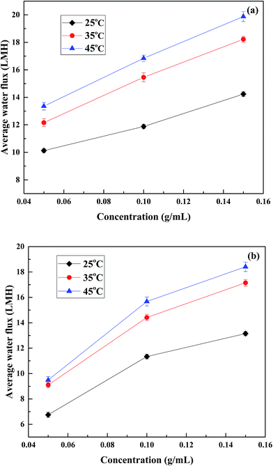 |
| | Fig. 7 Effect of temperature on water flux of different concentrations of PESA. (a) PRO mode and (b) FO mode at the cross velocity of 17 cm s−1. | |
Thus, it can be concluded that water permeation is susceptible to temperature. In both PRO and FO modes, the increase in water flux from 25 °C to 35 °C was more obvious than that from 35 °C to 45 °C. Therefore, in terms of economy and utility, it is best to control the temperature below 35 °C when using PESA as the draw solution in the FO process.
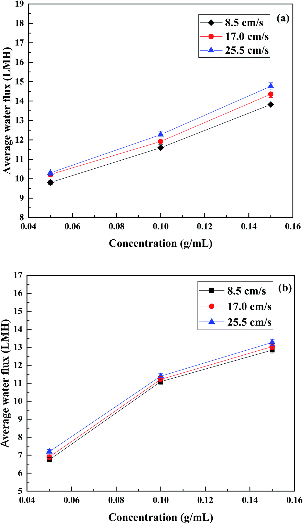
3.4.2 Effect of cross flow rate on water flux. To determine whether the cross flow rate of the PESA draw solution and feed solution could improve the water flux, a wide range of velocities (8.5, 17 and 25.5 cm s−1) was used in the FO operation, where the temperature was maintained at 25 °C and three different DS concentrations (0.05, 0.1 and 0.15 g mL−1) were chosen. The results in Fig. 8 show that the water flux at high velocities was higher than that at low cross velocities. However, the water flux difference in the FO mode was minor at the three cross flow rates which was different from that in a previous study.37 In the case of 0.05 g mL−1 in the FO mode, the water flux was about 6.74 LMH at the cross flow velocity of 8.5 cm s−1, and the flux value was only 2.22% and 6.68% higher at a cross flow velocity of 17 and 25.5 cm s−1, respectively. For the concentrations of 0.1 and 0.15 g mL−1, the water flux increased by 1.17% and 2.79% (0.1 g mL−1) and 1.48% and 3.27% (0.15 g mL−1) at a cross flow velocity of 17 and 25.5 cm s−1 compared to that at 8.5 cm s−1. In the FO mode, the membrane active layer faces the FS and the support layer faces the DS, which lead to concentrative external concentration polarization (CECP) and dilutive internal concentration polarization (DICP). For the feed side, the enhanced cross flow rate increased turbulent flow as a result the weakened CECP,48 whereas in the draw side, the high cross flow rate increased turbulent flow between the bulk solution and the membrane surface leading to back diffusion of the salts to the bulk solution.50 Thus, DICP in the support layer was alleviated. The overall results led to a slight water flux difference under the FO mode.
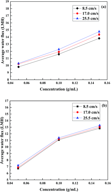 |
| | Fig. 8 Effect of cross flow velocity on water flux of different concentrations of PESA. (a) PRO mode and (b) FO mode at the temperature of 25 °C. | |
In the PRO mode, the water flux difference at three flow rates was slightly more obvious compared to that in the FO mode. In the case of 0.05 g mL−1, the water flux was about 9.81 LMH at the cross flow velocity of 8.5 cm s−1, and the flux value was 4.18% and 4.99% higher at a cross flow velocity of 17 and 25.5 cm s−1, respectively. For the concentrations of 0.1 and 0.15 g mL−1, the water flux increased by 2.85% and 5.87% (0.1 g mL−1) and 3.84% and 6.81% (0.15 g mL−1) at a cross flow velocity of 17 and 25.5 cm s−1 compared to 8.5 cm s−1. In PRO mode, the active layer faces the DS and the support faces the FS, which lead to dilutive external concentration polarization (DECP) and concentrative internal concentration polarization (CICP). For the draw side, similarly to the feed side in the FO mode, the increased cross flow rate reduced DECP. In the feed side, increasing the flow rate increased turbulent flow and promoted back diffusion of the salts from the porous medium to the bulk feed solution. Thus, the driving force across the membrane increased which resulted in a higher water flux.50,51 Indeed, the increased water flux is attributed to the reduction of CICP. Thus, a high flow rate in the PRO mode is preferable when using PESA as the draw solute.
3.5 Application of PESA in FO for wastewater treatment
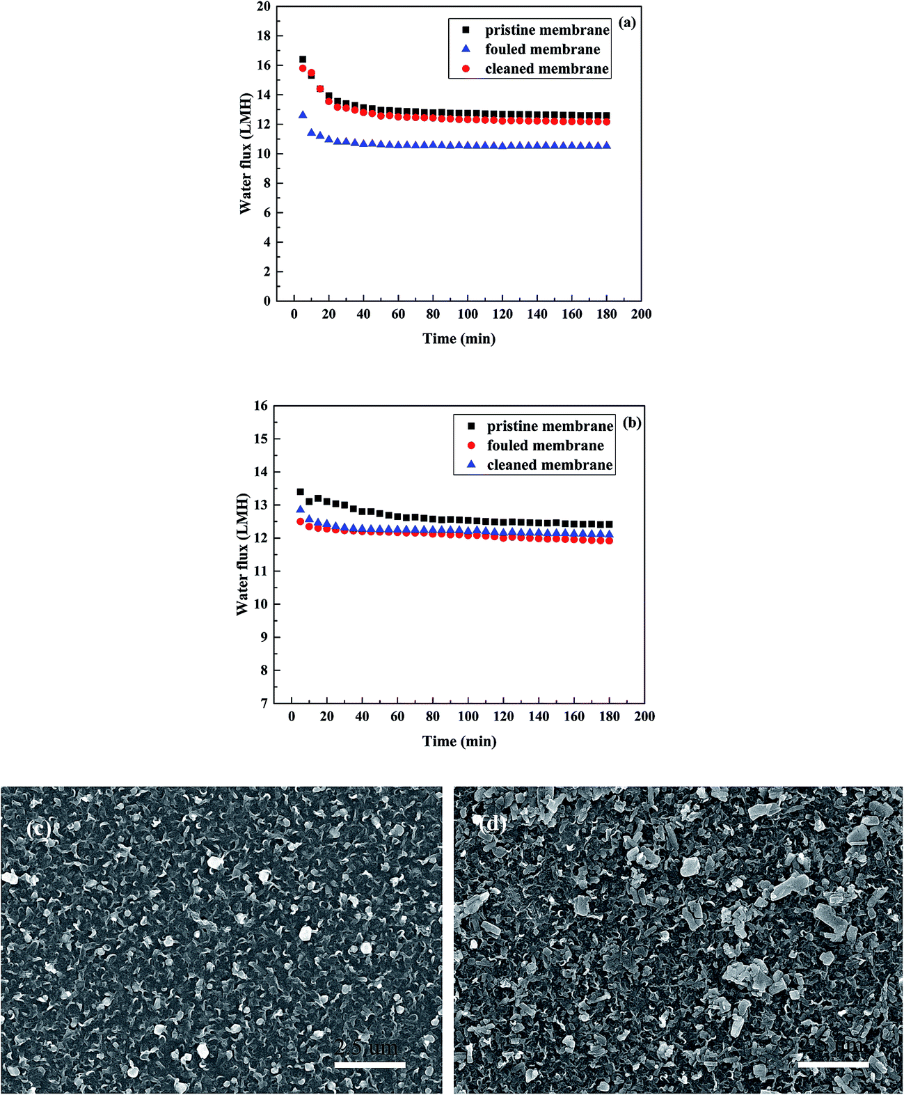
3.5.1 Dyeing wastewater treatment. The feasibility of using FO to treat dyeing wastewater was studied using synthetic dyeing water as the FS and PESA solution at a concentration of 0.15 g mL−1 as the DS under the FO mode with the temperature of 25 °C and flow rate of 17 cm s−1 and the results are shown in Fig. 9. Fig. 9(a) and (b) represent K-GL and RGFL, respectively. It can be seen (Fig. 9(a)) that the water flux of PESA achieved balance in 20 min, which indicates that the water flux of PESA as the DS to treat dyeing wastewater is fairly stable. An ultraviolet visible spectrophotometer (UV254, Puxi General Instrument Co. Ltd., Beijing, China) was used to detect the dye content in DS, and the results show that the content of dye was zero. This indicates that the dye rejection of the TFC-FO membrane was almost as high as 1. The fouled membrane was cleaned by freshwater for 1 h and then used to test water flux under the same conditions. As shown in Fig. 9, the water flux of the cleaned membrane (restored to about 97%) was almost the same as that of the pristine membrane. These results show that the membrane fouling in the process is reversible, and the water flux well recovered after flushing the membrane with freshwater. A similar trend was obtained in Fig. 9(b) using RGFL as the feed solution. The water flux was stable and the water flux of the cleaned membrane was restored to about 97% after cleaning with freshwater for 1 h. However, when the UV254 was used to detect the dye content in the diluted DS, the measured absorbance value was 0.125, which is due to the small molecular weight and good diffusion properties of the disperse dyes. However, according to the standard curve of Disperse yellow at different concentrations, the concentration of RGFL in DS was 14 mg L−1 which is almost negligible.32 In order to have a clear observation of the membrane fouling, the SEM images of the cake layer are shown in Fig. 9. Fig. 9(c) and (d) display the images of K-GL and RGFL, respectively. It can be seen that K-GL is more compact and RGFL is more dispersed on the membrane. This due to the fact that RGFL has a lower molecular weight than K-GL, which leads to the dispersed state on the membrane. The overall performances show the advantages of using PESA as the DS in the FO process to treat dyeing water with stable water flux, high dye rejection and reversible membrane fouling.
 |
| | Fig. 9 Water flux variation using PESA (0.15 g mL−1) as the DS in the FO process to treat dyeing wastewater. (a) Reactive blue and (b) disperse yellow at the temperature of 25 °C and flow rate of 17 cm s−1 in the FO mode. SEM images of the cake layer of (c) K-GL and (d) the RGFL. | |
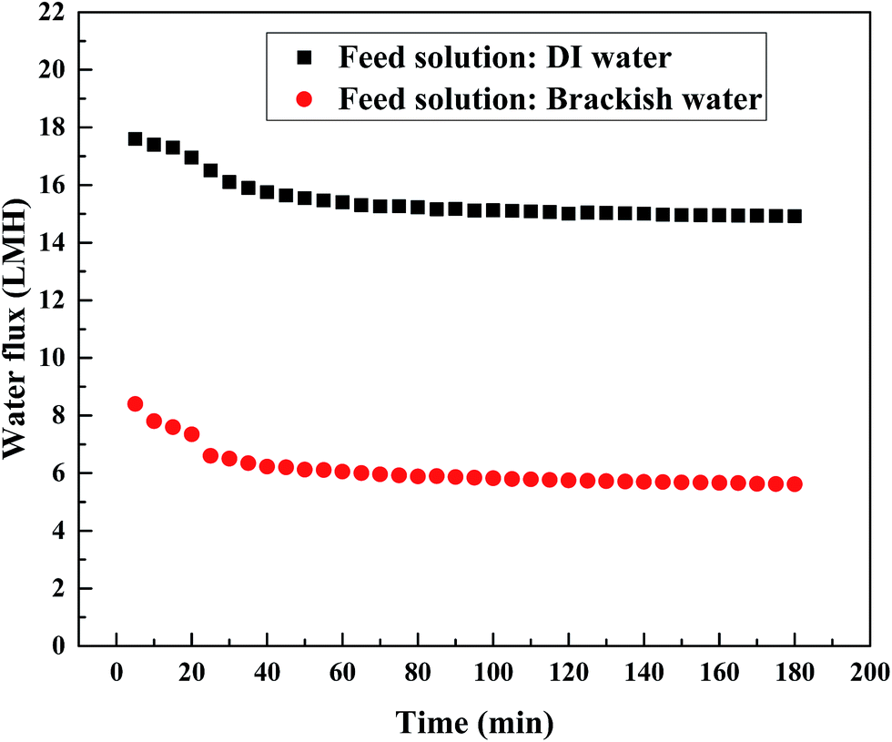
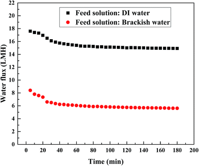
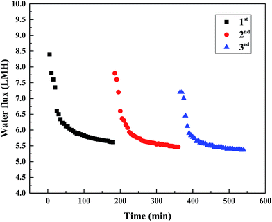
3.5.2 Brackish water desalination. For the brackish water desalination study, a PESA solution with the concentration of 0.2 g mL−1 as the DS and synthetic brackish water (0.3 M NaCl) as the feed solution were selected for use in the FO process at 25 °C. The variation in water flux in the entire 3 h is shown in Fig. 10, which compares the baseline when DI water was used as the feed solution under the same conditions (0.2 g mL−1 PESA and 25 °C). The desalination study was performed under the PRO mode. It can be seen that a considerable decline in water flux was observed when brackish water replaced DI water as the FS. A similar trend was observed by the previous studies using seawater as the feed solution.49 This may be due to the fact that brackish water generates a higher osmotic pressure than that of DI water, which reduces the osmotic pressure difference between the draw side and the feed side and leads to a drop in the water flux. In order to further investigate the feasibility of FO for brackish water desalination, the stability of the FO performance in terms of water flux was studied. Three FO tests were conducted under the same conditions (0.2 g mL−1 PESA, 25 °C and 17 cm s−1) using the same membrane and the fouled membrane was cleaned by physically flushing freshwater through the fouled polyamide surface for 1 h after each test. As shown in Fig. 11, a very stable and reproducible water flux was achieved. Compared to the first test, the average water flux of the second and third tests was restored to about 96.2% and 93.2%, respectively. This indicates that simple physical flushing can effectively rejuvenate the fouled membrane and the average water flux can be restored to about 93.2% even after 3 cycles. This again demonstrates the potential of using PESA as the draw solute for brackish water desalination.
 |
| | Fig. 10 Comparison of the PESA performance in terms of water flux with DI water and brackish water as feed solutions and 0.2 g mL−1 PESA as the draw solution in the PRO mode at the temperature of 25 °C and velocity of 17 cm s−1. | |
 |
| | Fig. 11 Reduction in water flux with time in the PRO mode using brackish water as the feed solution and 0.2 g mL−1 PESA as the draw solution. Membranes were cleaned by physical flushing for 1 h and then reused. | |
3.6 Recovery of PESA draw solution via NF
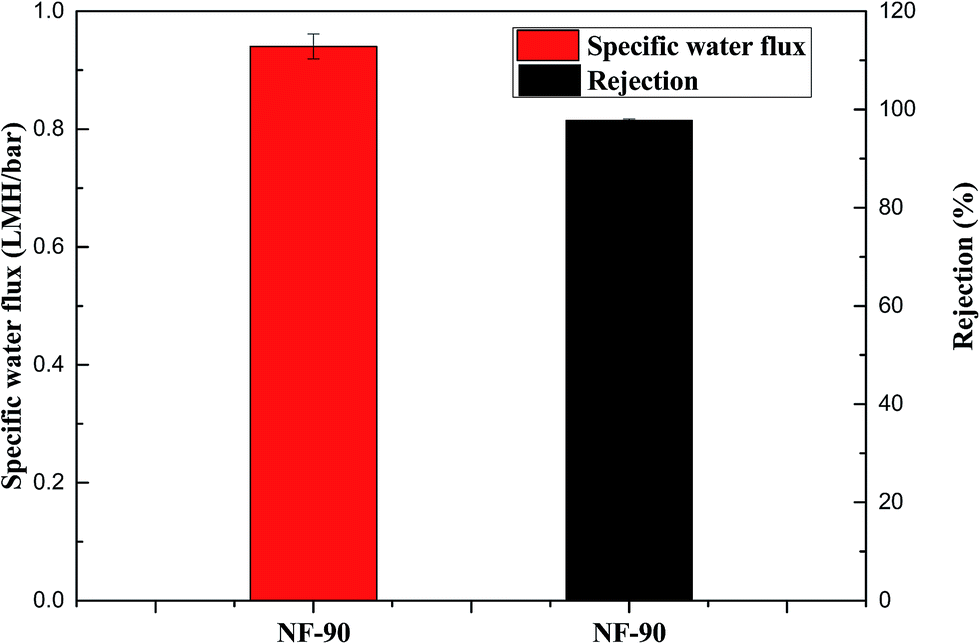
In order to investigate the feasibility of PESA recovery, a recovery study was conducted using a pressure-driven NF process. A dilute PESA solution with a concentration of 0.03 g mL−1 was used as the feed solution. The experiments were conducted at the operating pressure of 20 bar and temperature of 25 ± 1 °C. The specific water flux refers to the ratio of water flux to hydraulic pressure, which is used as an indicator of recovery efficiency. As shown in Fig. 12, the specific water flux and the PESA solute rejection rate were 0.94 LMH per bar and 97.8%, respectively. According to the procedure by Gwak et al.,31 0.03 g mL−1 PASP solution was used as the NF feed solution and its specific water flux and rejection rate were 0.4 LMH per bar and 98.9%, respectively. Compared to the PASP solution, the PESA solution had a better specific water flux performance and comparable rejection rate. To improve the rejection rate, other recovery methods such as membrane distillation should be further investigated.
 |
| | Fig. 12 Recovery of PESA solution using the NF-90 membrane (pressure: 20 bar; diluted PESA solution concentration: 0.03 g mL−1 and temperature: 25 ± 1 °C). | |
4. Conclusion
In this study, the polyelectrolyte PESA was applied as the draw solute in the FO process. Its characteristics of high solubility in water, expanded molecular structure, low viscosity, non-toxicity, and relatively high osmotic pressure could provide favorable FO performances and easy solute regeneration in post treatments. Furthermore, the diluted PESA solution could be used in many cooling water systems since PESA is a green scale inhibitor. The FO performances of PESA, PASP and NaCl were studied and compared. The influence of concentration, temperature, cross flow velocity and membrane orientation on FO performance using PESA as the draw solute was investigated. Besides, 0.2 g mL−1 PESA was chosen as a representative for dyeing wastewater treatment and brackish water desalination. The recovery experiments were conducted using the NF process with 0.03 g mL−1 PESA as the feed solution.
Compared to PASP and NaCl, the loss of PESA in recovering a liter of water from the feed side was low, which not only reduces contamination in the feed side but also saves the replenishment cost of the PESA draw solute. The effect of temperature on water flux was obvious, but the increase in water flux from 35 °C to 45 °C was much less than that from 25 °C to 35 °C in both the PRO and FO modes. Therefore, from the point of view of energy conservation it is preferable to conduct the FO process at a temperature below 35 °C. An increased cross flow velocity could promote water flux but its influence was minor in the FO mode. Compared to the FO mode, the water flux difference under three flow rates was more obvious in the PRO mode due to the reduction of CICP. Thus, a high flow rate in the PRO mode is preferable when using PESA as the draw solute. The use of PESA as the DS in the FO process to treat dyeing water shows the advantages of stable water flux, high dye rejection and reversible membrane fouling. Moreover, the NF process indicates the good performance of PESA recovery with a high specific water flux (0.94 LMH per bar) and rejection rate (97.8%). Thus, the overall performance of PESA demonstrates that it is a promising draw solute.
Acknowledgements
This work was supported by the Taishan Scholar Program (No. ts201511003).
References
- M. Elimelech and W. A. Phillipt, Science, 2011, 333, 712–717 CrossRef CAS PubMed.
- M. A. Montgomery and M. Elimelech, Environ. Sci. Technol., 2007, 41, 17–24 CrossRef PubMed.
- Q. Ge, J. Su, G. L. Amy and T. S. Chung, Water Res., 2012, 46, 1318–1326 CrossRef CAS PubMed.
- K. P. Lee, T. C. Arnot and D. Mattia, J. Membr. Sci., 2011, 370, 1–22 CrossRef CAS.
- L. F. Greenlee, D. F. Lawler, B. D. Freeman, B. Marrot and P. Moulin, Water Res., 2009, 43, 2317–2348 CrossRef CAS PubMed.
- D. L. Shaffer, J. R. Werber, H. Jaramillo, S. Lin and M. Elimelech, Desalination, 2015, 356, 271–284 CrossRef CAS.
- T.-S. Chung, S. Zhang, K. Y. Wang, J. Su and M. M. Ling, Desalination, 2012, 287, 78–81 CrossRef CAS.
- R. Valladares Linares, Z. Li, S. Sarp, S. S. Bucs, G. Amy and J. S. Vrouwenvelder, Water Res., 2014, 66, 122–139 CrossRef CAS PubMed.
- A. J. Ansari, F. I. Hai, W. Guo, H. H. Ngo, W. E. Price and L. D. Nghiem, Sci. Total Environ., 2016, 566–567, 559–566 CrossRef CAS PubMed.
- K. Lutchmiah, A. R. Verliefde, K. Roest, L. C. Rietveld and E. R. Cornelissen, Water Res., 2014, 58, 179–197 CrossRef CAS PubMed.
- Y. Cai, R. Wang, W. B. Krantz, A. G. Fane and X. M. Hu, RSC Adv., 2015, 5, 97143–97150 RSC.
- J. R. McCutcheon, R. L. McGinnis and M. Elimelech, J. Membr. Sci., 2006, 278, 114–123 CrossRef CAS.
- A. Sagiv, A. Zhu, P. D. Christofides, Y. Cohen and R. Semiat, J. Membr. Sci., 2014, 464, 161–172 CrossRef CAS.
- D. Zhao, S. Chen, P. Wang, Q. Zhao and X. Lu, Ind. Eng. Chem. Res., 2014, 53, 16170–16175 CrossRef CAS.
- N. T. Hau, S.-S. Chen, N. C. Nguyen, K. Z. Huang, H. H. Ngo and W. Guo, J. Membr. Sci., 2014, 455, 305–311 CrossRef.
- N. C. Nguyen, S. S. Chen, H. Y. Yang and N. T. Hau, Bioresour. Technol., 2013, 132, 224–229 CrossRef CAS PubMed.
- H. Zhu, L. Zhang, X. Wen and X. Huang, Bioresour. Technol., 2012, 113, 207–213 CrossRef CAS PubMed.
- M. M. Ling and T.-S. Chung, J. Membr. Sci., 2011, 372, 201–209 CrossRef CAS.
- Q. Ge, M. Ling and T.-S. Chung, J. Membr. Sci., 2013, 442, 225–237 CrossRef CAS.
- A. Zhou, H. Luo, Q. Wang, L. Chen, T. C. Zhang and T. Tao, RSC Adv., 2015, 5, 15359–15365 RSC.
- H. T. Nguyen, N. C. Nguyen, S. S. Chen, H. H. Ngo, W. Guo and C. W. Li, Sci. Total Environ., 2015, 538, 129–136 CrossRef CAS PubMed.
- M. Yasukawa, S. Mishima, Y. Tanaka, T. Takahashi and H. Matsuyama, Desalination, 2017, 402, 1–9 CrossRef CAS.
- T. P. N. Nguyen, B.-M. Jun and Y.-N. Kwon, J. Membr. Sci., 2017, 523, 111–121 CrossRef CAS.
- J. Ren and J. R. McCutcheon, Desalination, 2014, 343, 187–193 CrossRef CAS.
- A. Achilli, T. Y. Cath and A. E. Childress, J. Membr. Sci., 2010, 364, 233–241 CrossRef CAS.
- J. R. McCutcheon, R. L. McGinnis and M. Elimelech, Desalination, 2005, 174, 1–11 CrossRef CAS.
- D. Li, X. Zhang, G. P. Simon and H. Wang, Water Res., 2013, 47, 209–215 CrossRef CAS PubMed.
- S. Phuntsho, J. E. Kim, M. A. H. Johir, S. Hong, Z. Li, N. Ghaffour, T. Leiknes and H. K. Shon, J. Membr. Sci., 2016, 508, 22–31 CrossRef CAS.
- Y. Cui, Q. Ge, X.-Y. Liu and T.-S. Chung, J. Membr. Sci., 2014, 467, 188–194 CrossRef CAS.
- Q. Long, L. Shen, R. Chen, J. Huang, S. Xiong and Y. Wang, Environ. Sci. Technol., 2016, 50, 12022–12029 CrossRef CAS PubMed.
- G. Gwak, B. Jung, S. Han and S. Hong, Water Res., 2015, 80, 294–305 CrossRef CAS PubMed.
- Q. Long and Y. Wang, AIChE J., 2016, 62, 1226–1235 CrossRef CAS.
- P. Zhao, B. Gao, S. Xu, J. Kong, D. Ma, H. K. Shon, Q. Yue and P. Liu, Chem. Eng. J., 2015, 264, 32–38 CrossRef CAS.
- J. Duan, E. Litwiller, S.-H. Choi and I. Pinnau, J. Membr. Sci., 2014, 453, 463–470 CrossRef CAS.
- R. C. Ong, T.-S. Chung, J. S. de Wit and B. J. Helmer, J. Membr. Sci., 2015, 473, 63–71 CrossRef CAS.
- N. Widjojo, T.-S. Chung, M. Weber, C. Maletzko and V. Warzelhan, Chem. Eng. J., 2013, 220, 15–23 CrossRef CAS.
- P. Zhao, B. Gao, Q. Yue, S. Liu and H. K. Shon, Desalination, 2016, 378, 67–73 CrossRef CAS.
- Y. Zhao, Y. Ren, X. Wang, P. Xiao, E. Tian, X. Wang and J. Li, Desalination, 2016, 378, 28–36 CrossRef CAS.
- S. K. Yen, F. Mehnas Haja, N. M. Su, K. Y. Wang and T.-S. Chung, J. Membr. Sci., 2010, 364, 242–252 CrossRef CAS.
- D. Liu, W. Dong, F. Li and F. Hui, Desalination, 2012, 304, 1–10 CrossRef CAS.
- L. Dangni and T. Bing, Ind. Water Treat., 2012, 32 Search PubMed.
- W. Xiao, P. Ming, W. Shuhai and W. Yaquan, Spec. Petrochem., 2012, 29 Search PubMed.
- L. Xinhua, L. Wenzhi, K. Yichao and W. Qinghui, Surf. Technol., 2010, 39 Search PubMed.
- H. T. Nguyen, S.-S. Chen, N. C. Nguyen, H. H. Ngo, W. Guo and C.-W. Li, J. Membr. Sci., 2015, 489, 212–219 CrossRef CAS.
- S. Zürcher and T. Graule, J. Eur. Ceram. Soc., 2005, 25, 863–873 CrossRef.
- G. Gadelha, M. S. Nawaz, N. P. Hankins, S. J. Khan, R. Wang and C. Y. Tang, Desalination, 2014, 354, 97–106 CrossRef CAS.
- S. Phuntsho, S. Vigneswaran, J. Kandasamy, S. Hong, S. Lee and H. K. Shon, J. Membr. Sci., 2012, 415–416, 734–744 CrossRef CAS.
- J. R. McCutcheon and M. Elimelech, J. Membr. Sci., 2006, 284, 237–247 CrossRef CAS.
- R. Kumar, S. Al-Haddad, M. Al-Rughaib and M. Salman, Desalination, 2016, 394, 148–154 CrossRef CAS.
- A. H. Hawari, N. Kamal and A. Altaee, Desalination, 2016, 398, 98–105 CrossRef CAS.
- S. Phuntsho, S. Sahebi, T. Majeed, F. Lotfi, J. E. Kim and H. K. Shon, Chem. Eng. J., 2013, 231, 484–496 CrossRef CAS.
|
| This journal is © The Royal Society of Chemistry 2017 |
Click here to see how this site uses Cookies. View our privacy policy here. 
 Open Access Article
 This Open Access Article is licensed under a
  *a,
Pin Zhaoa,
Ruihua Lia,
Qinyan Yuea and
Ho Kyong Shonb
*a,
Pin Zhaoa,
Ruihua Lia,
Qinyan Yuea and
Ho Kyong Shonb