 Open Access Article
Creative Commons Attribution 3.0 Unported Licence
Dewetting of a pre-patterned thin polymer bilayer: influence of the instability mode
Lin Xua,
Zhengjian Chen *a and
Zhiming Zou
 *b
*b
aLaboratory of Surface Physics and Chemistry, Guizhou Education University, Guiyang 550018, P. R. China. E-mail: chzhengjian@163.com
bGuangxi Key Laboratory of Electrochemical and Magneto-Chemical Functional Materials, College of Chemistry and Bioengineering, Guilin University of Technology, Guilin, Guangxi 541004, P. R. China. E-mail: 2014005@glut.edu.cn
First published on 18th April 2017
Abstract
In this paper, the influence of film thickness on the layer instability mode of a thin polymer bilayer (poly(methylmethacrylate) (PMMA)/polystyrene (PS)/Si substrate) has been investigated. The experimental results show that kinetic forces can greatly influence the instability process of the thin polymer bilayer. In the case of PS-2.4K (Mw-PS = 2.4 kg mol−1), only the PS layer ruptures between the PMMA layer and the solid substrate and the dewetting is kinetically controlled. In the case of PS-31K (Mw-PS = 31 kg mol−1), the instability of the polymer bilayer changes from a kinetically controlled one to a thermodynamically controlled one with the increase of PS film thickness. In the case of PS-97K (Mw-PS = 97 kg mol−1), only the PMMA layer ruptures on the PS layer and the dewetting process is a thermodynamically controlled one. Besides, the influence of the instability mode on the template-assisted dewetting process of the thin polymer bilayer also was studied. After annealing the pre-patterned bilayer, in the case of the kinetically controlled dewetting, the PMMA film bends to conform to the buried PS–PMMA interface and concave half cylinder grooves form during the dewetting process; however, in the case of the thermodynamically controlled dewetting, PMMA chains move to the top of cylinder stripes and obvious trenches are found after PMMA chains are etched. This proposes a simple method to obtain different surface structures by changing the instability mode of the thin polymer bilayer.
Introduction
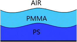
Polymer patterns are important not only in fundamental scientific research but also in various applications such as DNA array technology, biological optics, electronic devices, and microfluidic devices.1–5 The precise control of dewetting structures has been widely reported as a simple, effective and non-destructive method to fabricate ordered polymer patterning.6–9 One of the main approaches is to control the dewetting structures via the assistance of templates. Previous papers have reported template-directed and template-assisted dewetting in fabricating different micro- and nanoscale structures over large areas.10–14 Recently, many studies indicated that the dewetting of the bilayer has distinct advantages over the single layer in fabricating ordered micro/nano structures.15–30 The template-directed and template-assisted dewetting of the thin polymer bilayer have been investigated extensively due to their technological and scientific importance.31–35 Mukherjee et al.32,33 reported the dewetting process of a thin bilayer of polystyrene and poly(methylmethacrylate) on a topographically patterned nonwettable substrate, and using this method they fabricate many different structures. Ding et al.34,35 used the template-directed dewetting of the thin polymer bilayer to create many hierarchical structures by adjusting the geometry and properties of the individual layers. Compared to the single film scenario, the dewetting process of bilayer is more interesting because it grows via simultaneous instability of the coupled polymer/air, polymer/polymer, and polymer/solid substrate interfaces. More dewetting pathways of the thin polymer bilayer enrich the preparation of different structures. The instabilities of the thin polymer bilayers are generally governed by the thermodynamic forces. However, some recent studies36–44 have indicated that kinetic forces also greatly influence the instability of the thin polymer bilayer, as a result the instability could become a kinetically controlled one. Bandyopadhyay et al.36 have shown that a marked decrease in the viscosity of the upper layer increases the rate of deformation of the upper interface, causing the instability shifting back to the upper interface. Our previous paper43 has reported that the interfacial slip effect can greatly influence the instability mode of the thin polymer bilayer. Although the kinetically and thermodynamically controlled bilayer dewetting processes have been widely investigated, there are still many intriguing open questions. The important one is that the influence of kinetic forces on the instability modes of the bilayer is still unclear. Moreover, the interplay between these kinetic and thermodynamic forces in polymer bilayer system can bring richer dewetting pathways and more interesting surface and interfacial morphologies. Thus, this is especially attractive in fabricating and miniaturization of self-organized ordered micro/nano structures.Previous studies10–14,31–35 on the template-directed or template-assisted dewetting of the thin polymer films mainly focus on the influence of the geometry and size of the template pattern on the dewetting structures. In this paper, we concentrate on the influence of instability mode on the template-assisted dewetting process of the thin polymer bilayer. Firstly, we investigated the effect of the film thickness on the instability mode. The schematic diagram of the thin polymer bilayer system is shown in Fig. 1. In our experiments, the instability process of the thin polymer bilayer can shift from a thermodynamically controlled one to a kinetically controlled one via changing the thickness of polymer films. Then we studied the influence of instability mode on the template-assisted dewetting process of the thin polymer bilayer. It is interesting to find that different structures can be fabricated via adjusting the instability mode from a thermodynamically controlled one to a kinetically controlled one.
Experimental section
The experimental system under investigation was the bilayer system of poly(methylmethacrylate) (PMMA)/polystyrene (PS)/Si substrate, which was prepared in the following manner. PS films (Mw = 2.4 kg mol−1, 10 kg mol−1, 31 kg mol−1, 97 kg mol−1; Mw/Mn < 1.1, obtained from Aldrich) were spin coated from a toluene solution onto the Si wafer without the oxide layer. The Si wafers were cleaned in a bath of a 2/1 (v/v) solution of 98% H2SO4/30% H2O2 for 30 min, rinsed with deionized water, and then dried with nitrogen.The oxide layer on Si wafer was removed via hydrofluoric acid. PMMA films (Mw = 350 kg mol−1; Mw/Mn < 2, obtained from Aldrich) were spin coated from a chloroform solution onto mica and subsequently floated onto the surface of de-ionized water, and then deposited onto the PS films to form a bilayer. The residual solvent was removed by putting the films in a vacuum oven for 24 h at room temperature and the thicknesses of these films (hPS and hPMMA) were measured by ellipsometry (MM-16, HORIBA Jobin Yvon, France). After drying, these polymer films were annealed at 180 °C (well above the glass transition of both the polymers) under air. The surface and interfacial morphologies were observed by optical microscopy (OM, ZEISS Microsystems, Germany) in reflection mode with a CCD camera attachment and atomic force microscopy (AFM, Seiko Instruments Inc., Japan) operating in the tapping mode. The spring constant of the cantilever is 2 N m−1. The cantilever oscillated close to its resonance frequency between 65 and 75 kHz. The PMMA upper layers were removed by immersing the samples in its selective solvent (acetic acid) in order to characterize the PMMA–PS interfacial morphologies.45 After being dried, the remaining PS surface was imaged to obtain the morphology of the PS/PMMA interface. The selective solvent did not influence the morphologies of the remaining PS layer. Ordered PDMS template was obtained via copying the pattern of commercially available Compact Discs (CD). Contact angles of two different liquids (water and glycerin) on the Si substrate and polymer films were measured by drop shape analysis (KRUSS, Germany) at room temperature. We measured three points on every substrate to obtain the mean value. The error of the contact angles was less than 5%. The values of contact angles were utilized to calculate the surface energies of the Si substrate and polymer films via the method of harmonic mean.42,46
Results and discussion
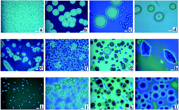
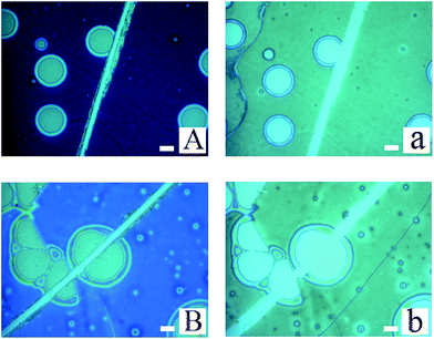
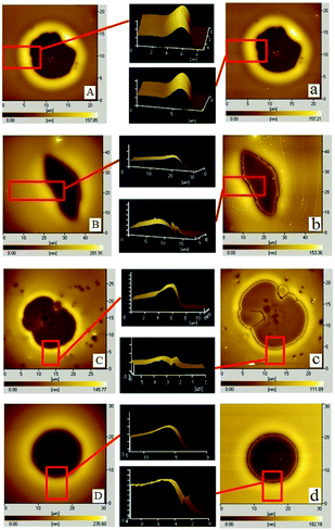
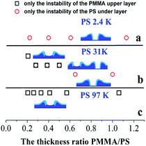
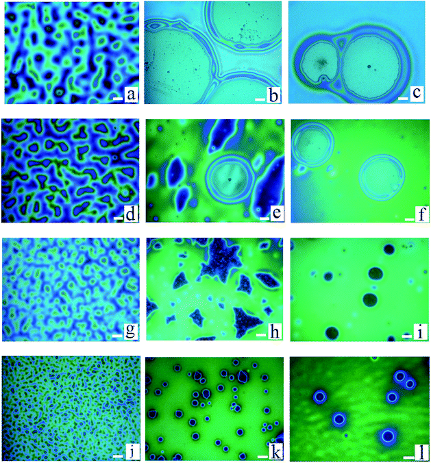
During the dewetting process of the thin polymer bilayer, the film thickness is an important parameter to influence its instability mode. The optical microscopy (OM) images listed in Fig. 2 present the influence of the thickness of the PS under layer on the instability process. In the case of PS-2.4K (Mw = 2.4 kg mol−1), the colors of the holes floors are almost the same (Fig. 2a–d). In the case of PS-31K (Mw = 31 kg mol−1), there are two obviously different colors of the holes floors in Fig. 2f and g. So there are probably two different instability modes. In the case of PS-97K (Mw = 97 kg mol−1), the colors of holes floors change from light gray to brown, last to blue. In order to disclose their instability modes, the dewetted structures were treated by acetic acid, which is a selective solvent for dissolution of PMMA but not for PS. In the case of PS-2.4K, the OM images in Fig. 3 are used to present the surface morphologies of the dewetting structures and the buried PMMA/PS interface, respectively, because of the relative large size of holes. A scratch is made on the position of the reference hole. Fig. 3 shows that a color difference between the holes floors and the naked Si substrate before etching PMMA layer (see Fig. 3A and B), and it disappears after the PMMA layer is etched (see Fig. 3a and b). This implies that the PMMA layer remains in the dewetted areas and the bilayer presents in other areas. Thus, only PS under layer ruptures between the PMMA layer and the solid substrate, while the PMMA films bend to conform to the buried PS–PMMA interface in the case of PS-2.4K.For the cases of PS-31K and PS-97K, we use the atomic force microscopy (AFM) images in order to obtain more detailed structures. The AFM images of the holes (before and after the film is treated with acetic acid) are shown in Fig. 4. Fig. 4A and a show that the shape of the rim does not have an obvious change and no trench is found in 3D AFM images of the rim. This implies that the instability of the bilayer is via the breakup of only PS layer. As shown in Fig. 4b–d, obvious trenches at the rims can be observed from 3D AFM images of the rim. This confirms that the dewetting is by the rupture of only PMMA layer on the PS layer. Fig. 5 lists the change of instability modes with the thickness ratio between the PMMA layer and the PS layer derived from Fig. 3 and 4. It is seen that for the bilayer systems with different Mw PS layer, the change of instability modes with thickness ratio is completely different.
From the thermodynamic aspect, the effective Hamaker constant of film is a main parameter to determine the stability of a thin film. Generally, a positive (negative) equilibrium effective Hamaker constant signifies instability (stability). In the system of thin polymer bilayer, the effective Hamaker constant can be expressed in terms of dispersion component of each surface tension:25
 | (1) |
 | (2) |
 | (3) |
The surface energy of polymer films slightly changes with the Mw of polymer (for PS: γd2 = 28.3 ± 0.5 mN m−1 and for PMMA: γd3 = 33.5 ± 0.5 mN m−1) from our experimental results. Applying the eqn (1)–(3) to the system of the thin bilayer film with a high Mw PMMA upper layer on the Si wafer without the oxide layer in air (γd1 = 35.6 mN m−1, γd2 = 28.3 ± 0.5 mN m−1, γd3 = 33.5 mN m−1, and γd4 = 0), we can get the effective Hamaker constant of the system, A123 = 5.7 × 10⁻¹⁹ mN m > 0, A234 = 5.095 × 10⁻¹⁸ mN m > 0, and A1234 = −7.049 × 10⁻¹⁸ mN m < 0. In the case of bilayer system, the Gibbs free energy for the upper layer and the under layer are given by:25,36
| ΔG(hupper)LW = −A234/12πhupper2 − A1234/12π(hupper + hunder)2 | (4) |
| ΔG(hunder)LW = −A123/12πhunder2 − A1234/12π(hunder + hupper)2 | (5) |
Without considering the kinetic forces, applying the eqn (4) and (5) to our bilayer systems, we found for all cases, ΔG(hPMMA)LW < 0 and ΔG(hPS)LW > 0. Thus, PMMA upper layer is unstable and PS under layer is stable in all our bilayer systems without considering kinetic forces. It is consistent with the experimental result for the case of PS-97K that PMMA upper layer ruptures on the PS layer (see Fig. 2i–l). The results are consistent with thermodynamic calculation results. For the case of PS-2.4K, it is found that the instability mode is different from thermodynamic calculation result and the PS under layer ruptures between the PMMA under layer and the solid substrate (see Fig. 2a–d and 3). Thus, the instability of the polymer bilayer is a kinetically controlled one. For the case of PS-31K, the instability process of thin polymer bilayer can shift from a thermodynamically controlled one to a kinetically controlled one. Our experimental results show that the kinetic forces play an important role in the instability pathway of the polymer bilayer. Previous papers42,43 have reported that the strength of the intermolecular interactions can be redistributed in the bilayer due to the kinetic forces, and the interfacial slip effect can greatly influence the instability mode of thin polymer bilayer. From our above experimental results, it is found that both kinetic and thermodynamic forces can influence the spatiotemporal evolution of the thin polymer bilayer.
Besides, the thicknesses of PMMA upper layer are also changed in our experiments. Fig. 6 shows the surface morphologies of PMMA films (Mw = 350 kg mol−1, different thicknesses)/PS films (four different molecular weights: Mw = 2.4 kg mol−1, 10 kg mol−1, 31 kg mol−1, and 97 kg mol−1; hPS = 157 ± 6 nm)/Si wafer annealed at 180 °C. We found that as the thickness of PMMA is 10 nm, the rupture of PMMA film is induced via spinodal dewetting in all cases basing on the colors of holes floors. For the case of PS-2.4K (Mw = 2.4 kg mol−1), PS layers rupture between the PMMA layer and the solid substrate with the increase of the thickness of PMMA films. In the case of PS-10K (Mw = 10 kg mol−1), as the increasing the thickness of PMMA upper layer, because there are two obvious different colors of holes floors (see Fig. 6e), indicating two instability modes occur during the dewetting process of the polymer bilayer. With further increasing the thickness of PMMA upper layer, we can only observe the breakup of only PS layer between the PMMA layer and the solid substrate. There is a switchover of the instability of polymer bilayer from PMMA layer to PS layer in the case of PS-10K. However, for the cases of PS-31K (Mw = 31 kg mol−1) and PS-97K (Mw = 97 kg mol−1), with the increase of the thickness of PMMA films, some irregular holes form in the dewetting process of the polymer bilayer. When the PMMA layer further becomes thick, all holes are circular and no irregular hole is found. The irregular holes are induced by the strong slippage effect of PMMA chains.40
In the following, we investigated the influence of the instability mode on the surface morphology during the template-assisted dewetting process of the thin polymer bilayer. We used ordered PDMS template to pre-pattern the thin polymer bilayers at 180 °C and then anneal them at 180 °C. Firstly, the two polymer bilayer systems with the same film thickness are chosen and they are bilayer I: PMMA (Mw = 350 kg mol−1, 40 ± 2 nm)/PS (Mw = 2.4 kg mol−1, 96 ± 3 nm)/Si substrate and bilayer II: PMMA (Mw = 350 kg mol−1, 40 ± 2 nm)/PS (Mw = 97 kg mol−1, 96 ± 3 nm)/Si substrate, respectively. The instability of bilayer I is controlled by kinetic forces; however, the dewetting of bilayer II is thermodynamically controlled.
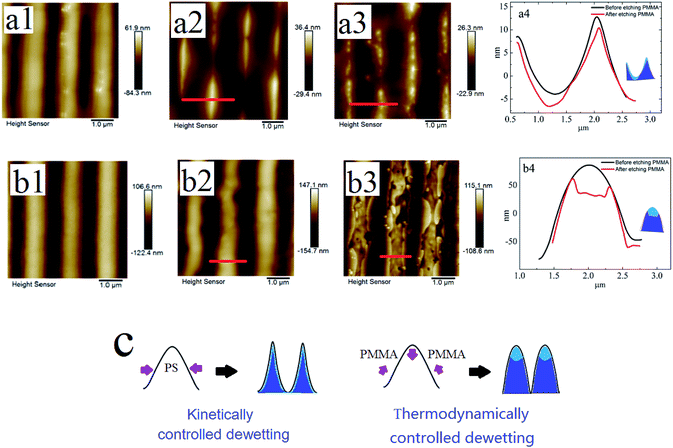
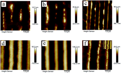
Fig. 7a1 and b1 show the surface morphologies of bilayer I and II pre-patterned at 180 °C for 1 min. Fig. 7a2 and b2 show the surface morphologies after annealing pre-patterned films at 180 °C for 2 min. As shown in Fig. 7a2 and b2, different surface structures are fabricated via the template-assisted dewetting of the two polymer bilayer systems. After the PMMA layer is removed, the morphologies of PS–PMMA interface are shown in Fig. 7a3 and b3. Fig. 7a4 and b4 show the AFM profile images of the surface morphologies at the position of red line. We can find that the PMMA film bends to conform to the buried PS–PMMA interface in the case of PS-2.4K. Mukherjee et al.33 have presented that the continuous PMMA bottom layer ruptures over the substrate stripes due to the geometry of substrate, while the top PS layer comes in direct contact with the substrate and subsequently rupture over the same locations, resulting in core shell threads localized over the substrate grooves. In our case, the high viscous of PMMA film is much more stable against local variations in its thickness because it requires less energy to make a simple bending. Finally, concave half cylinder grooves form during the instability process. However, in the case of PS-97K, PMMA is mainly collected on the top of cylinder stripes (see Fig. 7b3 and b4). During the thermodynamically controlled dewetting process, PMMA layer breaks up on the PS layer. With the increase of the thickness of the PS film, it offers a lower viscous resistance and larger deformation in the dewetting process. After pre-patterned bilayer II is annealed, PMMA chains move to the top of cylinder stripes because of the larger deformation of PS/PMMA interface on the position. Thus, obvious trenches can be observed on the top after PMMA chains are etched (see Fig. 7b3 and b4). Fig. 7c shows the schematic diagram of the formation of different surface morphologies. The influence of thickness of PS film is investigated in our experiments. Fig. 8 show the surface morphologies of different bilayer systems pre-patterned at 180 °C for 1 min and annealed pre-patterned films at 180 °C for 2 min. When the thicknesses of PS layer are smaller than 96 ± 3 nm, the formation processes of surface morphologies (Fig. 8a, b, d, and e) do not have obvious different with that of bilayer I and bilayer II (Fig. 7a2 and b2) in both cases of PS-2.4K and PS-97K. However, when the thickness of PS layer is 125 nm, every cylinder stripe divides into two undulating stripes in the case of PS-2.4K (see Fig. 8c), and PS and PMMA alternating stripes are observed in the case of PS-97K (see the inset of Fig. 8f). The viscous resistance decreases in the stripes with the increase of the thickness of PS layer. In the case of low viscous PS-2.4K, the Laplace and disjoining pressures in the stripes induce the fluctuation on the lateral direction of the stripes and the direction along the stripes. Thus, every cylinder stripe divides into two undulating stripes. During the thermodynamically controlled dewetting process, PMMA chains more easily move on the top of the stripes due to the lower viscous resistance and finally form PS and PMMA alternating stripes. Our experimental results indicate that different structures can be adjusted via changing the instability process from a thermodynamically controlled one to a kinetically controlled one. The dewetting of thin polymer bilayer can bring richer and more interesting surface and interfacial morphologies.
Conclusion
We have investigated the layer instability of thin polymer bilayer and the influence of instability mode on the template-assisted dewetting process of thin polymer bilayer. In the case of PS-97K, only PMMA layer ruptures on the PS under layer. The instability of the polymer bilayer is a thermodynamic controlled one, in consistent with thermodynamic calculation. In the case of PS-2.4K, only PS layer ruptures between the PMMA layer and the solid substrate, different from thermodynamic calculation. The instability of the polymer bilayer is a kinetically controlled one. In the case of PS-31K, the instability of the polymer bilayer shifts from the PS layer to the PMMA layer with the increase of PS film thickness. Thus, the instability processes shift from a kinetically controlled one to a thermodynamically controlled one. In a word, in addition to thermodynamics forces, the kinetic forces also become an important factor to influence the instability modes of the bilayer system. Besides, during the template-assisted dewetting process of thin polymer bilayer, different surface structures can be fabricated via adjusting the instability process from a thermodynamically controlled one to a kinetically controlled one.Acknowledgements
This work is supported by the National Natural Science Foundation of China (51503048 and 21504018) and the Construction Project of Key Laboratories from the Education Department of Guizhou Province (No. QJHKY[2015]329).References
- S. C. Thickett, C. Neto and A. T. Harris, Adv. Mater., 2011, 23, 3718–3722 CrossRef CAS PubMed.
- G. Stoychev, S. Zakharchenko, S. Turcaud, J. W. C. Dunlop and L. Ionov, ACS Nano, 2012, 6, 3925–3934 CrossRef CAS PubMed.
- C. Y. Li, M. Koslowski and A. Strachan, Nano Lett., 2014, 14, 7085–7089 CrossRef CAS PubMed.
- S. J. Yu, Y. Ni, L. H. He and Q. L. Ye, ACS Appl. Mater. Interfaces, 2015, 7, 5160–5167 CAS.
- N. L. Y. Wu, K. D. Harris and J. M. Buriak, ACS Nano, 2013, 7, 5595–5606 CrossRef CAS PubMed.
- A. M. Higgins and R. A. L. Jones, Nature, 2000, 404, 476–478 CrossRef CAS PubMed.
- R. Mukherjee, M. Gonuguntla and A. Sharma, J. Nanosci. Nanotechnol., 2007, 7, 2069–2075 CrossRef CAS PubMed.
- N. Bhandaru, A. Das, N. Salunke and R. Mukherjee, Nano Lett., 2014, 14, 7009–7016 CrossRef CAS PubMed.
- D. C. Hyun, M. Park, C. J. Park, B. Kim, Y. Xia, J. H. Hur, J. M. Kim, J. J. Park and U. Jeong, Adv. Mater., 2011, 23, 2946–2950 CrossRef CAS PubMed.
- K. Y. Suh, Y. S. Kim and H. H. Lee, Adv. Mater., 2001, 13, 1386–1389 CrossRef CAS.
- C. M. Bruinink, M. Peter, P. A. Maury, M. de Boer, L. Kuipers, J. Huskens and D. N. Reinhoudt, Adv. Funct. Mater., 2006, 16, 1555–1565 CrossRef CAS.
- K. Y. Suh, M. C. Park and P. Kim, Adv. Funct. Mater., 2009, 19, 2699–2712 CrossRef CAS.
- D. Ho, J. Zou, B. Zdyrko, K. S. Iyer, I. Luzinov and I. Luzinov, Nanoscale, 2015, 7, 401–414 RSC.
- D. C. Hyun, RSC Adv., 2015, 5, 76321–76329 RSC.
- M. Zawodzki, R. Resel, M. O. Kettner and B. Friedel, ACS Appl. Mater. Interfaces, 2015, 7, 16161–16168 CAS.
- S. C. Thickett, J. Moses, J. R. Gamble and C. Neto, Soft Matter, 2012, 8, 9996–10007 RSC.
- D. Bandyopadhyay, A. Sharma and C. Rastogi, Langmuir, 2008, 24, 14048–14058 CrossRef CAS PubMed.
- D. Bandyopadhyay and A. Sharma, J. Phys. Chem. C, 2010, 114, 2237–2247 CAS.
- L. Xu, D. Bandyopadhyay, T. F. Shi, L. J. An, A. Sharma and S. W. Joo, Polymer, 2011, 52, 4345–4354 CrossRef CAS.
- Y. P. Wang, P. Han, G. L. Wu, H. P. Xu, Z. Q. Wang and X. Zhang, Langmuir, 2010, 26, 9736–9741 CrossRef CAS PubMed.
- A. Sandstrom, P. Matyba, O. Inganas and L. Edman, J. Am. Chem. Soc., 2010, 132, 6646–6647 CrossRef PubMed.
- J. Gomez, F. Sagues and R. Reigada, J. Chem. Phys., 2010, 132, 135104 CrossRef PubMed.
- A. Pototsky, M. Bestehorn, D. Merkt and U. Thiele, Phys. Rev. E, 2004, 70, 025201 CrossRef PubMed.
- A. Pototsky, M. Bestehorn, D. Merkt and U. Thiele, J. Chem. Phys., 2005, 122, 224711 CrossRef PubMed.
- J. P. De Silva, M. Geoghegan, A. M. Higgins, G. Krausch, M.-O. David and G. Reiter, Phys. Rev. Lett., 2007, 98, 267802 CrossRef CAS PubMed.
- S. Merabia and J. B. Avalos, Phys. Rev. Lett., 2008, 101, 208304 CrossRef PubMed.
- H. Nazaripoor, C. R. Koch and S. Bhattacharjee, Langmuir, 2014, 30, 14734–14744 CrossRef CAS PubMed.
- A. Hens, K. Mondal and D. Bandyopadhyay, Phys. Rev. E, 2013, 87, 022405 CrossRef PubMed.
- A. Hens, K. Mondal, G. Biswas and D. Bandyopadhyay, J. Colloid Interface Sci., 2016, 465, 128–139 CrossRef CAS PubMed.
- D. C. Hyun, M. Park and U. Jeong, J. Mater. Chem. C, 2016, 4, 10411–10429 RSC.
- N. Bhandaru, A. Das, N. Salunke and R. Mukherjee, Nano Lett., 2014, 14, 7009–7016 CrossRef CAS PubMed.
- N. Bhandaru, A. Das and R. Mukherjee, Nanoscale, 2016, 8, 1073–1087 RSC.
- S. Roy, D. Biswas, N. Salunke, A. Das, P. Vutukuri, R. Singh and R. Mukherjee, Macromolecules, 2013, 46, 935–948 CrossRef CAS.
- Z. Zhang, D. U. Ahn and Y. Ding, Macromolecules, 2012, 45, 1972–1981 CrossRef CAS.
- D. U. Ahn and Y. Ding, Soft Matter, 2011, 7, 3794–3800 RSC.
- D. Bandyopadhyay and A. Sharma, J. Chem. Phys., 2006, 125, 054711 CrossRef PubMed.
- M. H. Ward, Phys. Fluids, 2011, 23, 062105 CrossRef.
- R. V. Craster and K. O. Matar, J. Fluid Mech., 2000, 425, 235–258 CrossRef.
- L. S. Fisher and A. A. Golovin, J. Colloid Interface Sci., 2005, 291, 515–528 CrossRef CAS PubMed.
- L. Xu, A. Sharma and S. W. Joo, Macromolecules, 2011, 44, 9335–9340 CrossRef CAS.
- L. Xu, A. Sharma and S. W. Joo, J. Phys. Chem. C, 2012, 116, 21615–21621 CAS.
- L. Xu, D. Bandyopadhyay, A. Sharma and S. W. Joo, Soft Matter, 2011, 7, 8056–8066 RSC.
- L. Xu, H. H. Zhang and T. F. Shi, Polymer, 2016, 99, 185–192 CrossRef CAS.
- S. Jachalski, D. Peschka, A. Münch and B. Wagner, J. Eng. Math., 2014, 86, 9–29 CrossRef CAS.
- T. Xu, J. T. Goldbach, M. J. Misner, S. Kim, A. Gibaud, O. Gang, B. Ocko, K. W. Guarini, C. T. Black, C. J. Hawker and T. P. Russell, Macromolecules, 2004, 37, 2972–2977 CrossRef CAS.
- S. J. Wu, J. Polym. Sci., Part C: Polym. Symp., 1971, 34, 19–30 CrossRef.
| This journal is © The Royal Society of Chemistry 2017 |

