
 Open Access Article
 This Open Access Article is licensed under a
 Creative Commons Attribution 3.0 Unported Licence
Carbon fibers/ZnO nanowires hybrid nanogenerator based on an insulating interface barrier†
Yunzhe Du,
Chuankai Fu,
Yunzhi Gao,
Li Liu *,
Yawei Liu,
Lixin Xing and
Feng Zhao
*,
Yawei Liu,
Lixin Xing and
Feng Zhao
School of Chemistry and Chemical Engineering, Harbin Institute of Technology, Harbin, Heilongjiang 150001, China. E-mail: liuli@hit.edu.cn
First published on 18th April 2017
Abstract
Nanogenerators (NGs) based on the piezoelectric property of ZnO nanowires (NWs) have become an important component to harvest mechanical energy from the environment. In one category of ZnO NGs, the high-work function noble metal electrode is applied to deflect ZnO NWs, and electricity is generated due to the Schottky barrier formed between ZnO NWs and the noble metal. Herein, an insulating layer was used to replace the expensive noble metal to accumulate net charge, and a novel NG was composed by carbon fibers (CFs) and ZnO NWs. Because of a relative slip among CFs, ZnO NWs would generate inner potential by bending each other. Due to the combination of an enormous number of ZnO NWs, an electric output of 2 mV and 0.2 nA was generated. Current–voltage curves indicated the entire ohmic contact of the designed NG, while electrochemical impedance spectroscopy demonstrated the existence of an interface barrier. Since a noble metal electrode was avoided in the ZnO NG, the manufacturing cost was reduced and the fabrication process was simplified. This study proposes a novel strategy for designing feasible ZnO NG in extensive applications.
Introduction
There are various forms of energies existing in the ambient environment such as solar, thermal and mechanical energies. With the rapid development of wearable electric devices,1–3 harvesting environmental energies to power these devices has attracted a lot of research attention.4–6 After the vital discovery of ZnO nanowires (NWs) in converting mechanical energy into electricity,7 a large number of studies have been involved in this field.8–10 At present electric signals of direct-current (DC)11 and alternating-current (AC)12 have been successfully generated, and the shapes of ZnO nanogenerators (NGs) could be various modes such as fiber,13 member14 and textile.15 In addition, ZnO could also be assembled with other functional materials16 to harvest different energy forms17 due to its outstanding performances in different fields. This impressive progress strongly extended the application scope of ZnO NGs.In recent years, microfiber-ZnO NWs hybrid NG has played an important role for harvesting biomechanical energy from humans.13,15,18 This type of NG could be woven into any shape to adapt to different environments, and operate at the low motion frequency of the human body. In general, the weavable NG are composed of two types of fibers, where one of the fibers is covered with metal (Au or Pd) coated ZnO NWs to bend the ZnO NWs on the other fiber. Electricity is generated from the Schottky barrier formed between ZnO NWs and the high work-function noble metal. However, the requirement of expensive noble metal strongly increases manufacturing cost and processes of these types of ZnO NGs. In previous studies, the Schottky barrier has been successfully replaced by an insulating interface;19–21 however, the strategy has not been applied in microfiber-ZnO NW hybrid NGs. Once an insulating layer is introduced into the interface between ZnO NWs and the metal electrode, the inner resistance of the ZnO NG system greatly increases, which blocks the electricity output. Thus, how to replace the expensive high work-function noble metal with an insulating layer has been a significant challenge of the microfiber-ZnO NWs hybrid NG.
In addition, organic fibers are used to fabricate microfiber-nanowire hybrid NGs.13,15,18 However, organic fibers are electroinsulating and they always need a layer of metal film to conduct electricity. Thus, the use of flexible, designable and conductive materials to replace insulating organic fibers will be a benefit for this design. Carbon fiber (CF) with a good intrinsic conductivity and small diameter of about several micrometers is a good choice for fabricating flexible ZnO NGs. In this study, CFs were applied as the substrate for growing ZnO NWs, and simultaneously an insulating layer between CF and ZnO NWs was used to establish an interface barrier. During a relative slip among CFs, the ZnO NWs generated inner electric potential due to their piezoelectric property by bending each other. Eventually, an electrical output of 2 mV and 0.2 nA was generated. Because high work-function noble metal was not used in the NG, the junctions between ZnO NWs and electrodes were ohm contacts according to the I–V characteristics. Moreover, electrochemical impedance spectroscopy (EIS) indicated the existence of an interface barrier, which was an essential factor for the ZnO NG. In the design, an interface barrier was established between the ZnO fixed end and the CFs electrode, and thus the use of an insulating layer between the electrode and the free end of the ZnO NWs was avoided. Simultaneously, because of the same electrical attributes of the stretched sides of two ZnO NWs, no current leaked through the contact point. Due to these artful designs, electricity was successfully outputted.
Results and discussion
CF (T800HB-12000) was selected as the substrate material and possessed high strength and modulus and excellent electrical conductivity. Thus CF not only acted as a woven material but also as a conductive electrode. Fig. 1 shows typical scanning electron microscope (SEM) images of CF after each modification step. A homogeneous ZnO film (Fig. 1a) was coated on the CF surface acting as the crystal seed for subsequent growth of the ZnO NWs. Remarkably, the ZnO seeds formed a continuous film rather than separate quantum dots, thus the ZnO film could be the common electrode for collection of electric charge. Then, ZnO NWs were prepared using a hydrothermal method, and they presented a hexagonal prism monocrystal structure. In addition, there was enough space for ZnO NWs to embed in, and the ZnO NWs could be bent by each other (Fig. 1b). X-ray diffraction (XRD) measurements were applied to demonstrate the crystalline structure of ZnO NWs. The results indicated that the ZnO NWs presented a hexagonal wurtzite structure, and no impurity was generated in their production (Fig. S2 in the ESI†).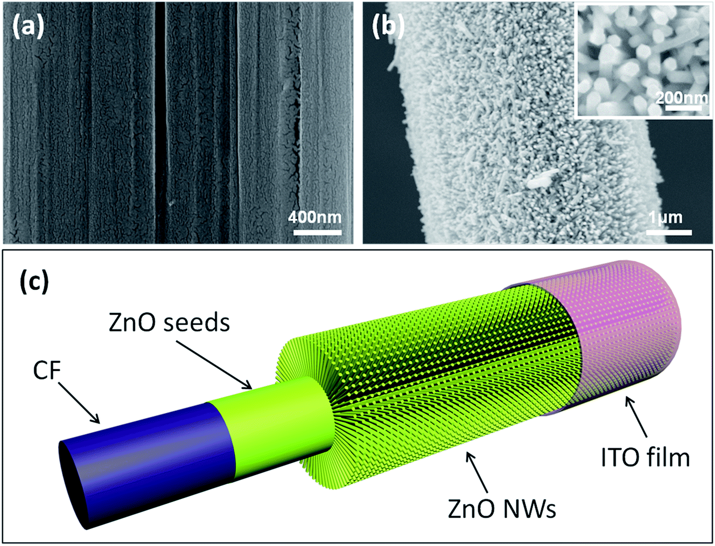 | ||
| Fig. 1 (a) Carbon Fiber (CF) covered with a layer of ZnO seeds. (b) Radial ZnO nanowires (NWs) grown on the CF, and high magnification SEM image of ZnO NWs (inset). (c) Diagram of the basic nanogenerator (NG) unit consisting of CF, ZnO seeds, ZnO NWs and indium tin oxide (ITO) film. | ||
At one end of the CFs, the as-growth ZnO NWs were etched by acid to expose the bare CFs as one electrode; at the other end, ZnO NWs were covered with indium tin oxide (ITO) film, which acted as another electrode. In this research, ITO film was loaded onto a soft polyethylene terephthalate (PET) substrate. In order to achieve effective electrical contact, 5 MPa pressure was put on the contact area between the ITO film and the ZnO NWs. With this pressure, ZnO NWs were embedded into the PET and contacted tightly with the ITO conductive film. This was a crucial process for electrical output. Previous research indicated that inner resistance would strongly block the piezoelectric current.13 When the ITO film was thinly coated on the ZnO NWs surface, no electric signal was detected because of the large interface resistance. Fig. 1c presents a complete structure of the as designed NG, which consists of the CFs electrode, ZnO seeds, ZnO NWs and ITO electrode. The detailed fabrication processes are presented in the Experimental section and ESI.†
A bunch of commercial CFs (T800HB-12000) was composed with 12![[thin space (1/6-em)]](https://www.rsc.org/images/entities/char_2009.gif) 000 single CFs with diameters around 5 μm. Each CF was covered with dense, uniform and radial ZnO NWs (Fig. S3†). A periodic contraction and extension deformation was applied on CFs twice a second in this experiment, which is similar to the human walk frequency (Fig. 2b). During the deformation, ZnO NWs would move with the CFs, and the interpenetrated ZnO NWs would bend each other (Fig. 2c). Due to the piezoelectric property of every single ZnO NW, electrical potential was generated between its two ends. An electrochemical workstation was used to detect the open-circuit voltage. At first, bare CFs were connected with the working electrode, the ITO films were connected with the counter electrode, and positive potential was detected around 2 mV (Fig. 2e). Subsequently, the two electrodes of the electrochemical workstation were reversely connected with NG, and the output potential was reversed simultaneously (Fig. 2f). Thus, possible artefacts were ruled out that might have been caused by the detection system.
000 single CFs with diameters around 5 μm. Each CF was covered with dense, uniform and radial ZnO NWs (Fig. S3†). A periodic contraction and extension deformation was applied on CFs twice a second in this experiment, which is similar to the human walk frequency (Fig. 2b). During the deformation, ZnO NWs would move with the CFs, and the interpenetrated ZnO NWs would bend each other (Fig. 2c). Due to the piezoelectric property of every single ZnO NW, electrical potential was generated between its two ends. An electrochemical workstation was used to detect the open-circuit voltage. At first, bare CFs were connected with the working electrode, the ITO films were connected with the counter electrode, and positive potential was detected around 2 mV (Fig. 2e). Subsequently, the two electrodes of the electrochemical workstation were reversely connected with NG, and the output potential was reversed simultaneously (Fig. 2f). Thus, possible artefacts were ruled out that might have been caused by the detection system.
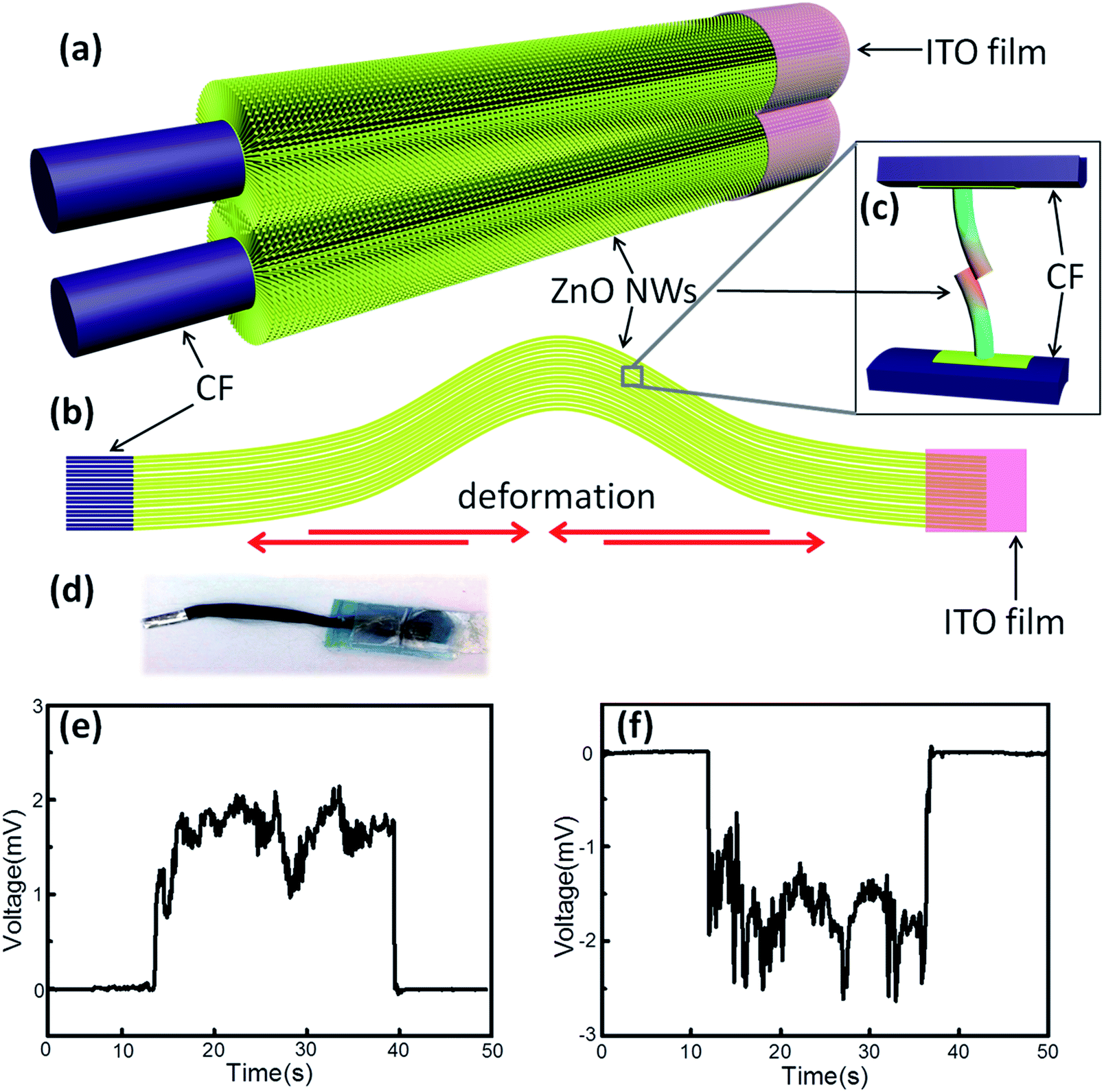 | ||
| Fig. 2 Processes of electricity generation. (a) Two adjacent CFs with ZnO NWs interpenetrating. (b) The deformed NG when it suffers from mechanical force. (c) Two bet ZnO NWs by each other because of the relative slip among the CFs; pink sides means the positive potential and blue bottoms means negative potential. (d) An optical graph of NG. (e) The output voltage when the CFs was connected with the working electrode and ITO films was connected with the counter electrode, respectively. (f) The output voltage after reversing the two electrodes connected to NG. | ||
In the present study, DC output was successfully generated by the designed NGs. In previous studies, most ZnO NGs were found to generate an AC-type output,12,22,23 which needed to be converted to DC by an extra rectification circuit. On the contrary, all of the microfiber-ZnO NWs hybrid NGs generated DC-type output.7 It is important to note that despite this, the NG generated DC output in this research, but the principles of these were significantly different. The latter DC output was caused by a Schottky barrier. Electric current was blocked when the metal tips came in contact with the stretching side of ZnO NWs. Once the metal tips touched the compressing side of the ZnO NWs, a sudden electrical output was be generated. In the present NG, no Schottky barrier existed. The electric output was attributed to the interface barrier between ZnO NWs and CFs. When CFs suffered from periodic movement, there was a slight relative slip among the CFs. Thus, ZnO NWs rarely had a chance to attach to their compressing sides. In other words, it is an expected situation that ZnO NWs kept in touch with their stretching sides and generated DC output.
When ZnO NWs were deflected, the stretching sides presented a positive potential. In this design, ZnO NWs were bent by each other through the movement of CFs, and the positive sides of the ZnO NWs kept in contact. Despite the barrier not existing between ZnO NWs, no current flowed through the contact point due to the same electrical attributes. At the other ends, ZnO NWs were fixed onto continuous ZnO films, which were linked with the ITO film. The conductive and flexible CFs was the other electrode to collect charge carriers. Fig. 3a shows the structure of the NG, which was a multilevel system. At the nanoscale, every couple of ZnO NWs could be regarded as a tiny generator. Along a single CF, an enormous number of ZnO generators were parallel together and electric current was gathered in the CF. Extending the scope to microscale, every single CF was as an enlarged generator and 12000 CFs were parallel as well. Finally, the electric current was gathered in one metal electrode. An equivalent circuit diagram is presented in Fig. 3b. An amperometric technique from the electrochemical workstation was applied to test the NG output current, and the external voltage was set to 0 V to rule out the interference caused by the detection system. Current signal around 0.2 nA was generated by the NG. When NG was reversely connected to the test electrodes, the current signal was reversed as well (Fig. 3c and d). This magnitude of electric output was comparable with the values in previous research studies,13,15,18 which could be attributed to the multilevel structure, even though highly conductive noble metal was not used. During the electricity generation process, the noise level of the voltage output was larger than the current. Constituent parts (ZnO NWs and CFs) of NG were parallelly connected, and thus the voltage was influenced by every ZnO NW generator.9 However, current output was the collection of all the tiny currents from the ZnO NWs, and thus was more stable than voltage output. In addition, the electrical output was continuous rather than intermittent like most fiber-NW hybrid NGs.13,15,18 Thus the NG could be used to power wearable electronics by harvesting biomechanical energy from humans. In order to evaluate the durability of the CFs/ZnO NWs NG, ZnO NWs morphologies were observed before and after electrochemical tests of 20 min (Fig. S4†). Compared with the original CFs/ZnO NWs system (Fig. S4a†), parts of the ZnO NWs were deformed and disordered after the electrochemical tests, which are shown in the red boxes of Fig. S4b.† Although the shapes changed for the ZnO NWs, the entire structure of the CFs/ZnO NWs system was stable, and thus the CFs/ZnO NWs NG would be durable for long time use.
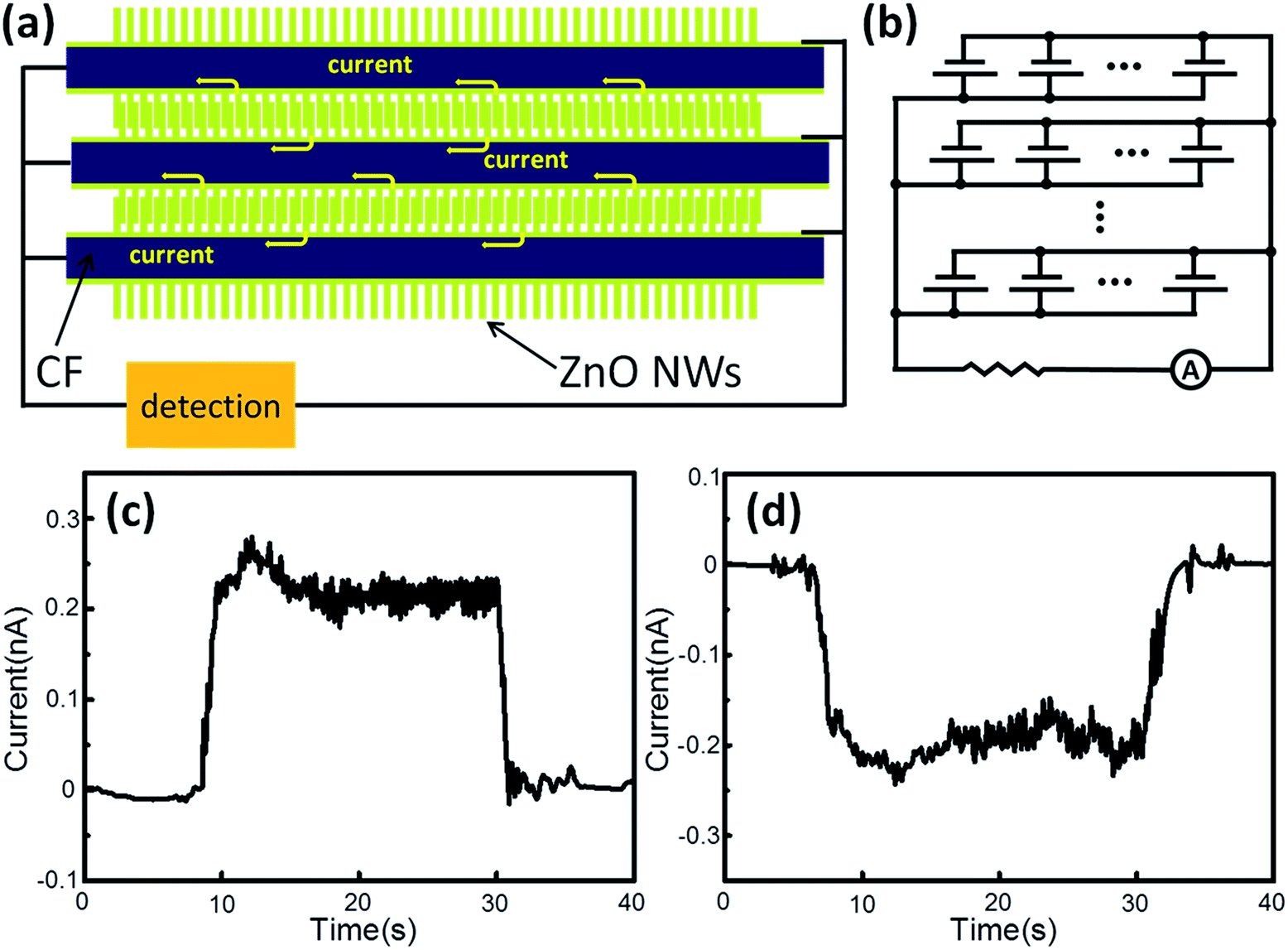 | ||
| Fig. 3 (a) Diagram of the inner ZnO NG structure. The yellow arrows represent enormous weak currents generated by ZnO NWs. (b) The equivalent circuit diagram corresponding to the generator system. (c) The output current when the CFs were connected with the working electrode, and the ITO films were connected with the counter electrode, respectively. (d) The output current after reversing the two electrodes connected to NG. | ||
In the ZnO NG system, the interface barrier was an essential constituent, which was always provided by a Schottky barrier between ZnO and the noble metal. However in the present NG, a Schottky barrier did not exist according to the I–V curve (Fig. 4a). In order to prove the interface barrier in another form, we tested the impedance character of the NG. EIS clearly indicated the existence of interface capacitance (Fig. 4b), which played an important role to accumulate net charge and generate electrical output. In fact, CFs would accept the oxidation pretreatment and be covered with a polymer layer to protect them from surface damage before the CFs left the factory.24 Energy dispersive X-ray spectrometry (EDS) results indicated the existence of the insulating layer and ZnO films on CFs (Fig. 4d and e). Thus, the insulating layer between ZnO film and CF could act as an interface barrier to prevent electric leakage. The insulating layer came from the sizing of CFs, and the sizing agent was a mixture of different compositions in which epoxy resin was the main component to protect the CF surface from damage.25,26 X-ray photoelectron spectroscopy (XPS) was applied to further indicate the composition of the insulating layer on the CF surface (Fig. S5†). The content of functional group C–O was 28.09%, which indicated the existence of an epoxy resin insulating layer on the CF surface (Table S1†).
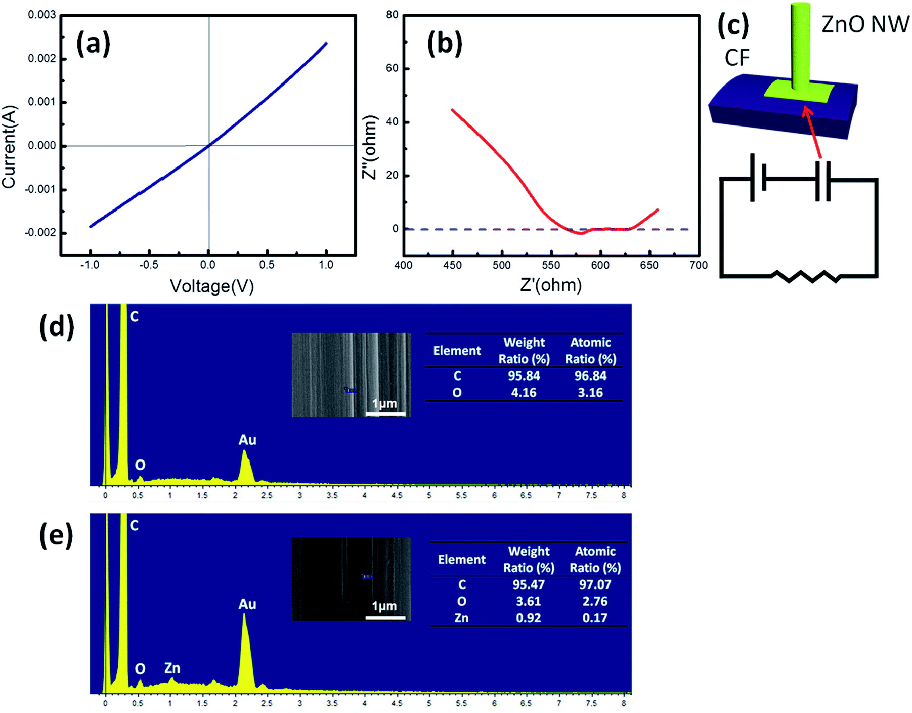 | ||
| Fig. 4 (a) The I–V characteristics of NG in the −1 to 1 V voltage range. (b) Electrochemical impedance spectroscopy (EIS) measured in the 0.1 Hz to 1 MHz frequency range. (c) Diagram of ZnO NW and CF, and the equivalent circuit containing the interface capacitance. (d) and (e) The energy dispersive X-ray spectrometer (EDS) results for the CF surface before and after covering with ZnO seeds, respectively, and the corresponding elementary composition. | ||
Unlike former designs, in which the external electrodes would come in contact with two ends of the ZnO NWs, in this NG, CFs and ITO film were not directly linked with the two ends of ZnO NWs. In the present design, CFs, ZnO films, the bottom ends of ZnO NWs, the stretching sides of ZnO NWs, and ITO film composed a continuous system. In this system, piezoelectric potential, which was generated by deflected ZnO NWs, would force the directional migration of charge carriers. Due to the obstructing action of the insulating layer, electric output was towards the external environment. This process is determined by the second law of thermodynamics, namely the principle of entropy increment.
Conclusions
In summary, the electrical output was successfully generated by the CF/ZnO NWs hybrid NG when the junctions between ZnO NWs and electrodes were ohm contacts. EIS testing indicated that the insulating layer between CFs and ZnO NWs could act as the interface barrier to accumulate net charge. Our study determined that the mechanism of the ZnO NGs:interface barrier was a crucial factor for the electrical output, which could be a Schottky barrier or insulating barrier. In the NG, a high work-function noble metal was avoided by use of the insulating layer, which strongly reduced the manufacturing cost of the ZnO NG. The application of flexible and conductive CFs as an electrode further simplified the fabrication process. This study proposes a novel design of ZnO NG and provides a way to convert biomechanical energy of humans into electric energy.Experimental
Materials
Carbon fibers (CFs) (T800HB-12000) were purchased from Toray Industries, Inc. Before use, contaminants of the CFs were removed by Soxhlet extraction with acetone for 48 h. Sodium hydroxide (NaOH), sulfuric acid (H2SO4), zinc acetate dehydrate [Zn(CH3COO)2·2H2O], zinc nitrate hexahydrate [Zn(NO)3·6H2O] and hexamethylenetetramine (HMTA) were purchased from Sinopharm Chemical Reagent Co., Ltd., China and used as received. PET–ITO [polyethylene terephthalate (PET) coated with indium tin oxide (ITO)] film with a sheet resistance of 5 ohm sq−1 was purchased from Zhuhai Kaivo Optoelectronic Technology Co., Ltd., China and used as received.Synthesis of ZnO nanowires (NWs) on CFs
ZnO NWs were synthesized following a two-step method. First, a layer of ZnO seeds was coated on CFs. Furthermore, 1 mmol of Zn(CH3COO)2·2H2O was added into 80 mL of ethanol at 50 °C and vigorously stirred until it dissolved. Then, 2 mmol of NaOH was dissolved into 100 mL of ethanol at 50 °C under vigorously stirring. Both solutions were cooled to room temperature. 40 mL of Zn(CH3COO)2 ethanol solution and 40 mL of NaOH ethanol solution were dispensed and added to 320 mL and 100 mL of ethanol, respectively. Both solutions were heated to 65 °C and mixed in one beaker. The mixture was vigorously stirred at 65 °C. After 30 min, the beaker was put into ice water until the mixture was cooled to room temperature. Then, a stable colloidal suspension of ZnO seeds was obtained. CFs were dipped into the ZnO seeds solution for 15 min under vigorous stirring. The CFs were annealed at 150 °C for 10 min to enhance the bonding strength of the ZnO seeds on CFs. After three coating and annealing cycles, there was a layer of ZnO film on the CFs. The coated CFs were dipped into an aqueous solution of Zn(NO)3 (0.025 mol L−1) and HMTA (0.025 mol L−1), followed by heating at 90 °C. After 90 min ZnO NWs were synthesized on the CFs surface. The coated CFs were washed three times with deionized water, and then dried at 100 °C in atmosphere.Fabrication of ZnO nanogenerator (NG)
10 cm cut sections of CFs were covered with ZnO NWs. One end of the CFs was cleaned with H2SO4 (0.1 mol L−1) to remove ZnO and expose the bare CFs. The other end of the CFs was fixed on a PET film and covered with the ITO film; the ITO film should be stuck out about 1 cm to be an electrode. Then, the sandwich structure was under 5 Mpa pressure to combine them into a whole. Eventually the ZnO NG was completed, the bare CFs and ITO film were two electrodes connected to an external electric circuit.Performance characterization
The electrical performance was measured by an electrochemical workstation (CHI604D, Shanghai Chenhua Instruments Co., Ltd.). The open circuit potential–time technique was used to measure the NG electrical potential. The electric current was measured using an amperometric i–t technique, and the external voltage was set to 0 V to rule out the effect of the equipment. The I–V characteristics were obtained using cyclic voltammetry, by setting the low voltage and high voltage to be −1 and 1 V, respectively. The electrochemical impedance spectroscopy was measured in the 0.1 Hz to 1 MHz frequency range. A scanning electron microscope (Zeiss Sapphire Supra 55, Germany) was used to observe the CFs surface, and the morphologies of the ZnO seeds and ZnO NWs. The crystal structures of CFs and ZnO NWs were tested by an X-ray diffractometer (XRD, RIGAKU D/MAX-rβ, Japan) with Cu Kα radiation (λ = 1.5406 nm) generated at 40 kV and 100 mA. The X-ray photoelectron spectroscopy (XPS, ESCALAB 220i-XL, VG, UK) was applied to analyze the chemical structures of CFs surfaces with a monochromatic Al Kα source (1486.6 eV) at a base pressure of 2 × 10⁻⁹ mbar.Acknowledgements
The authors acknowledge the financial support from the National Natural Science Foundation of China (No. 51303040), the China Postdoctoral Science Foundation (No. 2013M541373, No. 2014T70329). The authors acknowledge the support of MIIT Key Laboratory of the Critical Materials Technology for New Energy Conversion and Storage, School of Chemistry and Chemical Engineering, Harbin Institute of Technology.Notes and references
- D. Son, J. Lee, S. Qiao, R. Ghaffari, J. Kim, J. E. Lee, C. Song, S. J. Kim, D. J. Lee, S. W. Jun, S. Yang, M. Park, J. Shin, K. Do, M. Lee, K. Kang, C. S. Hwang, N. Lu, T. Hyeon and D. Kim, Nat. Nanotechnol., 2014, 9, 397–404 CrossRef CAS PubMed.
- M. J. Cima, Nat. Biotechnol., 2014, 32, 642–643 CrossRef CAS PubMed.
- M. K. Choi, J. Yang, K. Kang, D. C. Kim, C. Choi, C. Park, S. J. Kim, S. I. Chae, T. Kim, J. H. Kim, T. Hyeon and D. Kim, Nat. Commun., 2015, 6, 7149 CrossRef CAS PubMed.
- P. D. Mitcheson, E. M. Yeatman, G. K. Rao, A. S. Holmes and T. C. Green, Proc. IEEE, 2008, 96, 1457–1486 CrossRef.
- N. S. Lewis, Science, 2007, 315, 798–801 CrossRef CAS PubMed.
- Y. Yang, W. Guo, K. C. Pradel, G. Zhu, Y. Zhou, Y. Zhang, Y. Hu, L. Lin and Z. L. Wang, Nano Lett., 2012, 12, 2833–2838 CrossRef CAS PubMed.
- Z. L. Wang and J. H. Song, Science, 2006, 312, 242–246 CrossRef CAS PubMed.
- Y. Qin, X. Wang and Z. L. Wang, Nature, 2008, 451, 809–813 CrossRef CAS PubMed.
- X. Wang, J. Song, J. Liu and Z. L. Wang, Science, 2007, 316, 102–105 CrossRef CAS PubMed.
- D. Shin, E. L. Tsege, S. H. Kang, W. Seung, S. Kim, H. K. Kim, S. W. Hong and Y. Hwang, Nano Energy, 2015, 12, 268–277 CrossRef CAS.
- M. K. Gupta, J. Lee, K. Y. Lee and S. Kim, ACS Nano, 2013, 7, 8932–8939 CrossRef CAS PubMed.
- R. Yang, Y. Qin, L. Dai and Z. L. Wang, Nat. Nanotechnol., 2008, 4, 34–39 CrossRef PubMed.
- Y. Qin, X. Wang and Z. L. Wang, Nature, 2008, 451, 809–813 CrossRef CAS PubMed.
- M. Y. Choi, D. Choi, M. J. Jin, I. Kim, S. H. Kim, J. Y. Choi, S. Y. Lee, J. M. Kim and S. W. Kim, Adv. Mater., 2009, 21, 2185–2189 CrossRef CAS.
- S. Bai, L. Zhang, Q. Xu, Y. Zheng, Y. Qin and Z. L. Wang, Nano Energy, 2013, 2, 749–753 CrossRef CAS.
- A. Ramadoss, B. Saravanakumar, S. W. Lee, Y. Kim, S. J. Kim and Z. L. Wang, ACS Nano, 2015, 9, 4337–4345 CrossRef CAS PubMed.
- Y. Yang, H. Zhang, G. Zhu, S. Lee, Z. Lin and Z. L. Wang, ACS Nano, 2013, 7, 785–790 CrossRef CAS PubMed.
- L. Zhang, S. Bai, C. Su, Y. Zheng, Y. Qin, C. Xu and Z. L. Wang, Adv. Funct. Mater., 2015, 25, 5794–5798 CrossRef CAS.
- R. Hinchet, S. Lee, G. Ardila, L. Montès, M. Mouis and Z. L. Wang, Adv. Funct. Mater., 2014, 24, 971–977 CrossRef CAS.
- S. Lee, S. Bae, L. Lin, Y. Yang, C. Park, S. Kim, S. N. Cha, H. Kim, Y. J. Park and Z. L. Wang, Adv. Funct. Mater., 2013, 23, 2445–2449 CrossRef CAS.
- S. Lee, R. Hinchet, Y. Lee, Y. Yang, Z. Lin, G. Ardila, L. Montès, M. Mouis and Z. L. Wang, Adv. Funct. Mater., 2014, 24, 1163–1168 CrossRef CAS.
- B. Saravanakumar, K. Thiyagarajan, N. R. Alluri, S. SoYoon, K. Taehyun, Z. Lin and S. Kim, Carbon, 2015, 84, 56–65 CrossRef CAS.
- S. Shin, Y. Kim, M. H. Lee, J. Jung, J. H. Seol and J. Nah, ACS Nano, 2014, 8, 10844–10850 CrossRef CAS PubMed.
- A. D. Jannakoudakis, P. D. Jannakoudakis, E. Theodoridou and J. O. Besenhard, J. Appl. Electrochem., 1990, 20, 619–624 CrossRef CAS.
- L. T. Drzal, M. J. Rich, M. F. Koenig and P. F. Lloyd, J. Adhes., 1983, 16, 133–152 CrossRef CAS.
- N. S. Broyles, R. Chan, R. M. Davis, J. J. Lesko and J. S. Riffle, Polymer, 1998, 39, 2607–2613 CrossRef CAS.
Footnote |
| † Electronic supplementary information (ESI) available: Schematic showing fabrication steps and X-ray diffraction (XRD) patterns of CFs and CFs covered with ZnO NWs. See DOI: 10.1039/c7ra02491f |
| This journal is © The Royal Society of Chemistry 2017 |