 Open Access Article
High-performance graphene-based flexible heater for wearable applications
Shu-Yu Lin†
 ac,
Tian-Yu Zhang†ab,
Qi Luab,
Dan-Yang Wangab,
Yi Yangab,
Xiao-Ming Wuab and
Tian-Ling Ren*ab
aInstitute of Microelectronics, Tsinghua University, Beijing 100084, China. E-mail: RenTL@tsinghua.edu.cn
bTsinghua National Laboratory for Information Science and Technology (TNList), Tsinghua University, Beijing 100084, China
cSchool of Materials Science and Engineering, Tsinghua University, 100084, China
First published on 22nd May 2017
Abstract
In this paper, a high-performance large-scale flexible heater based on graphene and silver particles is described. The graphene-based heater can be integrated into various systems without having to be too selective about the substrate used. When silver particles are mixed with graphene, the sheet resistance is greatly reduced to 158.7 Ω sq−1. A time-dependent temperature profile under an applied voltage of 18 V exhibits a steady-state temperature of up to 220 °C within 5 s. The high steady-state temperature and ultrafast response time are superior to those of most of the existing heaters. The infrared pictures show a uniform temperature distribution whether the graphene-based heater is flat or curved. Therefore, with the advantages of a low driving voltage, high steady-state temperature, ultrafast response and excellent flexibility, the graphene-based heater is expected to be a promising potential candidate for various wearable heating applications.
Introduction
Flexible electrothermal heaters have attracted a growing interest because of their broad applications in wearable electronics, including warming garments, and as flexural warmers for medical devices and vehicles.1 Traditional electrothermal materials such as ferro chromium (FeCr)-based alloys have disadvantages such as heavy weight, rigidity and low heating efficiency.2 Indium tin oxide (ITO) is widely used in commercial products because of its high transparency and high electrical conductivity. However, the finite reserve of indium has resulted in an increasing price of production, which is a drawback to its extensive use.3 Also, ITO has a slow thermal response, and worst of all, it is not suitable for flexible applications because of its fragility.4,5 For these reasons, a variety of materials have been studied as potential replacements for ITO.6 Among them, a metal nanostructure is one of the prospective candidates.7 With a low sheet resistance, heaters based on a metal nanostructure can be operated under low driving voltage. However, for the metal nanowire based heater, the junctions of the nanowires are prone to oxidation and failure at high temperatures.8 Whereas the fabrication of the metal nanomesh based film relies on crack templates, which are quite complicated.9 Furthermore, metal nanostructure film not only exhibits poor adhesion to plastic substrates,10 but also requires high-cost noble metal as raw material, such as gold (Au) and silver (Ag). All these weaknesses limit its application. Graphene is a two-dimensional (2D) nanomaterial which is widely used in sensors11 and transparent conductive film.12 Because of its low cost and light weight, graphene is deemed as another promising material for flexible electrothermal heaters. The atomic scale, hexagonal lattice endows graphene with an extraordinarily high thermal conductivity of 5300 W mK−1 (ref. 13) and outstanding mechanical performance.14 Furthermore, it is reported that the efficiency of the electrothermal heater is mainly determined by the convective heat loss. Compared to its counterparts, a graphene-based system bears a low convective heat transfer coefficient,15 which gives it its outstanding electrothermal performance. The previously mentioned advantages make graphene a promising alternative for next generation flexible heaters. However, most of the graphene-based heaters suffer from large sheet resistance2,16 and require a high input voltage when a high temperature is needed. For wearable devices, such a high voltage poses a potential danger to the human body. Thus, a low resistance heater is required to minimize the danger.Recently, for the sake of mutual compensation, strategies have been put forward to combine the two types of material previously described. Kang et al. fabricated a flexible heater based on a gold(III) chloride-doped graphene. Because of a 70% decline in resistance after doping, a remarkable electrothermal performance was achieved.17 Lee et al. demonstrated an Ag nanowire-graphene hybrid electrode and the low resistance electrode was successfully integrated into wearable soft contact lenses.10 Kim et al. utilized a wet coating process to fabricate a carbon nanotube (CNT)–Ag nanowire hybrid heater, which was applied for reducing haze. The device showed an increase in flexibility and electrical performance.18 However, although high performance was obtained, the fabrication of these hybrid structures is relatively complex.
In this paper, a high performance Ag particle/laser-reduced graphene oxide (LRGO) flexible heater is described, which combines the strength of both materials and can be easily fabricated on different substrates. Here, scanning electron microscopy (SEM), Raman spectra and X-ray photoelectron spectroscopy (XPS) were utilized to identify the quality of the hybrid film. A series of experiments was carried out to measure its electrothermal performance and flexibility. When a low driving voltage of 18 V was applied, the flexible heater reached a saturated temperature of 220 °C within only 5 s. Such an ultrafast response speed is hardly ever achieved in flexible heaters. The heater was also combined with traditional Chinese medicine to treat arthritis, which demonstrated an unexpected application of the flexible heater. Because of the previously mentioned advantages and the results of this study, this method was shown to have good potential for future wearable heating systems.
Materials and methods
Fabrication of GO/Ag particle film
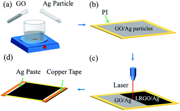
Compared to other electrothermal devices, the LRGO/Ag particle heater has a simple fabrication process, which does not rely on any expensive equipment or a special environment. The graphene oxide (GO) was purchased from Nanjing XFNANO Materials Tech Co., Ltd. The average diameter of the dispersed GO sheet is larger than 500 nm and the concentration is 2 mg mL−1. Ag particles with an average diameter of 0.8 μm were purchased from Changsha Weixi New Materials Technology Co., Ltd. First the Ag particles were dispersed in deionized water with a concentration of 10 mg mL−1. Then, the Ag particles and the GO suspension were mixed and the mixture was stirred continually for 2 h to produce the homogeneous suspension (Fig. 1a). The polyimide (PI) film with a thickness of 25 μm was chosen as the substrate for its outstanding thermal resistance. The film was rinsed with ethyl alcohol and then dried at room temperature. Then the mixed suspension was spread on the substrate by drop casting at a fixed level of 0.2 mL cm−2, which further determines the thickness of the thin film heater. The film is then volatilized naturally at room temperature for 24 h (Fig. 1b).Laser reduction
With laser processing, the GO is reduced. As is shown in Fig. 1c, the reduced area is a rectangle of 2 × 2.5 cm in size. The laser source has a wavelength of 650 nm with power of 143 μW and a scanning speed of 8.49 mm s−1. According to previous work, reducing the GO twice can greatly improve the electrothermal performance of the LRGO.19 Thus, the GO/Ag particle film was reduced twice. Then, the copper tape was pasted at the edge of the heater as the electrode and Ag paste was coated on the junction area to provide a stable electrical connection (Fig. 1d).Results and discussion
Fabrication on various substrates
For different applications, the electrothermal heater should be produced on different materials. Thus, the fabrication technique should not rely on the property of the substrate. As described previously, drop casting and laser reduction are two major steps in the fabrication of the LRGO/Ag particle heater, and either of these procedures have selectivity on the substrate. In this research, a uniform GO film was formed on various substrates, including a silicon wafer (Fig. 2a), a plastic dish (Fig. 2b) and curved bases, such as a glass lens (Fig. 2c). These examples illustrate the possibility of combining heater fabrication with a standard micro-electro-mechanical systems (MEMS) technique and realizing a common thermal related system, such as a thermos bottle and anti-freezing equipment. Also, GO manifests good adhesion on flexible substrates such as PI and poly(ethylene terephthalate) (PET) (Fig. 2d). As shown later, the LRGO/Ag particle film has excellent flexibility and shows an even temperature distribution under mechanical bending. These advantages prove the feasibility of achieving a high performance flexible heater. GO casting can even be done on fabrics (Fig. 2e) and natural materials (Fig. 2f), which indicates the underlying application in warming garments. All the above examples demonstrate the potential of building heating systems in various situations by the method proposed here.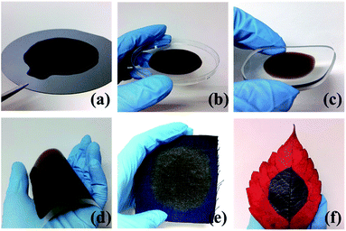 | ||
| Fig. 2 Fabrication of a uniform GO film on various substrates. GO solution coated on substrate of (a) silicon wafer, (b) plastic dish, (c) glass lens, (d) PET, (e) cloth, (f) leaf. | ||
Sample characterization
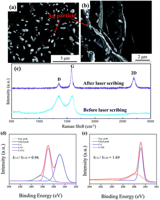
The microscopic characteristics of the LRGO/Ag particle thin film heater are shown in the SEM and Raman spectra. Fig. 3a shows the morphology of the volatilized GO/Ag particle film. It can be seen that the distribution of the Ag particles on the flat GO surface is random, which demonstrates the uniformity of the film before laser treatment. In the Raman spectra of the GO/Ag particle film, a highly broadened D band at around 1345 cm−1 and a G band at around 1590 cm−1 are observed, as shown in Fig. 3c, which are typical GO characteristics.20A further lasering process leads to the reduction of GO. In the Raman spectra, it is observed that the D and G peaks become sharper and separated, whereas the 2D peak appears at around 2700 cm−1. Also, the value of the intensity band ratio ID/IG for the D and G peaks decreases from 0.94 to 0.70, which indicates the decrease of defects in the sample.21 It is also observed that the G peak shifts to lower frequencies, from 1590 cm−1 to 1579 cm−1. Such a red shift is the typical feature of graphene crystallization.22 In the C 1s spectra of Ag–GO film (Fig. 3d), the experimental peaks can be fitted to 284.9 eV, 287.0 eV and 288.2 eV, which are assigned to the carbon–carbon single bond, the epoxide group (C–O–C), and the carbonyl group (C![[double bond, length as m-dash]](https://www.rsc.org/images/entities/char_e001.gif) O), respectively.23 After laser treatment, the epoxide group and carbonyl group are hard to detect in the spectra, while a distinct peak is shown at around 285.6 eV, which should be assigned to the hydroxyl/phenolic group (C–OH) (Fig. 3e). The result is similar to that obtained for thermally reduced GO.24 All the fitted peaks can be divided into two categories, C–C bonds and C–O bonds. After laser reduction, the intensity ratio of C–C bonds to C–O bonds increases from 0.96 to 1.69, which indicates the decrease of oxygen content. Furthermore, from the whole spectra, the atomic ratio of carbon to oxygen, which is calculated by dividing the area under the C 1s peak with that of the O 1s peak and multiplying it by the ratio of the photoionization cross section, increases from 1.91 to 7.26. The previous results show that GO is reduced sufficiently by laser processing twice.
O), respectively.23 After laser treatment, the epoxide group and carbonyl group are hard to detect in the spectra, while a distinct peak is shown at around 285.6 eV, which should be assigned to the hydroxyl/phenolic group (C–OH) (Fig. 3e). The result is similar to that obtained for thermally reduced GO.24 All the fitted peaks can be divided into two categories, C–C bonds and C–O bonds. After laser reduction, the intensity ratio of C–C bonds to C–O bonds increases from 0.96 to 1.69, which indicates the decrease of oxygen content. Furthermore, from the whole spectra, the atomic ratio of carbon to oxygen, which is calculated by dividing the area under the C 1s peak with that of the O 1s peak and multiplying it by the ratio of the photoionization cross section, increases from 1.91 to 7.26. The previous results show that GO is reduced sufficiently by laser processing twice.
In the SEM images shown in Fig. 3a and b, Ag particles are shown distributed among the graphene flakes. From this observation, it can be concluded that in the planar direction, Ag particles are uniformly distributed without obvious agglomeration and in the vertical direction, the particles exist between the layers, which guarantees an even distribution of temperature in the electrothermal measurement.
Electrothermal test
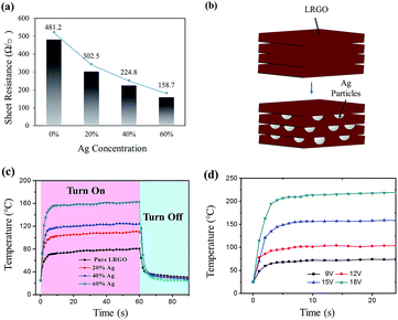
In the electrothermal test, GOs with 20%, 40% or 60% (wt%) of Ag particles were prepared. The samples are described as LRGO-20% Ag, LRGO-40% Ag and LRGO-60% Ag, respectively. The sheet resistance of the heaters with different concentrations of Ag particles are shown in Fig. 4a. In LRGO-60% Ag, the sheet resistance was 158.7 Ω sq−1. Compared to the 481.2 Ω sq−1 of pure LRGO, there is a more than 60% reduction, which proves that the Ag particles effectively increase the conductivity of the film. It is well known that graphite has a much smaller c-axis conductivity (σc) compared to its in-plane conductivity (σa). σa is proved to be about two orders of magnitude larger than σc,25 which is also similar for LRGO. As shown in Fig. 4b, when Ag particles are added into GO film, it will distribute evenly between the graphene layers, creating highly conductive paths in the c-axis. As both the c-axis and in-plane conductivity contribute to the overall conductivity, the reduction in sheet resistance can be easily explained by this.In Joule heating, electrical power is defined as P = U2/R. For the same power input, the decline of resistance will result in the reduction of driving voltage, which is consistent with the electrothermal measurement. Here, a direct current power is applied to the devices and their response was recorded by an infrared camera. When a driving voltage of 15 V was applied, the temperature of the heater increased rapidly over time until a steady-state temperature was reached. When the power was cut off, the temperature drops back to room temperature again at an equally high speed. The time dependence temperature profiles show that the saturated temperature increases monotonically with the augmentation of the Ag particle content in the film (Fig. 4c). In the sample of LRGO-60% Ag, the steady-state temperature reaches over 160 °C which is a 100% augmentation compared to the pure LRGO heater. From another perspective, to achieve the same temperature, there is a more than 30% reduction in the driving voltage for LRGO-60% Ag, according to the electrical power formula. In a wearable heating system, high driving voltage has a potential threat for the human body and sets a high requirement for the electric source. Thus, the high driving voltage, especially those above the secure voltage for the human body, which is 36 V, should be avoided. Also, as reported by Sui et al., a lower sheet resistance will result in a higher transduction efficiency of the electric energy to the Joule heat.14 The previous analysis suggests that Ag particles effectively increase the electrothermal performance of the film heater. Fig. 4d shows the electrothermal response of LRGO/60% Ag under voltages of 9 V, 12 V, 15 V and 18 V. The heater shows a steady-state temperature of 229 °C with a maximum heating rate of 89.6 °C s−1, when a voltage of 18 V is applied. With the restriction of low resistivity, a carbon material based flexible heater can hardly reach 200 °C under a driving voltage of less than 30 V.2,14,26 The response time, which is defined as the time it takes for the heater to reach the steady-state temperature from room temperature, is another crucial parameter in determining the dynamic performance of the flexible heater. In all measurements, an ultrashort response time of 5 s is recorded. Such a fast response rate overmatches most of the existing heaters.
In Table 1, the key parameters of several previous flexible heaters are listed. In this work, the heater has a lower sheet resistance than other carbon materials, such as CNTs and graphene prepared by other methods.27–32 The device also has a faster electrothermal response than all the other heaters, which should be credited to the high thermal conductivity and electrothermal transduction efficiency of the LRGO.
| Material | Sheet resistance (Ω □−1) | Driving voltage (V) | Response time (s) | Steady-state temperature (°C) | Ref. |
|---|---|---|---|---|---|
| Ag-doped LRGO | 158.7 | 18 | 5 | 229 | This work |
| TRGO | 641 | 60 | 10 | 206 | 14 |
| Doped graphene | 43 | 12 | 80 | 97 | 17 |
| Electrochemically exfoliated graphite | 159 | 30 | 20 | 139 | 2 |
| Ag nanowires | 33 | 7 | 200 | 53 | 7 |
| Ag mesh | 32.5 | 6 | 150 | 85 | 27 |
| Multi-walled CNTs | 349 | 12 | 50 | 65 | 28 |
| Single-walled CNTs | 580 | 12 | 60 | 95 | 26 |
| CNTs and Ag nanowires | 50 | 15 | 30 | 110 | 18 |
| Ag mesh and ITO | 300 | 12 | 43 | 10 | 29 |
| Ga doped ZnO | 10.7 | 12 | 48 | 88 | 30 |
| ITO nanoparticles | 633 | 20 | 110 | 163 | 31 |
| Fluorine-doped tin oxide | 253 | 12 | 700 | 39 | 32 |
Mechanical properties
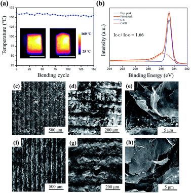
The inset of Fig. 5a shows the outstanding mechanical performance of the LRGO/Ag particle heater. In the test, the device was fixed in two conditions, flat and convex bending. Then the same power input of 1.9 W was applied and the temperature distribution was recorded using the infrared camera. The thermal images showed an even distribution in both situations, which are attributed to the high flexibility of the graphene film and the uniform distribution of Ag particles in the film.Then the LRGO-60% Ag heater was bent 150 times with a relative high bending frequency of 2 Hz (two cycles per second). Fig. 5a shows the average temperature of the heater during the durability test. From the profile, it can be seen that only a small temperature deviation of 8 °C was recorded, which is merely 5% of the average temperature. The excellent mechanical performance shown here suggests that the heater was suitable for use in flexible heating. To further explore the long-term performance of the heater, the LRGO-60% Ag heater was operated at 150 °C for 30 min. The change of content and surface morphology was recorded. The C 1s XPS spectrum of the film after heating is presented in Fig. 5b. The peak position and relative intensity basically remain unchanged when compared to the peaks in Fig. 3e. Only a small difference could be detected when the data were analysed in detail. The calculated atomic ratio of carbon to oxygen showed a small increase from 7.26 to 7.40, whereas the intensity ratio of the C–C bond to the C–O bond decreased from 1.69 to 1.66. The SEM images in Fig. 5c–e are the morphology of the heater before heating. After heating, there is no marked change in the morphology, which is shown in Fig. 5f–h. From the previous results, it was concluded that the LRGO/Ag heater was suitable for long-term operation.
Given such exceptional flexibility and stability under long-term operation, the LRGO/Ag particle heater can be easily integrated into wearable electronics. In this research, the heater was combined with traditional Chinese medicine and presents a novel application of a flexible heater. Here the heater is utilized to conduct a hot compress in treating arthritis. Arthritis is a crippling disease which affects a great number of people in China and using a hot compress is an effective Chinese medicine therapy. In the treatment, heating the joint to over 50 °C is known to be effective in promoting local blood circulation and relieving suffering. In Fig. 6, a LRGO/Ag particle heater on a PI substrate is affixed to the human elbow. When a direct current voltage of 15 V is applied, heat dissipated from the heater is transferred directly to the elbow because of the flexibility of the device. From the thermal image, the temperature of the elbow reaches around 70 °C and maintains an even distribution. Integrated into wearable devices, the heater can be used to treat arthritis effectively.
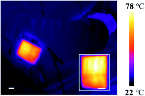 | ||
| Fig. 6 Prospective application of the heater. Utilizing the LRGO/Ag particle heater to treat arthritis of the elbow (scale of the ball is 2 cm). | ||
Conclusions
In conclusion, a graphene-based heater with outstanding electrothermal performance and high flexibility was fabricated using drop casting and laser reduction. This method has great potential for its industrialization because it requires little selectivity of substrate and it has universal applicability. Ag particles were utilized to effectively reduce the sheet resistance, which further led to the reduction of the driving voltage. It was shown that the LRGO/Ag particle heater can realize ultrafast high temperature heating within the safe level of voltage for the human body. Together with a high flexibility, the film heater can be integrated into various wearable applications, including a hot compress for treating arthritis. The result of this work is a great improvement of the LRGO heater, suggesting that there is a bright future for utilizing the graphene-based heater in future advanced wearable heating systems.Acknowledgements
This work was supported by the National Natural Science Foundation (61377106, 61574083, 61434001), the National Basic Research Program (2013CBA01604, 2015CB352100), the National Key Project of Science and Technology (2011ZX02403-002), and the Special Fund for Agroscientific Research in the Public Interest (201303107) of China. The Authors are thankful for the support of the Independent Research Program of Tsinghua University (2014Z01006), and the Advanced Sensor and Integrated System Lab of Tsinghua University Graduate School at Shenzhen under project ZDSYS20140509172959969.References
- S. Hong, H. Lee, J. Lee, J. Kwon, S. Han, Y. D. Suh, H. Cho, J. Shin, J. Yeo and S. H. Ko, Adv. Mater., 2015, 27, 4744–4751 CrossRef CAS PubMed.
- C. Li, Y.-T. Xu, B. Zhao, L. Jiang, S.-G. Chen, J.-B. Xu, X.-Z. Fu, R. Sun and C.-P. Wong, J. Mater. Sci., 2015, 51, 1043–1051 CrossRef.
- K. D. Rao and G. U. Kulkarni, Nanoscale, 2014, 6, 5645–5651 RSC.
- P. Li, J. G. Ma, H. Y. Xu, D. Lin, X. D. Xue, X. Z. Yan, P. Xia and Y. C. Liu, J. Alloys Compd., 2016, 664, 764–769 CrossRef CAS.
- R. E. Triambulo, H.-G. Cheong, G.-H. Lee, I.-S. Yi and J.-W. Park, J. Alloys Compd., 2015, 620, 340–349 CrossRef CAS.
- C. Z. Akshay Kumar, ACS Nano, 2010, 4, 11–14 CrossRef PubMed.
- C. Celle, C. Mayousse, E. Moreau, H. Basti, A. Carella and J.-P. Simonato, Nano Res., 2012, 5, 427–433 CrossRef CAS.
- H. Guo, N. Lin, Y. Chen, Z. Wang, Q. Xie, T. Zheng, N. Gao, S. Li, J. Kang, D. Cai and D. L. Peng, Sci. Rep., 2013, 3, 2323 CrossRef PubMed.
- S. Kiruthika, R. Gupta and G. U. Kulkarni, RSC Adv., 2014, 4, 49745–49751 RSC.
- M. S. Lee, K. Lee, S. Y. Kim, H. Lee, J. Park, K. H. Choi, H. K. Kim, D. G. Kim, D. Y. Lee, S. Nam and J. U. Park, Nano Lett., 2013, 13, 2814–2821 CrossRef CAS PubMed.
- Y. Zhu, Y. Hao, E. A. Adogla, J. Yan, D. Li, K. Xu, Q. Wang, J. Hone and Q. Lin, Nanoscale, 2016, 8, 5815–5819 RSC.
- X. Li, Y. Zhu, W. Cai, M. Borysiak, B. Han, D. Chen, R. D. Piner, L. Colombo and R. S. Ruoff, Nano Lett., 2009, 9, 4359–4363 CrossRef CAS PubMed.
- A. A. Balandin, S. Ghosh, W. Bao, I. Calizo, D. Teweldebrhan, F. Miao and C. N. Lau, Nano Lett., 2008, 8, 902–907 CrossRef CAS PubMed.
- D. Sui, Y. Huang, L. Huang, J. Liang, Y. Ma and Y. Chen, Small, 2011, 7, 3186–3192 CrossRef CAS PubMed.
- J. J. Bae, S. C. Lim, G. H. Han, Y. W. Jo, D. L. Doung, E. S. Kim, S. J. Chae, T. Q. Huy, N. Van Luan and Y. H. Lee, Adv. Funct. Mater., 2012, 22, 4819–4826 CrossRef CAS.
- L. Tan, M. Zeng, Q. Wu, L. Chen, J. Wang, T. Zhang, J. Eckert, M. H. Rummeli and L. Fu, Small, 2015, 11, 1840–1846 CrossRef CAS PubMed.
- J. Kang, H. Kim, K. S. Kim, S. K. Lee, S. Bae, J. H. Ahn, Y. J. Kim, J. B. Choi and B. H. Hong, Nano Lett., 2011, 11, 5154–5158 CrossRef CAS PubMed.
- D. Kim, L. Zhu, D.-J. Jeong, K. Chun, Y.-Y. Bang, S.-R. Kim, J.-H. Kim and S.-K. Oh, Carbon, 2013, 63, 530–536 CrossRef CAS.
- T.-Y. Zhang, H.-M. Zhao, Z. Yang, Q. Wang, D.-Y. Wang, N.-Q. Deng, Y. Yang and T.-L. Ren, Appl. Phys. Lett., 2016, 109, 151905 CrossRef.
- A. Kaniyoor and S. Ramaprabhu, AIP Adv., 2012, 2, 032183 CrossRef.
- A. C. Ferrari, J. C. Meyer, V. Scardaci, C. Casiraghi, M. Lazzeri, F. Mauri, S. Piscanec, D. Jiang, K. S. Novoselov, S. Roth and A. K. Geim, Phys. Rev. Lett., 2006, 97, 187401 CrossRef CAS PubMed.
- K. N. Kudin, B. Ozbas, H. C. Schniepp, R. K. Prud'homme, I. A. Aksay and R. Car, Nano Lett., 2008, 8, 36–41 CrossRef CAS PubMed.
- D. Yang, A. Velamakanni, G. Bozoklu, S. Park, M. Stoller, R. D. Piner, S. Stankovich, I. Jung, D. A. Field, C. A. Ventrice and R. S. Ruoff, Carbon, 2009, 47, 145–152 CrossRef CAS.
- A. Ganguly, S. Sharma, P. Papakonstantinou and J. Hamilton, J. Phys. Chem. C, 2011, 115, 17009–17019 CAS.
- W. Primak and L. H. Fuchs, Phys. Rev., 1954, 95, 22–30 CrossRef.
- Y. H. Yoon, J. W. Song, D. Kim, J. Kim, J. K. Park, S. K. Oh and C. S. Han, Adv. Mater., 2007, 19, 4284–4287 CrossRef CAS.
- S. Kiruthika, K. D. M. Rao, A. Kumar, R. Gupta and G. U. Kulkarni, Mater. Res. Express, 2014, 1, 026301 CrossRef.
- H.-S. Jang, S. K. Jeon and S. H. Nahm, Carbon, 2011, 49, 111–116 CrossRef CAS.
- K. Namyong, K. Kyohyeok, H. Jinhee, Y. Insook and C. Ilsub, Nanotechnology, 2014, 25, 265702 CrossRef PubMed.
- B. D. Ahn, S. H. Oh, D. U. Hong, D. H. Shin, A. Moujoud and H. J. Kim, J. Cryst. Growth, 2008, 310, 3303–3307 CrossRef CAS.
- K. Im, K. Cho, J. Kim and S. Kim, Thin Solid Films, 2010, 518, 3960–3963 CrossRef CAS.
- K. N. Kudin, B. Ozbas, H. C. Schniepp, R. K. Prud'homme, I. A. Aksay and R. Car, Nano Lett., 2008, 8, 36–41 CrossRef CAS PubMed.
Footnote |
| † These authors contributed equally to this work. |
| This journal is © The Royal Society of Chemistry 2017 |

