
 Open Access Article
 This Open Access Article is licensed under a Creative Commons Attribution-Non Commercial 3.0 Unported Licence
Mesoporous Ag@TiO2 nanofibers and their photocatalytic activity for hydrogen evolution†
Minghui Shang,
Huilin Hou *,
Fengmei Gao,
Lin Wang and
Weiyou Yang*
*,
Fengmei Gao,
Lin Wang and
Weiyou Yang*
Institute of Materials, Ningbo University of Technology, Ningbo City, 315016, P. R. China. E-mail: houhuilin86@163.com; weiyouyang@tsinghua.org.cn; Fax: +86-574-87081221; Tel: +86-574-87080966
First published on 9th June 2017
Abstract
Photocatalytic hydrogen evolution is a promising solution to energy and environmental problems. The grand challenge for its application is how to make photocatalysts with satisfactory efficiency. In the present work, exploration of Ag@TiO2 mesoporous nanofibers via two strategies is reported, namely in situ electrospinning preparation (strategy I) and electrospinning combined with subsequent photodeposition (strategy II). The photocatalytic behavior of the as-synthesized Ag@TiO2 hybrid nanofibers was evaluated in terms of hydrogen evolution efficiency for the photodecomposition of water under Xe lamp irradiation. It was found that incorporation of Ag nanoparticles into the TiO2 mesoporous nanofibers could enhance remarkably their photocatalytic efficiency. The products prepared through strategy I exhibited the highest photocatalytic performance as compared with those prepared by strategy II. Current work might give some insight into exploration of stable binary photocatalysts, which have potential applications for efficient hydrogen evolution.
1. Introduction
Anxiety about the increasingly serious energy crisis and the environmental contamination resulting from combustion of fossil fuels has motivated the search for sustainable and environmentally friendly alternative energy resources.1,2 Photocatalytic water splitting for hydrogen production using solar energy is considered to be a promising strategy to solve energy and environmental problems, because of its clean and renewable hydrogen evolution.3–6Since the pioneering work on photosplitting of water on a titania (TiO2) electrode,7 enormous efforts have been devoted to research on metal oxide semiconductor photocatalysts to obtain hydrogen from water.8,9 Among the potential semiconductors, TiO2 remains the most suitable photocatalyst, in terms of its chemical inertness, low cost, nontoxicity, availability, and long-term stability against photochemical corrosion.10–13 However, the photocatalytic efficiency of the common TiO2 material for water splitting is limited because of (1) lower adsorption/migration capacity of reactant and product, (2) high probability of recombination of photo-induced electron–hole, and (3) limited ability of light utilization.14,15 Therefore, there have been many attempts to enhance the behavior of TiO2 photocatalysts, mainly by tailoring geometrical structures and modification through doping to favor charge carrier separation.16–18 Typically, preparation of 1D mesoporous nanostructures (e.g. nanofibers or nanotubes) is advantageous in increasing surface reaction sites and facilitating interparticle charge transfer (electron and hole hopping), leading to enhanced photocatalytic reactions.19–21 Another important strategy is to explore various dopants such as nonmetals (N, S, C, etc.),22 transition metals (Cr, Fe, Mn, Cu, Co, Ni, etc.),23,24 narrow band gap semiconductors (CdS, Fe2O3, WO3, etc.),25,26 and noble metals (Ag, Au, Pt, etc.).27–29 Noble metals, in particular Ag hybridized with TiO2, are attractive candidate materials primarily because of their extraordinary properties and superb photocatalytic performance.30–34 The Ag dopant not only acts as an electron scavenging center for causing electron–hole pair separation, but also activates the TiO2 to absorb light with longer wavelengths, resulting in a photocatalyst with high efficiency.35–37 Accordingly, fabrication of 1D Ag@TiO2 mesoporous composites could be a method of obtaining the desired photocatalyst. There has been little research on this so far, although there are abundant reports concerning synthesis of Ag@TiO2 composites. The adoptive methods are difficult for practical applications because of the required complicated experimental procedures. Thus, there remains an urgent need to develop facile strategies for 1D Ag@TiO2 composites with well-defined mesoporous formation.
Electrospinning is a versatile, productive, low cost, and simple strategy for generating 1D nanostructures in various material systems with controllable morphologies.38–41 By virtue of the simplicity and versatility of this technique and assisted by subsequent calcination and some deposition process, noble metal (e.g. Ag, Au, Pt) loaded TiO2 dense fibers have been successfully fabricated. However, little work has been devoted to fabrication of noble metal loaded TiO2 mesoporous nanofibers, remaining a significant challenge.42–45 The present study employed the electrospinning technique combined with other proposed process to prepare Ag@TiO2 mesoporous nanofibers. As inspired by previous work,46 diisopropyl azodiformate (DIPA) was added to the initial spinning solutions and homogeneous boxed throughout the precursor (tetrabutyl titanate (TBOT) and polyvinylpyrrolidone (PVP)) to create a porous structure. AgNO3 was used as the Ag dopant source and the introduction of Ag to TiO2 matrix occurred via two different ways, in an aim to explore the most valuable strategy. The photocatalytic activities of the as-fabricated 1D Ag@TiO2 mesoporous nanostructures were evaluated in terms of hydrogen production.
2. Experimental procedure
2.1 Materials
Polyvinylpyrrolidone (PVP, MW ≈ 1![[thin space (1/6-em)]](https://www.rsc.org/images/entities/char_2009.gif) 300000), butyl titanate (TBOT), diisopropyl azodiformate (DIPA), paraffin oil, absolute ethyl alcohol, acetic acid, silver nitrate (AgNO3, 0.1 M), sodium hydroxide (NaOH), methanol, and deionized water were all purchased from Aladdin. All chemicals were directly used as received without further purification.
300000), butyl titanate (TBOT), diisopropyl azodiformate (DIPA), paraffin oil, absolute ethyl alcohol, acetic acid, silver nitrate (AgNO3, 0.1 M), sodium hydroxide (NaOH), methanol, and deionized water were all purchased from Aladdin. All chemicals were directly used as received without further purification.
2.2 Preparation of Ag@TiO2 mesoporous nanofibers
Ag@TiO2 mesoporous nanofibers were synthesized following two different pathways. One used the silver source (AgNO3) directly mixed with the precursor spinning solutions, with the resultant products prepared by electrospinning–calcination (Scheme 1a). In a typical procedure, 4.0 g of tetrabutyl titanate (TBOT) was dissolved into a mixture composed of 7 mL ethanol and 3 mL acetic acid. The mixture was magnetically stirred for 2 h at room temperature and 0.7 g of polyvinylpyrrolidone (PVP) was slowly added, followed by magnetic stirring for another 4 h. Then, 1.2 g of diisopropyl azodiformate (DIPA) was used as the foamer to generate a mesoporous structure, and 1.0 g of AgNO3 as the silver source was added to the above solution and magnetic stirring continued for 2 h. The resultant solution was placed in a plastic syringe with a stainless steel nozzle (anode, diameter: 0.22 mm). The tip of the stainless steel nozzle was placed at the front of a metal cathode (collector) with a fixed distance of 20 cm between the nozzle and the collector. An electrical potential of 20 kV was applied for electrospinning precursor fibers. The as-spun polymer fibers were dried in a constant temperature oven (60 °C). Subsequently, the samples were placed in a quartz crucible and placed at the center of a conventional tube furnace. Finally, the precursor fibers were heated up to the desired temperature of 550 °C at a heating rate of 1 °C min−1 and maintained there for 2 h in air, followed by furnace-cooling to ambient temperature. In the second method, Ag–TiO2 heterostructure mesoporous nanofibers were obtained by combining the subsequent precipitation process (Scheme 1b). The TiO2 mesoporous nanofibers were first prepared via the above-mentioned process and the Ag nanoparticles were introduced through photodeposition of AgNO3. A typical process was as follows: the as-prepared TiO2 mesoporous nanofibers were dispersed in 50 mL of deionized water. Then 1.0 g of AgNO3 was added to the suspension, with light irradiation and continuous stirring for 2 h. Finally, TiO2 mesoporous nanofibers coated with Ag nanoparticles were washed thoroughly with deionized water followed by filtration and drying. The resultant products from the above procedure were denoted as loaded samples A and B. For comparison, a black experiment was conducted with no Ag loaded on the TiO2 mesoporous nanofibers, and the other compositions kept at a constant quantity. The resultant product was referred to as Unloaded Sample. | ||
| Scheme 1 Schematic illustrations of the two fabrication strategies for Ag@TiO2 mesoporous nanofibers. | ||
2.3 Characterization
The obtained products were characterized with X-ray powder diffraction (XRD, D8 Advance, Bruker, Germany) with Cu Kα radiation (λ = 1.5406 Å), field emission scanning electron microscopy (SEM, S-4800, Hitachi, Japan), and high-resolution transmission electron microscopy (HRTEM, JEM-2010, JEOL, Japan) equipped with energy dispersive X-ray spectroscopy (EDS). The porous properties of the as-prepared mesoporous nanofibers were characterized using N2 adsorption at −195.8 °C on a specific surface area and porosity analyzer (Micromeritics, ASAP 2020M, USA). Ag loading on to TiO2 was further studied using X-ray photoelectron spectroscopy (Shimadzu, AXIS ULTRA DLD, Japan). The UV-vis absorption spectra of the products were recorded on a UV-visible spectrophotometer (Hitachi UV-3900) equipped with an integrated sphere attachment.2.4 Photocatalytic activity measurements
The photocatalytic activity of the resultant products was evaluated for hydrogen evolution. The photocatalytic reaction was performed in an inner-irradiation quartz annular reactor with a 300 W xenon lamp (CEL, HUL300), a vacuum pump, a gas collection, a recirculation pump, and a water-cooled condenser. The as-synthesized samples (0.05 g) were suspended in deionized water and methanol mixed solutions (40 mL, 3:1) by an ultrasonic oscillator, then the mixture was transferred into the reactor and deaerated by the vacuum pump. The xenon lamp was used as a light source, and cooling water was circulated through a cylindrical Pyrex jacket located around the light source to maintain the reaction temperature. The reactor was sealed with ambient air during irradiation, and hydrogen evolution was monitored by online gas chromatography (GC, 7900) equipped with a Porapak-Q column, high-purity nitrogen carrier and a thermal conductivity detector (TCD).
3. Results and discussion
The morphologies of the samples was observed by SEM. Fig. 1 displays the typical SEM images under different magnifications and views of the precursor nanofibers and the corresponding Ag@TiO2 samples prepared by strategy I (see Scheme 1a). It is suggested that all the smooth precursor nanofibers obtained through the electrospinning process (Fig. 1(a)) have completely changed into 1D mesoporous nanostructures after air calcination (Fig. 1(b and c)). A cross-section view of the mesoporous nanofibers, shown in Fig. 1(d), clearly shows that the fibers possess a thoroughly mesoporous structure throughout their entire bodies, suggesting promising high surface area of the mesoporous nanofibers. | ||
| Fig. 1 (a) A typical SEM image of the as-spun polymer precursor for sample A. (b–d) Typical SEM images of the obtained loaded sample A under different magnifications. | ||
Fig. 2(a–d) shows SEM images of the precursor nanofibers (Fig. 2(a and b)) and the corresponding mesoporous TiO2 nanofibers (Fig. 2(c and d)) under different magnifications and views, prepared by foaming-assisted electrospinning as similar to a previous work.46 The Ag@TiO2 samples fabricated via strategy II (see Scheme 1b) are depicted in Fig. 2(e) and (f), showing that the products possess well-defined 1D mesoporous nanostructures. Notably, the mesoporous fibers have a rough surface, which is the result of Ag nanoparticles coated onto the fiber bodies after the photodeposition process. The SEM image under a higher magnification (Fig. 2(f)) provides further evidence for the mesoporous formations and loaded Ag nanoparticles throughout the entire fiber matrix. Consequently, the proposed two strategies could favor remarkable synthesis of Ag@TiO2 hybrid nanofibers with prevalent mesoporous nanostructures. In addition, comparing the two loaded mesoporous sample nanofibers obtained, the assembled Ag nanoparticles via strategy II are denser than those via strategy I, suggesting a different Ag coating value. Fig. 3 shows the XRD patterns of pure TiO2 mesoporous nanofibers and two Ag loaded heterostructures in the range of 20–80° (2θ). The diffraction peaks at 2θ = 25.3°, 37.8°, 48.1°, 53.9°, 55.1°, and 62.7° are assigned to the anatase phase of TiO2 (JCPDS, no. 21-1272). Cubic Ag diffraction peaks (38.1°, 44.2°, 64.4°, and 77.5°) are detected in the two Ag loaded samples (JCPDS, no. 04-0783) except the diffraction peaks of TiO2, suggesting that the strategies adopted in this study are of benefit to acquiring nanoheterostructures comprising anatase TiO2 and 3C-Ag. Furthermore, the intensity of Ag diffraction peaks of sample B is higher than those of sample A, indicating a difference between Ag coating values of the two strategies, consistent with the SEM observations.
 | ||
| Fig. 2 (a and b) Typical SEM images of the as-spun polymer precursor for sample B and pure TiO2 Sample. (c and d) Representative SEM images under different magnifications of the corresponding calcined products for unloaded Sample. (e and f) Representative SEM images of the as-prepared loaded sample B under different magnifications. | ||
 | ||
| Fig. 3 Powder X-ray diffraction patterns of unloaded Sample, Ag loaded sample A and Ag loaded sample B. | ||
Crystallite sizes were estimated using the Scherrer formula (Table S1, ESI†), giving ∼23.4 nm, ∼20.5 nm, and ∼22.7 nm for pure TiO2 mesoporous nanofibers and the two Ag loaded heterostructures, respectively. The smaller sized crystallite of the Ag loaded sample A can be attributed to potential influence of the Ag incorporation process on particle growth or internal structural incoherence.
To obtain more information about the microstructures, the Ag loaded samples were further characterized by TEM, as shown in Fig. 4. Compared with the pure TiO2 nanofibers (see Fig. S1, ESI†), no distinct change was observed in the morphology in that all products possessed the prevalent 1D mesoporous nanostructure (Fig. 4(a) and (f)), except for some Ag nanoparticles attached onto the surface of the TiO2 nanofiber matrix. The corresponding selective area electron diffraction (SAED) patterns (Fig. 4(b) and (g)) taken from a single fiber, respectively, display the typical diffraction rings, which are suggestive of the polycrystallinity of the two hybrid material. To confirm the chemical composition of the as-prepared products, EDS spectra (Fig. 4(c) and (h)) were recorded at a number of different positions along single nanofibers. The results suggest that the presence of C, Cu, and Ag elemental signatures in the two loaded samples besides the Ti and O, associating with the product in the expected stoichiometric proportions. In addition, the harmonious mapping image of Ag element throughout the fiber direction (Fig. 4(d) and (i)) suggests uniform spatial distribution of Ag coating within the TiO2 mesoporous nanofibers. The heterostructures can be further confirmed by the local amplification image shown in Fig. S2 and S3 (ESI†), in which the shape and size of Ag can be clearly observed. It is worth noting that the incorporated Ag nanoparticles of sample A exhibit a hemispheric shape, whereas sample B has a spheroidal formation. The corresponding measurement area of the Ag nanoparticles is 402 nm2 and 615 nm2 for samples A and B, respectively. Furthermore, the mean particle size of the loaded Ag nanoparticles is measured as 16.5 nm and 22.3 nm corresponding to the loaded samples A and B, respectively (Fig. S4, ESI†). All the factors mentioned, including the different shapes and sizes of the loaded Ag nanoparticles, may influence photocatalytic performance, as discussed in the follow sections. Fig. 4(e) and (j) presents representative HRTEM images of Ag@TiO2 samples, showing that Ag nanoparticles are deposited on the surface of the TiO2 matrix and that the lattice fringes allow for identification of crystallographic spacing. The fringe spacing matches that of the anatase (101) plane and Ag (111) plane, respectively, providing strong evidence for the existence of metallic Ag nanoparticles.
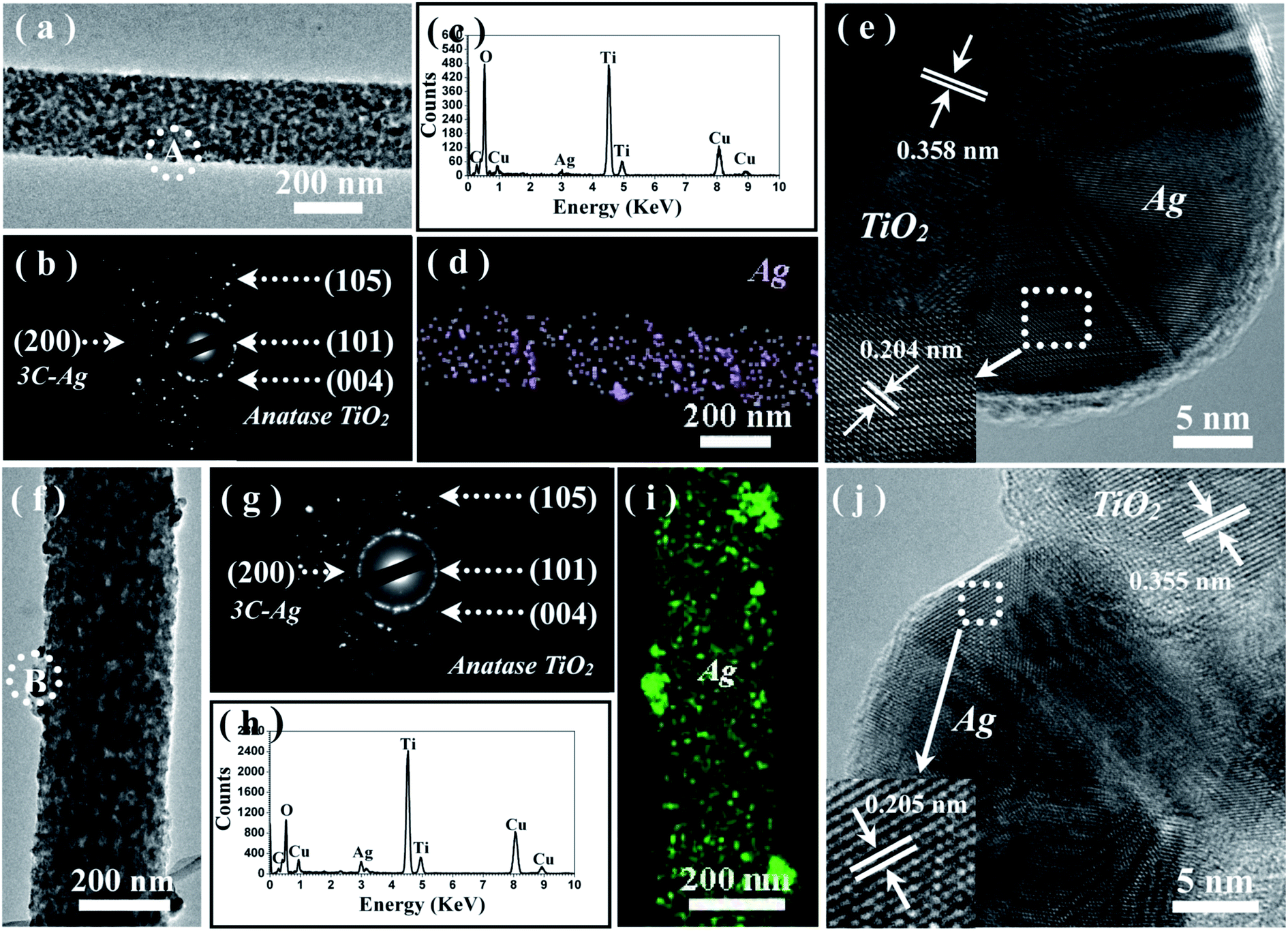 | ||
| Fig. 4 (a–e) TEM characterization of the Ag@TiO2 mesoporous nanofibers of sample A including: TEM image under a lower magnification (a); the corresponding SAED pattern (b); a typical EDS spectrum recorded from a single nanofiber (c); the element mapping of Ag within a single nanofiber under STEM-EDX (d); a representative HRTEM image (e) recorded from the marked area of A in (a). (f–j) TEM characterization of the Ag@TiO2 mesoporous nanofibers of sample B including: TEM image under a lower magnification (f); the corresponding SAED pattern (g); a typical EDS spectrum recorded from the single nanofiber (h); the element mapping of Ag within a single nanofiber under STEM-EDX (i); a representative HRTEM image (j) recorded from the marked area of A. | ||
Fig. 5 shows nitrogen adsorption–desorption isotherms and corresponding pore size distribution curves (inset) of Ag@TiO2 composite samples fabricated using the two different strategies and of pure TiO2 nanofibers. Both samples exhibit type IV adsorption isotherms with hysteresis loops according to BDDT classification, showing typical characteristics of mesoporous materials (2–50 nm).47,48 The surface textural properties all as-prepared sample products are summarized in Table 1. The results reveal that pure TiO2 products have higher BET surface area (61.7 m2 g−1) than Ag loaded samples (39.8 and 21.6 m2 g−1), suggesting that Ag loading can influence the BET surface area. This could be explained by Ag nanoparticles coating the TiO2 surface and blocking part of the pore channel to lower the adsorption capacity. The BET surface area and pore volume of Ag loaded TiO2 sample B is lowest compared with the others, which could be explained by attraction of Ag nanoparticles of big size and mass value.
 | ||
| Fig. 5 N2 adsorption and desorption isotherm of unloaded TiO2 mesoporous nanofibers and Ag loaded samples. The inset is the corresponding pore size distribution of the three products. | ||
| Samples | SBETa (m2 g−1) | Pore volumeb (cm3 g−1) | Average pore sizeb (nm) |
|---|---|---|---|
| a The BET specific surface area was determined by multipoint BET method using the adsorption data.b Pore volume and average pore size were determined by nitrogen adsorption volume. | |||
| Unloaded | 61.7 | 0.14 | 12.5 |
| Ag loaded sample A | 39.8 | 0.15 | 20.4 |
| Ag loaded sample B | 21.6 | 0.08 | 15.6 |
The elemental compositions and chemical status of the resulting samples were further ascertained by analyzing X-ray photoelectron spectroscopy (XPS). Fig. 6(a) shows the representative XPS survey spectra of pure TiO2 and Ag@ TiO2 samples prepared via the two different strategies, revealing that Ti, O, and C elements exist on the surface of the unloaded sample, while Ti, O, Ag, and C elements exist on the surface of the Ag loaded samples. The high resolution XPS spectra of Ag 3d, Ti2p, O 1s, and C 1s are displayed in Fig. 6(b–e). As observed in the Ag 3d spectra (Fig. 6(b)), two individual peaks were located at ca. 367.8 eV and ca. 373.7 eV for sample A, but at ca. 368.2 eV and ca. 374.2 eV for sample B, which can be assigned to Ag 3d3/2 and Ag 3d5/2 binding energies, respectively, being indicative of the characteristic of metallic silver (Ag0).49 In addition, the detected Ag 3d peaks of sample A have largely negative shifts compared with those of bulk Ag (368.3 eV for 3d5/2 and 374.3 eV for 3d3/2). These results indicate that electrons may migrate from TiO2 nanofibers to metallic Ag, and that there is a strong interaction between Ag particles and TiO2 support in the interface of nanoheterostructures. This may be of benefit to the photocatalysis process. The Ti 2p high-resolution spectrum of the pure TiO2 mesoporous nanofibers (the bottom spectrum of Fig. 6(c)) shows peaks at ca. 458.4 and ca. 464.0 eV corresponding to Ti 2p3/2 and Ti 2p1/2, respectively, suggesting the existence of a Ti4+ oxidation state.50 However, the bands were broad and shifted to higher binding energies when Ag was introduced (the middle and top spectra in Fig. 6(c)). These slight changes may be ascribed to the presence of Ti3+ oxide, except for the Ti4+ species of the Ag@TiO2 nanoheterostructures.51 Significantly, Ti3+ is known to have greater photocatalytic activity than Ti4+ owing to its special defect states favoring visible-light response.52 Fig. 6(d) shows high-resolution XPS spectra of O 1s in the pure TiO2 and Ag@TiO2 samples. The three spectra exhibit two characteristic peaks located at binding energies of ca. 529.7 and 531.9 eV, which are assigned to the Ti–O and hydroxyl species, respectively. The presence of C 1s in all three samples (Fig. 6(e)) can be ascribed to adventitious carbon-based contaminant from the XPS instrument itself.
 | ||
| Fig. 6 XPS survey spectrum (a) and high-resolution XPS spectrum of Ag 3d (b), Ti 2p (c), O 1s (d) and C 1s (e) of the Ag loaded samples and unloaded TiO2 mesoporous nanofibers for comparison. | ||
The UV-visible absorption spectra were used to track accurately the change of light absorbance characteristics in the as-prepared mesoporous nanofibers. As depicted in Fig. 7(a), there is only a steep absorption edge at the UV region and scarcely absorption in the visible-light region for the pure TiO2 sample. However, after attachment of Ag nanoparticles on the surface of TiO2 mesoporous nanofibers, the composites exhibit an additional broad absorption band at 400–800 nm, indicating that absorption of Ag@TiO2 nanoheterostructures significantly extends to the visible light wavelength range. Moreover, there is no obvious shift in the UV-vis absorption spectra, suggesting that silver deposition and synthesis strategy do not impact on the band gap.
 | ||
| Fig. 7 (a) UV-vis diffuse reflectance absorption spectra of the as-synthesized Ag@TiO2 mesoporous nanofibers and unloaded TiO2 mesoporous products. (b) Hydrogen production photocatalysed by the as-fabricated Ag@TiO2 mesoporous nanofibers and unloaded TiO2 samples under different irradiation time. (c) Dependence of the TBOT concentration on the photocatalytic activity of resultant TiO2 nanostructures for hydrogen evolution. | ||
The photocatalytic activity of the as-prepared products for hydrogen evolution was studied using methanol as sacrificial agent with irradiation under a 300 W xenon arc lamp. Fig. 7(b) plots the amount of hydrogen evolved from the aqueous suspensions over the three mesoporous nanofibers and the corresponding average hydrogen production rate is depicted in Fig. 7(c). It is noticeable that the hydrogen evolution rate of the pure TiO2 mesoporous sample (ca. 125.1 μmol g−1 h−1) is lower than those of the Ag loaded products (ca. 531.9 μmol g−1 h−1 and 257.6 μmol g−1 h−1), suggesting that introduction of the Ag nanoparticles resulted in significant improvement of the photocatalytic activity of TiO2. More interestingly, the hydrogen production rate of Ag loaded TiO2 mesoporous nanofibers is higher than reported values of other noble metal and transition metal loaded TiO2 nanocomposites (see Table S2, ESI†). In addition, the hydrogen production rate of the present mesoporous TiO2 nanofibers is higher than those of other reported TiO2 nanostructures, such as nanoparticles and normal solid nanofibers. This could be attributed to the unique 1D nanostructure and thorough porous fiber framework, which could provide the ideal photocatalyst platform.19 To account for the enhanced photocatalytic ability of the Ag@TiO2 heterostructured system, a proposed schematic diagram is illustrated in Fig. 8. According to the semiconductor photocatalysis theory, the TiO2 photocatalyst is induced by absorbed solar energy to create negative-electron (e−) charge and positive-hole (h+) charge pairs – this is referred to the “photo-excited” state.8 Afterwards, the excited electrons and holes act as reducing agent and oxidizing agent to produce H2 and O2, respectively, in the photocatalytic water-splitting reaction. However, most of the excited charges are recombined very rapidly and TiO2 can only absorb UV light because of its wide band gap (3.2 eV), which greatly affects its photocatalysis behavior. Taking this into consideration, the desired modification should help to avoid electron/hole recombination and absorb as much light as possible. Presently, the Ag@TiO2 photocatalysis can favor these demands with high efficiency, which can be explained as follows: (i) The Fermi level of Ag is lower than anatase TiO2 and a Schottky barrier can form between the Ag and TiO2 interface, which could serve as an efficient electron trap, thus preventing photoexcited electron–hole recombination; (ii) the strong interaction between Ag and TiO2, as revealed by the XPS results, leads to production of Ti3+ species on the surface and excites TiO2 under visible illumination. This means that the Ag@TiO2 photocatalysis can absorb more light energy under the same illumination.37,53,54 The Ag@TiO2 mesoporous photocatalysis of sample A showed more prominent performance than sample B, although the loaded Ag amount was less. This can be ascribed to the relation of BET surface area and the size of the loaded Ag nanoparticles, which can affect adsorption capacity and synergistic effect of the composites. For Ag loaded sample B, the superfluous Ag nanoparticles coated on the surface of TiO2 reduce its BET surface area and the size of the attached Ag nanoparticles is bulky, resulting in lower photocatalytic activity. Ag loaded sample A has more appropriately sized Ag nanoparticles and the higher BET surface area ensures the effect for nanosized Ag particles. Consequently, synthetic strategy I appears more valuable in highlighting the importance of designing semiconductor–metal 1D mesoporous heterostructures for advanced applications in photocatalysts and other light energy harvesting applications.
 | ||
| Fig. 8 Schematic diagram illustrating the possible photocatalytic mechanism of the Ag@TiO2 mesoporous nanofibers under xenon lamp irradiation. | ||
4. Conclusions
In summary, two strategies were demonstrated for preparing Ag@TiO2 mesoporous nanofibers. Incorporating Ag nanoparticles into the mesoporous 1D TiO2 nanofibers significantly enhances their photocatalytic activities, mainly attributed to formation of a Schottky barrier between the TiO2 and Ag species. In particular, Ag@TiO2 mesoporous nanofibers fabricated by in situ electrospinning exhibit the highest photocatalytic H2-production rate (531.9 μmol g−1 h−1), because of their higher BET surface area and smaller loaded Ag nanoparticles. The current work advances exploration into inexpensive and environmentally benign hybrid photocatalysts, which have potential applications in efficient photocatalysts for hydrogen evolution.Acknowledgements
This work was supported by National Natural Science Foundation of China (NSFC, Grant no. 51372122, 51372123, 51572133 and 51602163), Zhejiang Provincial Science Foundation (Grant no. LQ17E020002) and Natural Science Foundation of Ningbo Municipal Government (Grant no. 2016A610102).References
- G. Deluga, J. Salge, L. Schmidt and X. Verykios, Science, 2004, 303, 993–997 CrossRef CAS PubMed.
- J. Turner, G. Sverdrup, M. K. Mann, P. C. Maness, B. Kroposki, M. Ghirardi, R. J. Evans and D. Blake, Int. J. Energy Res., 2008, 32, 379–407 CrossRef CAS.
- K. Maeda, K. Teramura, D. Lu, T. Takata, N. Saito, Y. Inoue and K. Domen, Nature, 2006, 440, 295 CrossRef CAS PubMed.
- X. Wang, K. Maeda, A. Thomas, K. Takanabe, G. Xin, J. M. Carlsson, K. Domen and M. Antonietti, Nat. Mater., 2009, 8, 76–80 CrossRef CAS PubMed.
- Y. Tachibana, L. Vayssieres and J. R. Durrant, Nat. Photonics, 2012, 6, 511–518 CrossRef CAS.
- G. Liu, G. Zhao, W. Zhou, Y. Liu, H. Pang, H. Zhang, D. Hao, X. Meng, P. Li, T. Kako and J. Ye, Adv. Funct. Mater., 2016, 26, 6822–6829 CrossRef CAS.
- A. Fujishima, nature, 1972, 238, 37–38 CrossRef CAS PubMed.
- X. Chen, S. Shen and L. Guo, Chem. Rev., 2010, 110, 6503–6570 CrossRef CAS PubMed.
- Q. Xiang, J. Yu and M. Jaroniec, Chem. Soc. Rev., 2012, 41, 782–796 RSC.
- D. Yang, H. Liu, Z. Zheng, Y. Yuan, J.-C. Zhao, E. R. Waclawik, X. Ke and H. Zhu, J. Am. Chem. Soc., 2009, 131, 17885–17893 CrossRef CAS PubMed.
- T. Hisatomi, J. Kubota and K. Domen, Chem. Soc. Rev., 2014, 43, 7520–7535 RSC.
- B. Kenens, M. Chamtouri, R. Aubert, K. Miyakawa, Y. Hayasaka, H. Naiki and A. Masuhara, RSC Adv., 2016, 6, 97464–97468 RSC.
- G. L. Chiarello, A. Zuliani, D. Ceresoli, R. Martinazzo and E. Selli, ACS Catal., 2016, 6, 1345–1353 CrossRef CAS.
- A. L. Linsebigler, G. Lu and J. T. Yates Jr, Chem. Rev., 1995, 95, 735–758 CrossRef CAS.
- H. Tong, S. Ouyang, Y. Bi, N. Umezawa, M. Oshikiri and J. Ye, Adv. Mater., 2012, 24, 229–251 CrossRef CAS PubMed.
- X. Chen and S. S. Mao, Chem. Rev., 2007, 107, 2891–2959 CrossRef CAS PubMed.
- R. Daghrir, P. Drogui and D. Robert, Ind. Eng. Chem. Res., 2013, 52, 3581–3599 CrossRef CAS.
- S. Sun, P. Gao, Y. Yang, P. Yang, Y. Chen and Y. Wang, ACS Appl. Mater. Interfaces, 2016, 8, 18126–18131 CAS.
- S. K. Choi, S. Kim, S. K. Lim and H. Park, J. Phys. Chem. C, 2010, 2891 Search PubMed.
- X. Zhang, V. Thavasi, S. Mhaisalkar and S. Ramakrishna, Nanoscale, 2012, 4, 1707–1716 RSC.
- H. Hou, M. Shang, F. Gao, L. Wang, Q. Liu, J. Zheng, Z. Yang and W. Yang, ACS Appl. Mater. Interfaces, 2016, 8, 20128–20137 CAS.
- F. Dong, W. Zhao and Z. Wu, Nanotechnology, 2008, 19, 365607 CrossRef PubMed.
- A. Di Paola, G. Marci, L. Palmisano, M. Schiavello, K. Uosaki, S. Ikeda and B. Ohtani, J. Phys. Chem. B, 2002, 106, 637–645 CrossRef CAS.
- T. Montini, V. Gombac, L. Sordelli, J. J. Delgado, X. Chen, G. Adami and P. Fornasiero, ChemCatChem, 2011, 3, 574–577 CrossRef CAS.
- H.-I. Kim, J. Kim, W. Kim and W. Choi, J. Phys. Chem. C, 2011, 115, 9797–9805 CAS.
- K. E. deKrafft, C. Wang and W. Lin, Adv. Mater., 2012, 24, 2014–2018 CrossRef CAS PubMed.
- T. Hirakawa and P. V. Kamat, J. Am. Chem. Soc., 2005, 127, 3928–3934 CrossRef CAS PubMed.
- S. Kim, S.-J. Hwang and W. Choi, J. Phys. Chem. B, 2005, 109, 24260–24267 CrossRef CAS PubMed.
- H. Li, Z. Bian, J. Zhu, Y. Huo, H. Li and Y. Lu, J. Am. Chem. Soc., 2007, 129, 4538–4539 CrossRef CAS PubMed.
- L. Liu, Z. Liu, H. Bai and D. D. Sun, Water Res., 2012, 46, 1101–1112 CrossRef CAS PubMed.
- M. M. Khan, S. A. Ansari, M. I. Amal, J. Lee and M. H. Cho, Nanoscale, 2013, 5, 4427–4435 RSC.
- M. J. Nalbandian, M. Zhang, J. Sanchez, S. Kim, Y.-H. Choa, D. M. Cwiertny and N. V. Myung, J. Hazard. Mater., 2015, 299, 141–148 CrossRef CAS PubMed.
- Y.-C. Yao, X.-R. Dai, X.-Y. Hu, S.-Z. Huang and Z. Jin, Appl. Surf. Sci., 2016, 387, 469–476 CrossRef CAS.
- M. Z. Ge, C. Y. Cao, S. H. Li, Y. X. Tang, L. N. Wang, N. Qi and Y. K. Lai, Nanoscale, 2016, 8, 5226–5234 RSC.
- B. Xin, L. Jing, Z. Ren, B. Wang and H. Fu, J. Phys. Chem. B, 2005, 109, 2805–2809 CrossRef CAS PubMed.
- X. Wang, G. I. Waterhouse, D. R. Mitchell, K. Prince and R. A. Caruso, ChemCatChem, 2011, 3, 1763–1771 CrossRef CAS.
- N. Feng, Q. Wang, A. Zheng, Z. Zhang, J. Fan, S. B. Liu, J. P. Amoureux and F. Deng, J. Am. Chem. Soc., 2013, 135, 1607–1616 CrossRef CAS PubMed.
- M. Inagaki, Y. Yang and F. Kang, Adv. Mater., 2012, 24, 2547–2566 CrossRef CAS PubMed.
- C. Niu, J. Meng, X. Wang, C. Han, M. Yan, K. Zhao, X. Xu, W. Ren, Y. Zhao, L. Xu, Q. Zhang, D. Zhao and L. Mai, Nat. Commun., 2015, 6, 7402 CrossRef PubMed.
- S. An, H. S. Jo, D.-Y. Kim, H. J. Lee, B.-K. Ju, S. S. Al-Deyab, J.-H. Ahn, Y. Qin, M. T. Swihart, A. L. Yarin and S. S. Yoon, Adv. Mater., 2016, 28, 7149–7154 CrossRef CAS PubMed.
- C. Yuan, S. Guo, J. Song, C. Huo, Y. Li, B. Cui and X. Zhang, RSC Adv., 2017, 7, 4830–4839 RSC.
- S. H. Nam, H. S. Shim, Y. S. Kim, M. A. Dar, J. G. Kim and W. B. Kim, ACS Appl. Mater. Interfaces, 2010, 2, 2046–2052 CAS.
- Z. Zhang, Z. Wang, S. W. Cao and C. Xue, J. Phys. Chem. C, 2013, 117, 25939–25947 CAS.
- Z. Zhang, S. W. Cao, Y. Liao and C. Xue, Appl. Catal., B, 2015, 162, 204–209 CrossRef CAS.
- Z. Yang, J. Lu, W. Ye, C. Yu and Y. Chang, Appl. Surf. Sci., 2017, 392, 472–480 CrossRef CAS.
- H. Hou, L. Wang, F. Gao, G. Wei, B. Tang, W. Yang and T. Wu, J. Am. Chem. Soc., 2014, 136, 16716–16719 CrossRef CAS PubMed.
- P. Yang, D. Zhao, D. I. Margolese, B. F. Chmelka and G. D. Stucky, Nature, 1998, 396, 152–155 CrossRef CAS.
- M. Wang, Z. Sun, Q. Yue, J. Yang, X. Wang, Y. Deng, C. Yu and D. Zhao, J. Am. Chem. Soc., 2014, 136, 1884–1992 CrossRef CAS PubMed.
- C. Wagner and G. Muilenberg, Handbook of X-ray photoelectron spectroscopy, Perkin-Elmer, 1979 Search PubMed.
- Z. Song, J. Hrbek and R. Osgood, Nano Lett., 2005, 5, 1327–1332 CrossRef CAS PubMed.
- W. Grünert, A. Brückner, H. Hofmeister and P. Claus, J. Phys. Chem. B, 2004, 108, 5709–5717 CrossRef.
- F. Zuo, L. Wang, T. Wu, Z. Zhang, D. Borchardt and P. Feng, J. Am. Chem. Soc., 2010, 132, 11856–11857 CrossRef CAS PubMed.
- Y. Wang, L. Liu, L. Xu, C. Meng and W. Zhu, J. Appl. Phys., 2013, 113, 174311 CrossRef.
- D. Yang, Y. Sun, Z. Tong, Y. Tian, Y. Li and Z. Jiang, J. Phys. Chem. C, 2015, 119, 5827–5835 CAS.
Footnote |
| † Electronic supplementary information (ESI) available: TEM images of the obtained pure TiO2 mesoporous nanofibers and Ag loaded samples. See DOI: 10.1039/c7ra03177g |
| This journal is © The Royal Society of Chemistry 2017 |