
 Open Access Article
 This Open Access Article is licensed under a
 Creative Commons Attribution 3.0 Unported Licence
Generation of radical species in CVD grown pristine and N-doped solid carbon spheres using H2 and Ar as carrier gases†
Bridget K. Mutuma a,
Boitumelo J. Matsosoa,
Kamalakannan Ranganathana,
Jonathan M. Keartlandb,
Daniel Wamwangib and
Neil J. Coville*a
a,
Boitumelo J. Matsosoa,
Kamalakannan Ranganathana,
Jonathan M. Keartlandb,
Daniel Wamwangib and
Neil J. Coville*a
aDST-NRF Centre of Excellence in Strong Materials and Molecular Sciences Institute, School of Chemistry, University of the Witwatersrand, WITS 2050, Johannesburg, South Africa. E-mail: neil.coville@wits.ac.za; Fax: +27 11717 6749
bDST-NRF Centre of Excellence in Strong Materials and Materials Physics Research Institute, School of Physics, University of the Witwatersrand, WITS 2050, Johannesburg, South Africa
First published on 13th April 2017
Abstract
Solid carbon spheres (CSs, d ≈ 200 nm) were synthesized (yield, <40%) in a vertically oriented chemical vapor deposition (CVD) reactor using acetylene as a carbon source and Ar or H2 as the carrier gas. The CSs synthesized in the presence of H2 exhibited a broader thermal gravimetric derivative curve and a narrower paramagnetic signal than the CSs synthesized in Ar. Post synthesis doping of both types of CSs with nitrogen was achieved by passing acetonitrile at 800 °C for 1 h over the CSs in a CVD reactor. The N-doped CSs (NCSs) synthesized under both H2 and Ar displayed an increase in ID/IG ratios as obtained from Raman spectroscopy and showed an increase in the paramagnetic signal due to the presence of nitrogen induced defects compared to the undoped CSs. The NCSs synthesized in H2 had less graphitic-N (22%) than those produced in Ar (50%). The presence of a higher percentage of pyridinic-N and pyrrolic-N for the NCSs prepared with H2 as carrier gas suggested H2 etching effects on the CSs. Further, the N-doped carbon spheres obtained in the presence of H2 gave a higher N/C ratio (5.0) than in the presence of Ar (3.7). The introduction of edge defects and paramagnetic centers in CSs in the presence of H2 gas without the aid of a metal catalyst opens up a platform for regulating surface and catalytic reactions of CSs.
1. Introduction
Interest in carbon based nanomaterials continues to grow since the notable reports on fullerenes1 and carbon nanotubes.2 In the past two decades since these reports, routes to the synthesis of many new carbon materials have been developed. This includes the well-known carbon spheres (CSs), also known as carbon spherules3,4 carbon nanoballs5 carbon beads,6 carbon pearls7 and carbon microspheres which has been synthesized by various methods such as, spray pyrolysis, autoclave methods and chemical vapor deposition (CVD).4,8–10 The CVD synthesis route in particular provides a high quality and reproducible method to make CSs using readily available carbon sources.11 The synthesis of carbon nano/microspheres, unlike the synthesis of carbon nanotubes, requires no metal catalysts.12 Thus, a vertically oriented CVD reactor can be used to make CSs, and this results in the carbon spheres spending a very short time in the reactor, leading to the production of small sized carbon spheres (<300 nm in diameter).13 In contrast, the application of a horizontal reactor results in the production of larger and more graphitized carbon nanospheres due to a longer time the spheres remain in the reactor.14,15Numerous literature reports highlight the effect of the carbon source and the carrier gas on the growth dynamics of carbon nanomaterials using the CVD technique.16 To be specific, Lee et al. reported a decrease in the CNT aspect ratio formed from plasma enhanced CVD synthesis using acetylene (C2H2) as a carbon source due to etching of carbon atoms by hydrogen radicals.17 Similar hydrogen etching effects have been reported for MWCNTs, boron nitride and graphene sheets.18,19 Further, hydrogen gas plays a significant role in the growth and kinetics of graphene formation through dissociative hydrogen chemisorption and methane dehydrogenation chemisorption reactions.20 The hydrogenation of graphene and single walled carbon nanotubes (SWCNTs) has been reported to modulate the electronic and adsorption properties of the SWCNTs such as the band gap21 and their ability to store hydrogen.22 Recently, Zhao and co-workers23 reported on the improvement of electrochemical properties of carbon nanospheres upon hydrogenation that resulted in the conversion of sp2 carbons to sp3 hybridized carbons. The presence of hydrogen (via C–H bonds) readily led to bonding with metallic atoms such as lithium in lithium ion batteries. This enhanced the electrochemical reactivity23 of the battery. Not only does hydrogen influence the sp2/sp3 ratio and the electrochemical reactivity of carbon nanomaterials, it also impacts on the mechanical,24,25 electronic21 and optical21,26 properties of carbon nanomaterials. Carbon spheres are known to comprise of a mixture of sp2 and sp3 hybridized carbons and with a variable number of defects.27,28 The H2 etching effect is known to create edge defects and “dangling bonds” within a carbon based material such as the CSs, thus influencing their paramagnetic properties.27 These defects can lead to the presence of an unpaired electron (a paramagnetic centre) giving rise to a paramagnetic signal within a carbonaceous material which can be detected using electron spin resonance (ESR) spectroscopy.
The paramagnetic properties of undoped carbon nanomaterials are known to result from the localized edge states and the presence of defects29,30 and the effects can be enhanced by heteroatom doping with nitrogen or boron.31,32 It has been observed that, doping of carbon spheres with nitrogen increases the reactivity of carbons. This in turn enhances the applicability of carbon materials in dye sensitized solar cells,33 in oxygen reduction34 and in electronic devices.13 The nitrogen containing nanomaterials can be obtained by in situ doping or post doping.35–38 The in situ N-doping method can occur during chemical vapor deposition39,40 or by the pyrolysis41 of nitrogen containing compounds. On the other hand, post N-doping entails the annealing of pristine carbon materials at high temperatures in the presence of an atmosphere containing nitrogen species such as ammonia42 or acetonitrile.37,43 The degree of N-doping of carbon spheres depends on the concentration of the nitrogen source, the temperature and the reaction time.31,32 The degree of N-doping and type of N configuration influences the electronic, catalytic and magnetic properties of carbon.31,32,44,45 For instance, Guo et al.45 reported on a high oxygen reduction reactivity of N-doped carbon due to the creation of Lewis basic sites by the carbon atoms adjacent to a pyridinic-N bonding configuration. Similarly, Ombaka et al.46 attributed the selectivity for hydrogenation of nitrobenzophenone to aminobenzophenone to the promotion effect of the pyrrolic-N configuration in N-doped CNTs. In our previous work, Matsoso et al.40 reported a decrease in nitrogen content with the growth time of in situ N-doped graphene via an atmospheric pressure CVD method. At a shorter growth time, the N-doped graphene had a high ID/IG ratio and high number of edge defects that resulted in a high percentage of pyridinic-N being formed in the graphene. It is well known that the electronic properties of N-doped carbons is influenced by the sp2 hybridized carbon as well as the number of dangling bonds created in hydrogen terminated carbons.47
In literature, reports on the effect of hydrogenation on sp2/sp3 ratios have been determined for carbon nanospheres23 and on the paramagnetic properties of amorphous carbon thin films.27 However, the synthesis methods reported involve the use of harsh and tedious laboratory conditions such as autoclave method using potassium metal as a reductant or more costly synthesis routes such as solution plasma or plasma CVD processes. In this work, we report on the role of carrier gas on the paramagnetic properties as well as the N-configuration of post N-doped carbon nanospheres using a simple cost effective atmospheric pressure chemical vapour deposition method to affect sp2/sp3 ratios.
In this study we have shown that the structural, thermal and paramagnetic properties of the carbon spheres can be modified by varying the carrier gas e.g. by use of a reducing gas (H2) or an inert gas (Ar). To date, a study of the effect of the carrier gas on the structural, thermal and paramagnetic properties of carbon spheres and their N-doped analogues has not been previously reported. The solid carbon spheres were synthesized in a vertically oriented chemical vapor deposition (CVD) reactor. The effect of using argon or hydrogen as carrier gas on the morphology, structural, thermal and paramagnetic properties of the carbon spheres was investigated using TEM, TGA as well as Raman and electron spin resonance (ESR) spectroscopy. The type of N-configuration was elucidated using X-ray photoelectron spectroscopy (XPS) analysis.
2. Experimental
2.1 Synthesis of pristine and N-doped carbon spheres
Acetylene (C2H2, Afrox, 99.99%) was used to make carbon spheres (CSs) and to study the effect of carrier gas on the particle size and carbon morphology of the CSs. The carrier gases used were Ar (Afrox, 99.9%) or H2 (Afrox, 99.98%) for the synthesis of the CSs. The furnace was set to 900 °C at a heating rate of 10 °C min−1 under an Ar atmosphere (Ar, 200 sccm). After the desired temperature was reached, the C2H2 flow valve was opened at a 200 sccm flow rate and C2H2 was pyrolyzed in the quartz reactor at 900 °C for 20 min. The C2H2 feed was then stopped and the reactor cooled under a continuous flow of Ar gas to ambient temperature. The product (39.0 ± 0.3% yield) was collected in a round bottomed flask at the bottom of the reactor. For comparison purposes, instead of argon, H2 (gas flow rate of 100 sccm) was also used for the synthesis of the CSs (28.5 ± 0.3% yield). This lower flow rate of H2 gas yielded CSs with diameters comparable to those obtained using Ar gas as described above. Both products were collected and purified by Soxhlet extraction 150 °C for 24 h using toluene as a solvent (Sigma Aldrich, 99.5%). The products were dried at 100 °C for 12 h and referred to as CSs-Ar and CSs-H2 for the CSs synthesized in Ar and H2, respectively. N-doped CSs were obtained by passing acetonitrile (Sigma Aldrich, 99.9%) over the already prepared and purified products from use of both Ar and H2 for 1 hour at 800 °C with Ar as a carrier gas in a horizontal CVD reactor. The products were referred to as NCSs-Ar and NCSs-H2, respectively.2.2 Characterization of the carbon spheres
The morphological features of the synthesized carbon spheres were ascertained by transmission electron microscopy (TEM) using a FEI Technai G2 spirit electron microscope operating at 120 kV. Raman spectroscopic analysis was done to determine the effect of the carrier gas source on the degree of graphitization of the CSs. The measurement was carried out at room temperature using a Jobin-Yvon T6400 micro-Raman spectrometer equipped with a liquid nitrogen cooled charge coupled device detector and a laser excitation wavelength of 514.5 nm. IR spectra were recorded on a Bruker Tensor 27 spectrometer using an ATR assembly and data are shown in Fig. S2.† The thermal stability of the carbon spheres was investigated by thermal gravimetric analysis (TGA) conjugated with a weight loss derivative curve (DTG) using a Perkin Elmer Pyris 1 TGA. In the experiment, about 10 mg of each sample was placed in a ceramic pan, placed in the instrument furnace, heated to 900 °C at a rate of 10 °C min−1 under air and the data collected. The chemical composition of the post synthesised N-doped CSs was determined by X-ray photoelectron spectroscopy (XPS, Thermo Fischer Scientific). Electron spin resonance (ESR) measurements were carried out at room temperature using a Bruker ESP300E X-band spectrometer operating in the frequency range of 9.4 to 9.8 GHz.3. Results and discussion
3.1 Morphology of the pristine and N-doped CSs
The effect of using different carrier gases (H2 and Ar) on the morphology of the CSs produced from C2H2 was investigated. Fig. 1 shows that the carbon spheres had a spherical morphology and were accreted in agreement with earlier reports in literature.48,49 For both CSs-Ar and CSs-H2, particle sizes of less than 200 nm diameters were obtained (Fig. 1a and c). This is attributed to the short residence time and low nucleation rate used in a vertical reactor.48 Typically, carbon spheres are formed by the decomposition of the acetylene into carbon atoms or dimers at high temperatures.50 The nucleation rate of carbon atoms can be increased by the presence of catalysts, an increase in temperature and/or the decomposition kinetics.48,51,52 Typically, increasing the flow rate of either the carbon source and/or the carrier gas decreases the overall dwell time of C2H2 and other carbon based precursors in the reactor. | ||
| Fig. 1 TEM images of carbon spheres obtained using two different carrier gases; (a) CSs-H2; (b) NCSs-H2; (c) CSs-Ar and (d) NCSs-Ar, respectively. | ||
Carbon spheres of similar diameters to those obtained at a higher flow rate of Ar gas were formed using H2 at a lower flow rate (Table 1). This can be attributed to the reducing effects of hydrogen. The hydrogen influences the decomposition of acetylene, resulting in smaller carbon spheres. They were also found to have a less spherical morphology.12,51 The postdoping of the CSs with acetonitrile, as expected, was found to lead to an increase in the CS diameter. However, as seen in Table 1 the use of H2 leads to a larger CS diameter compared to Ar. This can be attributed to the presence of defects on the carbon surface that act as nucleation sites for attachment of more carbon atoms after acetonitrile decomposition. Interestingly, the N-doped CSs synthesized in Ar had similar sizes as found for the pristine CSs and this is associated with the presence of fewer surface defects that resulted in the attachment of fewer carbon atoms on the carbon surface as also confirmed by TGA and Raman spectroscopy (see below).
| Material | Carrier gas (flow rates) | Acetylene (flow rate) | Particle size (nm) | |
|---|---|---|---|---|
| Pristine | N-doped | |||
| CSs-H2 | H2 (100 sccm) | 200 sccm | 186 ± 34 | 200 ± 44 |
| CSs-Ar | Ar (200 sccm) | 200 sccm | 186 ± 27 | 189 ± 20 |
3.2 Raman analysis of the pristine and N-doped CSs
Fig. 2a and b shows the position of the Raman D and G bands and the intensities of the pristine and N-doped CSs synthesized in the presence of H2 and Ar, respectively. In all cases, a strong D band was observed between ∼1331 cm−1 and ∼1354 cm−1 which is associated with the breathing mode of sp2 carbon atoms and the presence of defects in the carbon structure.53 The lower D peak wavenumbers (∼1331 cm−1) in the CSs-H2 can be attributed to the presence of lattice distortions and a decrease in the number of ordered aromatic rings within the carbon structure.54 The presence of a small shoulder (*) at ∼1180 cm−1 is characteristic of the presence of possible trans-polyacetylene segments at the surface of the CSs.55,56 This shoulder was more pronounced in the CSs synthesized in H2 than those obtained in Ar, correlating to the higher number of hydrogen induced defects. In addition, a G peak was observed between ∼1591 cm−1 and ∼1595 cm−1 which is due to the E2g mode of vibration of sp2 bonded carbon and bond stretching of sp2 atoms.54,57 All the synthesized carbon spheres had a moderate degree of graphitization as shown by their low ID/IG ratios (less than 1) (see Table 2). Furthermore, after post N-doping of the CSs the Raman spectra indicated that an increase in the ID/IG ratios occurred when compared to the pristine CSs (Table 2). This is attributed to the presence of further defects being formed in the carbon structure after nitrogen doping.58 A slight upshift of the G peak and a larger upshift of the D peak was observed in the NCSs-H2. This can be attributed to defects induced by nitrogen atoms that were incorporated within the carbon lattice.59 In contrast, a slight downshift of the G peak was observed for the NCSs-Ar, which can be attributed to the presence of sp3 bonded nitrogen57 as corroborated by the XPS data. The NCSs-H2 resulted in a higher defect concentration than NCSs-Ar as indicated by the ID/IG ratios (Table 2). | ||
| Fig. 2 Raman spectra of the pristine and N-doped CSs (a) synthesized in H2 and (b) synthesized in Ar, respectively. | ||
| Material | D band position (cm−1) | G band position (cm−1) | ID/IG ratio |
|---|---|---|---|
| CSs-H2 | 1333 | 1593 | 0.89 |
| NCSs-H2 | 1354 | 1595 | 1.02 |
| CSs-Ar | 1340 | 1595 | 0.88 |
| NCSs-Ar | 1331 | 1591 | 0.92 |
3.3 TGA and surface area analysis of the pristine and N-doped CSs
Fig. 3 shows the TGA derivative profiles of the CSs produced before and after doping with nitrogen. The onset decomposition temperature of the CSs-H2 was 530 °C with the derivative peak centered at 717 °C (Table S1†). The CSs-H2 spheres exhibited a broader first order derivative peak (Fig. 3a) than the CSs-Ar (Fig. 3b). This could be attributed to defects induced by hydrogen in the form of Csp3H (dissociation energy: 339 kJ mol−1) or Csp3H2 (444 kJ mol−1) in the CSs obtained using H2, as well as the presence of C–C (347–356 kJ mol−1) and C![[double bond, length as m-dash]](https://www.rsc.org/images/entities/char_e001.gif) C bonds (614 kJ mol−1). This could result in a modified carbon oxidation process due to the varying decomposition rates.60 In the NCSs-H2, three decomposition peaks centered at 453 °C, 560 °C and 593 °C were observed (Fig. 3a). The lower onset decomposition peaks can be attributed to the incorporation of N within the structure of the carbon spheres. Interestingly, the decomposition peak at lower temperatures (<495 °C) was not observed in the pristine CSs. This could be associated with the loss of amorphous carbon domains61 resulting from sp3 hybridized carbons and to nitrogen bonded to sp3 hybridized carbon formed from the new carbon layer. The decomposition peaks at higher temperatures (>520 °C) in the N-doped carbon spheres can be attributed to the structural disorder and defects brought about by the presence of N in the carbon lattice62–64 as confirmed by the high ID/IG ratio from the Raman data.
C bonds (614 kJ mol−1). This could result in a modified carbon oxidation process due to the varying decomposition rates.60 In the NCSs-H2, three decomposition peaks centered at 453 °C, 560 °C and 593 °C were observed (Fig. 3a). The lower onset decomposition peaks can be attributed to the incorporation of N within the structure of the carbon spheres. Interestingly, the decomposition peak at lower temperatures (<495 °C) was not observed in the pristine CSs. This could be associated with the loss of amorphous carbon domains61 resulting from sp3 hybridized carbons and to nitrogen bonded to sp3 hybridized carbon formed from the new carbon layer. The decomposition peaks at higher temperatures (>520 °C) in the N-doped carbon spheres can be attributed to the structural disorder and defects brought about by the presence of N in the carbon lattice62–64 as confirmed by the high ID/IG ratio from the Raman data.
 | ||
| Fig. 3 The TGA derivative weight profiles of the pristine and N-doped CSs; (a) synthesized in H2 and (b) synthesized in Ar, respectively. | ||
Fig. 3b shows the TGA derivative profiles of the CSs-Ar and NCSs-Ar obtained using argon as a carrier gas. The onset decomposition temperature of the CSs-Ar occurred at 505 °C with a derivative decomposition peak centered at 640 °C. When Ar was the carrier gas a sharper derivative peak was observed; corresponding to a more pure and uniform carbon material (Fig. 3b).14,65 The NCSs-Ar showed two decomposition peaks centered at 460 °C and 635 °C, respectively. The first decomposition peak can again be attributed to the loss of amorphous carbon domains61 resulting from sp3 hybridized carbons and to nitrogen induced defects within the carbon lattice.62–64 The second decomposition peak centered at 635 °C was higher than that observed in the N-doped CSs produced in the presence of H2 (593 °C); indicating a higher thermal stability and the presence of fewer edge defects, consistent with the Raman and XPS data (see below).
The hydrogen etching effects on the CSs could be expected to lead to a change in the surface area of CSs synthesized in H2 (Fig. S1†). Indeed the BET surface area of CSs-H2 (9.2 m2 g−1) was larger than that of the CSs-Ar (6.3 m2 g−1) (Table S2†). After post N-doping, the NCSs-H2 portrayed a similar surface area (7.2 m2 g−1) while the NCSs-Ar exhibited a slight increase in the surface area to 10.5 m2 g−1. The slight increase could be ascribed to the incorporation of a larger % of graphitic-N atoms within the carbon matrix similar to that reported by Mhlanga et al.66 after heating carbon spheres in N2 at 800 °C. In NCSs-H2, the decrease in BET surface area in comparison to the CSs-H2 could be attributed to the nucleation of carbon atoms on the defect sites created by H2.
3.4 XPS analysis of the N-doped CSs
The elemental composition (at%) of the N-doped CSs were determined from the integral peak areas of the XPS survey spectra (Table 3). It can be observed that the carbon content was higher in the carbon spheres synthesized in the presence of Ar. In contrast, the O content and the O/C ratios were higher in the carbon spheres synthesized in the presence of H2 (3.9 versus 2.5; Table 3). This could be attributed to the effect of hydrogen etching of the carbon spheres which led to the disruption of the carbon lattice, thus resulting in a lower carbon content and a higher oxygen content. The nitrogen content in the carbon spheres synthesized using H2 as a carrier gas was higher (5.0) than in the carbon spheres obtained using Ar (3.7). This different concentrations could be attributed to the presence of edge defects in carbon spheres and lattice distortion due to H2 etching when synthesized in the presence of H2 gas.| Samples | Elements | ||||
|---|---|---|---|---|---|
| C (at%) | N (at%) | O (at%) | N/C (at%) | O/C (at%) | |
| NCSs-H2 | 91.8 | 4.6 | 3.5 | 5.0 | 3.9 |
| NCSs-Ar | 94.2 | 3.5 | 2.3 | 3.7 | 2.5 |
The XPS spectra showing the chemical environment of the C, N and O atoms in N-doped carbon spheres are shown in Fig. 4. The XPS signal of C 1s was deconvoluted into four peaks. The binding energy region (≈285.0 eV) corresponds to the sp3 C–C bonds and the lower binding energy region (≈284.5 eV) corresponds to sp2 CC bonds close to that of graphite.67,68 This indicates that the carbon spheres comprised of sp2 and sp3 hybridized carbon. The sp2 CC bonds were observed at 284.6 eV and 284.3 eV in the carbon spheres synthesized in H2 and Ar, respectively (Fig. 4a and c). Two other peaks were seen at 285.6 eV and 287.0 eV in the N-doped CSs produced in H2. In the N-doped CSs synthesized in Ar, the two peaks appeared at 285.1 eV and 286.1 eV. Reddy et al.69 showed that the positions of these component peaks can be assigned to carbon bonded to nitrogen atoms (which are more electronegative70) forming sp2 CN and sp3 C–N bonding configurations, respectively. The peaks at higher binding energy of 286.7 eV and 288.1 eV can be attributed to the formation of C–O and O–CO/N–CO bonds from the oxygen at the edges of the carbon domains.59
 | ||
| Fig. 4 The XPS spectra of deconvoluted C 1s and N 1s peaks of N-doped CSs; (a and b) NCSs-H2 and (c and d) NCSs-Ar, respectively. | ||
The N 1s spectrum of the NCSs-H2 was deconvoluted into four component peaks centered at 398.6 eV, 399.8 eV, 400.9 eV and 402.3 eV, respectively (Fig. 4b). In the NCSs-Ar, these four component peaks were centered at 397.9 eV, 399.1 eV, 400.9 eV and 402.8 eV, respectively (Fig. 4d). These peaks were assigned to; (i) pyridinic-N at 397.9–398.6 eV, with the N atom contributing one electron to the π-system, (ii) pyrrolic-N at 399.1–399.8 eV with the N atom contributing two electrons to the π-system, (iii) graphitic-N (400.9–400.9 eV) with the N atom substituting the C atom in the graphitic structure37,71 and (iv) NOX due to oxygenation of pyridinic-N (>402 eV).70,72,73 The NCSs-H2 comprised of 48% pyridinic-N, 21% pyrrolic-N and 22% graphitic-N and 9% NOX. The high percentage of pyridinic-N and pyrrolic-N can be ascribed to the hydrogen induced edge defects.63,64
In contrast, the NCSs-Ar had 18% pyridinic-N, 20% pyrrolic-N and 50% graphitic-N and 12% NOX, respectively (Table 4). The high percentage of graphitic-N can be ascribed to the rearrangement of the carbon and nitrogen atoms within the carbon lattice during the postdoping process in the CSs obtained in the presence of Ar. The generation of a higher % of graphitic-N configuration (51%) in postdoped N-CNTs synthesized using argon as carrier gas has also been reported by Xiong et al.37 The slightly higher % of pyrrolic-N in N-doped CSs obtained in the presence of H2 than those obtained in Ar can be attributed to nitrogen bonded to sp3 hybridized carbon as corroborated by the TGA data. The NOX concentration in the N-doped CSs synthesized in the presence of Ar was higher (12.1%) than in those obtained in the presence of hydrogen (8.6%). This can be ascribed to the hydrogen defects on the edges of carbon spheres that would inhibit bonding of the carbon with oxygen when hydrogen gas was used as carrier gas.
| Samples | Peaks | |||
|---|---|---|---|---|
| Pyridinic-N (eV) | Pyrrolic-N (eV) | Graphitic-N (eV) | NOX (eV) | |
| NCSs-H2 | 48.4 | 20.7 | 22.3 | 8.6 |
| NCSs-Ar | 18.2 | 19.9 | 49.8 | 12.1 |
The effect of carrier gas on the N-configuration of the CSs can be rationalized as follows. During post doping of the CSs, acetonitrile decomposes at high temperatures to give propyl nitrile and other radicals.74 The radicals decompose further to give nitrogen atoms that are incorporated on the carbon nanostructure edges or in the matrix by substitutional doping. In the case of CSs obtained using H2, there exist defect sites which further reacts with the radicals generated by the acetonitrile decomposition resulting in incorporation of nitrogen on the edges. In contrast, in the CSs synthesized in argon, there are fewer C–H termination sites but instead a rearrangement occurs within the carbon matrix resulting in the N atoms substituting the carbon atoms.
3.5 The paramagnetic properties of the pristine and N-doped CSs
All four samples exhibited ESR spectra centered at g ≈ 2.000. ESR spectra of pristine and N-doped CSs showed Dysonian resonance curves indicating the presence of charge carriers75 (Fig. 5a–d). The recorded spectra were comparable to the data recorded for other pristine carbon spheres reported in the literature.76 The CSs-H2 showed a narrower line width (peak to peak distance, 0.54 ± 0.01 G) than that of the CSs-Ar (1.83 ± 0.01 G) (Table S2†). This can be attributed to the creation of localized electron spins77 resulting from dangling bonds and mid-gap state π bonds (Fig. 5a). It is well known that the paramagnetic centres are determined by the π-electrons in the sp2 bonded orbitals. Despite reports in literature that show that bonded-hydrogen give non-ESR active states, hydrogen can saturate the sp2 bonded orbitals to give Csp3H, Csp3H2 and Csp3H3 phases.78 These phases can create structural disorder in the carbon structure which increases the concentration of defects. The CSs synthesized in H2 exhibited a larger ESR signal intensity confirming the presence of a high concentration of defects79,80 as suggested by the Raman and TGA data. In contrast, for the CSs synthesized under Ar gas, a broader line width and a less intense paramagnetic resonance signal was observed (Fig. 5c). This can be ascribed to a presence of conducting charge carriers and delocalized electron spins resulting from the sp2 graphitized carbon.51,81,82 The broader line width in the CSs synthesized in Ar could be associated with a more pure carbon surface (less defects on surface carbon lattice)83 as suggested by TGA data.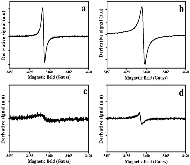 | ||
| Fig. 5 Electron spin resonance spectra of the pristine and N-doped CSs; (a) CSs-H2, (b) NCSs-H2, (c) NCSs-Ar and (d) NCSs-Ar, respectively. | ||
Fig. 5b and d shows the ESR spectra of the N-doped CSs. The ESR linewidth of the N-doped CSs synthesized in the presence of H2 was larger (0.78 ± 0.01) than that of the pristine CSs (0.54 ± 0.01) (Fig. 5b). This increase in linewidth can be attributed to a more disordered carbon84 due to N-induced defects in the sp2 graphitic units and edge induced defects as corroborated by the XPS data. In contrast, the ESR signal in the N-doped CSs synthesized in the presence of Ar had a much smaller linewidth (0.61 ± 0.01 G) than their pristine counterparts (1.83 ± 0.01 G). This could result from reorganization of carbons during the annealing process resulting in a stronger paramagnetic signal for the N-doped CSs.85 A broader line width of the N-doped CSs synthesized in H2 than that of the N-doped spheres synthesized in Ar can be associated with an increase in edge defects resulting from localized spins on the N-centered dangling bonds yielding a stronger ESR signal. Keartland et al.86 reported an ESR line width of 1.14 ± 0.01 G for nitrogen doped carbon spheres containing 3.52% N. Our calculated ESR line width for the NCSs-H2 was narrower (0.78) and this could be attributed to the presence of the higher N content (5.0). Thus, the higher the nitrogen content the more intense the paramagnetic signal and the narrower the linewidth.
3.6 Mechanism rationalizing the role of carrier gas on CS structure and N-configuration
Fig. 6 shows a possible mechanism to rationalize the role of the carrier gas (reducing versus inert) on the carbon sphere structure and the type of N-configurations formed in the reactions. Post synthesis N-doping of carbon materials can be viewed as a surface functionalization reaction to generate a core/shell structure (Fig. 6). The presence of hydrogen gas (a reducing atmosphere) during synthesis is known to etch the carbon atoms resulting in edge induced defects;79,80 as was detected in the XPS and ESR data. This resulted in the dominance of pyridinic-N and pyrrolic-N upon N-doping. However, due to the thermally stable carbon sphere core (Fig. 6a), less carbon atoms are replaced by the nitrogen resulting in a lower percentage of graphitic-N. The N-configuration induces N-centered dangling bonds and edge defects resulting in a stronger ESR signal as well as a higher O/C content. | ||
| Fig. 6 Possible mechanism showing the role of carrier gas on the N-configuration of the CSs synthesized in the presence of (a) H2 and (b) Ar, respectively. | ||
In contrast, when argon gas is used as a carrier gas, the carbon structure is composed of a pure carbon surface. Upon N-doping of the carbon spheres, the carbon atoms are directly replaced by nitrogen atoms leading to a higher percentage of graphitic-N (Fig. 6b). In contrast, argon being an inert gas induces fewer edge defects, thus, fewer pyridinic-N atoms are observed with a low percentage of O/C content. In summary, hydrogen causes modification of the carbon shell and etching leads to more defects and a more defective-NCSs (Fig. 6a).
This study provides insight on the significant role of carrier gas on the thermal, structural and paramagnetic properties of carbon spheres. We would anticipate that for possible application of carbon spheres in solar cells, a higher percentage of graphitic-N35 will be much favourable than that of pyridinic-N. However, for catalytic reactions, a higher percentage of pyridinic-N and pyrrolic-N is favourable due to their ability to create larger edge plane exposure.44,87,88 These ideas will be investigated in later studies.
4. Conclusions
Carbon spheres with small and homogeneous diameters of d ≈ 200 nm were synthesized by use of a high flow rate of the acetylene (200 sccm) and different carrier gases (Ar or H2) in a vertical CVD reactor. The CSs-H2 had more structural defects and a more intense paramagnetic signal due to hydrogen induced defects than found for CSs-Ar. The CSs-Ar had less structural defects and a smaller and a broader paramagnetic signal. Doping of the carbon spheres with N did result in an increase in ID/IG ratios due to the presence of further defects induced by N. In addition, the paramagnetic signal to noise ratio was stronger in the post N-doped CSs.All the N-doped CSs exhibited pyridinic, pyrrolic, graphitic nitrogen and NOX configurations. Post N-doping of carbon spheres synthesized in H2 resulted in higher compositions of pyridinic-N and pyrrolic-N, a low content of graphitic-N and an overall higher N % compared to the N-doped CSs obtained in Ar gas. The presence of edge defect states in the post N-doped CSs synthesized in the presence of H2 was confirmed by the higher percentage of pyridinic-N and pyrrolic-N configurations as seen from the XPS data.
This study clearly illustrates the effect of the carrier gas on the structural, thermal and paramagnetic properties of CVD grown solid CSs. The XPS and ESR data shows that the synthesis of carbon spheres in the presence of hydrogen creates more edge defects. Consequently the carrier gas used in the carbon synthesis plays a role in determining the type of N-configurations formed in the post N-doped CSs. This study opens a platform for the use of hydrogen as a carrier gas to induce open edge defects in carbon for application in surface reactions.
Acknowledgements
We thank the School of Chemistry, the NRF and the DST-NRF Centre of Excellence in Strong Materials for funding. We also acknowledge Mr Werner Jordaan at the National Metrology Institute of South Africa (NMISA), Pretoria for his assistance with the XPS analysis.References
- S. Iijima, Nature, 1991, 354, 56–58 CrossRef CAS.
- H. W. Kroto, J. R. Heath, S. C. O'Brien, R. F. Curl and R. E. Smalley, Nature, 1985, 318, 162–163 CrossRef CAS.
- Q. Wang, H. Li, L. Chen and X. Huang, Carbon, 2001, 39, 2211–2214 CrossRef CAS.
- V. G. Pol, M. Motiei, A. Gedanken, J. Calderon-Moreno and M. Yoshimura, Carbon, 2004, 42, 111–116 CrossRef CAS.
- A. A. Deshmukh, S. D. Mhlanga and N. J. Coville, Mater. Sci. Eng., R, 2010, 70, 1–28 CrossRef.
- M. Sharon, K. Mukhopadhyay, K. Yase, S. Iijima, Y. Ando and X. Zhao, Carbon, 1998, 36, 507–511 CrossRef CAS.
- L. P. Biró, G. I. Márk, Z. E. Horváth, K. Kertész, J. Gyulai, J. B. Nagy and P. Lambin, Carbon, 2004, 42, 2561–2566 CrossRef.
- G. Krishnamurthy, R. Namitha and S. Agarwal, Procedia Mater. Sci., 2014, 5, 1056–1065 CrossRef CAS.
- C. Chen, X. Sun, X. Jiang, D. Niu, A. Yu, Z. Liu and J. Li, Nanoscale Res. Lett., 2009, 4, 971–976 CrossRef CAS PubMed.
- M. W. Dlamini, D. O. Kumi, T. N. Phaahlamohlaka, A. S. Lyadov, D. G. Billing, L. L. Jewell and N. J. Coville, ChemCatChem, 2015, 7, 3000–3011 CrossRef CAS.
- J. Creighton and P. Ho, Chem. Vap. Deposition, 2001, 2, 1–22 CAS.
- H.-s. Qian, F.-m. Han, B. Zhang, Y.-c. Guo, J. Yue and B.-x. Peng, Carbon, 2004, 42, 761–766 CrossRef CAS.
- S. C. Ray, Z. N. Tetana, R. Erasmus, A. Mathur and N. J. Coville, Int. J. Energy Res., 2014, 38, 444–451 CrossRef CAS.
- G. E. J. Poinern, S. Brundavanam, M. Shah, I. Laava and D. Fawcett, Nanotechnol., Sci. Appl., 2012, 5, 49–59 CrossRef CAS PubMed.
- H. Xiong, M. A. M. Motchelaho, M. Moyo, L. L. Jewell and N. J. Coville, J. Catal., 2011, 278, 26–40 CrossRef CAS.
- S. D. Mhlanga, K. C. Mondal, N. Naidoo, N. Kunjuzwa, M. J. Witcomb and N. J. Coville, S. Afr. J. Sci., 2009, 105, 304–308 CAS.
- T. Young Lee, J.-H. Han, S. Hong Choi, J.-B. Yoo, C.-Y. Park, T. Jung, S. Yu, W. K. Yi, I. T. Han and J. M. Kim, Diamond Relat. Mater., 2003, 12, 851–855 CrossRef.
- M. J. Behr, E. A. Gaulding, K. A. Mkhoyan and E. S. Aydil, J. Vac. Sci. Technol., B: Microelectron. Nanometer Struct.--Process., Meas., Phenom., 2010, 28, 1187–1194 CAS.
- R. Zhang, T. Chu, C. S. Lee and S. T. Lee, Chem. Vap. Deposition, 2000, 6, 227–230 CrossRef CAS.
- M. Losurdo, M. M. Giangregorio, P. Capezzuto and G. Bruno, Phys. Chem. Chem. Phys., 2011, 13, 20836–20843 RSC.
- C.-Y. Liu, C.-F. Chen, J.-P. Leu, C.-C. Lu and K.-H. Liao, Sens. Actuators, B, 2009, 143, 12–16 CrossRef.
- A. Nikitin, H. Ogasawara, D. Mann, R. Denecke, Z. Zhang, H. Dai, K. Cho and A. Nilsson, Phys. Rev. Lett., 2005, 95, 225507 CrossRef CAS PubMed.
- S. Zhao, Y. Fan, K. Zhu, D. Zhang, W. Zhang, S. Chen, R. Liu, M. Yao and B. Liu, Nanoscale, 2015, 7, 1984–1993 RSC.
- N. Dwivedi, S. Kumar and H. K. Malik, Appl. Phys. Lett., 2013, 102, 011917 CrossRef.
- X. Li, Q. Xue, Z. Liu, C. Ling, Y. Tao and T. Wu, J. Phys. Chem. C, 2014, 118, 16087–16094 CAS.
- S. Pisana, S. K. O'Leary and S. Zukotynski, J. Non-Cryst. Solids, 2005, 351, 736–740 CrossRef CAS.
- M. Hoinkis, E. Tober, R. White and M. Crowder, Appl. Phys. Lett., 1992, 61, 2653–2655 CrossRef CAS.
- J. Walters and R. J. Newport, J. Phys.: Condens. Matter, 1995, 7, 1755 CrossRef CAS.
- E. G. Santos, A. Ayuela and D. Sánchez-Portal, in Topological Modelling of Nanostructures and Extended Systems, ed. A. R. Ashrafi, F. Cataldo, A. Iranmanesh and O. Ori, Springer, Netherlands, 2013, vol. 7, ch. 2, pp. 41–76 Search PubMed.
- A. V. Rode, E. G. Gamaly, A. G. Christy, J. G. Fitz Gerald, S. T. Hyde, R. G. Elliman, B. Luther-Davies, A. I. Veinger, J. Androulakis and J. Giapintzakis, Phys. Rev. B: Condens. Matter Mater. Phys., 2004, 70, 054407 CrossRef.
- C. N. R. Rao, K. Gopalakrishnan and A. Govindaraj, Nano Today, 2014, 9, 324–343 CrossRef CAS.
- P. Sun, K. Wang, J. Wei, M. Zhong, D. Wu and H. Zhu, Nano Res., 2014, 7, 1507–1518 CrossRef CAS.
- L. Wang, Z. Gao, J. Chang, X. Liu, D. Wu, F. Xu, Y. Guo and K. Jiang, ACS Appl. Mater. Interfaces, 2015, 7, 20234–20244 CAS.
- S. Gao, K. Geng, H. Liu, X. Wei, M. Zhang, P. Wang and J. Wang, Energy Environ. Sci., 2015, 8, 221–229 CAS.
- D. Wei, Y. Liu, Y. Wang, H. Zhang, L. Huang and G. Yu, Nano Lett., 2009, 9, 1752–1758 CrossRef CAS PubMed.
- F. R. García-García, J. Álvarez-Rodríguez, I. Rodríguez-Ramos and A. Guerrero-Ruiz, Carbon, 2010, 48, 267–276 CrossRef.
- H. Xiong, M. A. Motchelaho, M. Moyo, L. L. Jewell and N. J. Coville, Appl. Catal., A, 2014, 482, 377–386 CrossRef CAS.
- Z. Yang, Y. Xia, X. Sun and R. Mokaya, J. Phys. Chem. B, 2006, 110, 18424–18431 CrossRef CAS PubMed.
- H. Xiong, M. Moyo, M. A. Motchelaho, Z. N. Tetana, S. M. A. Dube, L. L. Jewell and N. J. Coville, J. Catal., 2014, 311, 80–87 CrossRef CAS.
- B. J. Matsoso, K. Ranganathan, B. K. Mutuma, T. Lerotholi, G. Jones and N. J. Coville, RSC Adv., 2016, 6, 106914–106920 RSC.
- B. Cao, H. Liu, Z. Xing, Y. Lei, H. Song, X. Chen, J. Zhou and Z. Ma, ACS Sustainable Chem. Eng., 2015, 3, 1786–1793 CrossRef CAS.
- H.-C. Wen, K. Yang, K.-L. Ou, W.-F. Wu, C.-P. Chou, R.-C. Luo and Y.-M. Chang, Surf. Coat. Technol., 2006, 200, 3166–3169 CrossRef CAS.
- Y. Xia, Z. Yang and R. Mokaya, J. Phys. Chem. B, 2004, 108, 19293–19298 CrossRef CAS.
- P. H. Matter, E. Wang, M. Arias, E. J. Biddinger and U. S. Ozkan, J. Phys. Chem. B, 2006, 110, 18374–18384 CrossRef CAS PubMed.
- D. Guo, R. Shibuya, C. Akiba, S. Saji, T. Kondo and J. Nakamura, Science, 2016, 351, 361–365 CrossRef CAS PubMed.
- L. M. Ombaka, P. G. Ndungu and V. O. Nyamori, RSC Adv., 2015, 5, 109–122 RSC.
- Y. Hayashi, G. Yu, M. Rahman, K. Krishna, T. Soga, T. Jimbo and M. Umeno, J. Appl. Phys., 2001, 89, 7924–7931 CrossRef CAS.
- Y. Z. Jin, C. Gao, W. K. Hsu, Y. Zhu, A. Huczko, M. Bystrzejewski, M. Roe, C. Y. Lee, S. Acquah, H. Kroto and D. R. M. Walton, Carbon, 2005, 43, 1944–1953 CrossRef CAS.
- Z. C. Kang and Z. L. Wang, J. Phys. Chem., 1996, 100, 5163–5165 CrossRef CAS.
- N. J. Coville, S. D. Mhlanga, E. N. Nxumalo and A. Shaikjee, S. Afr. J. Sci., 2011, 107, 01–15 Search PubMed.
- V. G. Pol, S. V. Pol, J. M. Calderon Moreno and A. Gedanken, Carbon, 2006, 44, 3285–3292 CrossRef CAS.
- Z. C. Kang and Z. L. Wang, Philosophical Magazine Part B, 1996, 73, 905–929 CrossRef CAS.
- A. C. Ferrari, Solid State Commun., 2007, 143, 47–57 CrossRef CAS.
- A. C. Ferrari and J. Robertson, Phys. Rev. B: Condens. Matter Mater. Phys., 2000, 61, 14095 CrossRef CAS.
- A. Ferrari and J. Robertson, Phys. Rev. B: Condens. Matter Mater. Phys., 2001, 63, 121405 CrossRef.
- T. Oshiro, M. Yamazato, A. Higa and M. Toguchi, Jpn. J. Appl. Phys., 2007, 46, 756 CrossRef CAS.
- F. Tuinstra and J. L. Koenig, J. Chem. Phys., 1970, 53, 1126–1130 CrossRef CAS.
- E. M. M. Ibrahim, V. O. Khavrus, A. Leonhardt, S. Hampel, S. Oswald, M. H. Rümmeli and B. Büchner, Diamond Relat. Mater., 2010, 19, 1199–1206 CrossRef CAS.
- N. Dwivedi, S. Kumar, J. Carey, H. K. Malik and Govind, J. Appl. Phys., 2012, 112, 113706 CrossRef.
- K. Nikiwe, Ph. D. thesis, University of the Witwatersrand, Johannesburg, 2009.
- C. Petit, K. Kante and T. J. Bandosz, Carbon, 2010, 48, 654–667 CrossRef CAS.
- X. Ma, E. Wang, W. Zhou, D. A. Jefferson, J. Chen, S. Deng, N. Xu and J. Yuan, Appl. Phys. Lett., 1999, 75, 3105–3107 CrossRef CAS.
- R. Kurt and A. Karimi, ChemPhysChem, 2001, 2, 388–392 CrossRef CAS PubMed.
- E. N. Nxumalo, P. J. Letsoalo, L. M. Cele and N. J. Coville, J. Organomet. Chem., 2010, 695, 2596–2602 CrossRef CAS.
- J.-Y. Miao, D. W. Hwang, C.-C. Chang, S.-H. Lin, K. V. Narasimhulu and L.-P. Hwang, Diamond Relat. Mater., 2003, 12, 1368–1372 CrossRef CAS.
- S. Mhlanga, N. Coville, S. Iyuke, A. Afolabi, A. Abdulkareem and N. Kunjuzwa, J. Exp. Nanosci., 2010, 5, 40–51 CrossRef CAS.
- P. Mérel, M. Tabbal, M. Chaker, S. Moisa and J. Margot, Appl. Surf. Sci., 1998, 136, 105–110 CrossRef.
- J. Diaz, G. Paolicelli, S. Ferrer and F. Comin, Phys. Rev. B: Condens. Matter Mater. Phys., 1996, 54, 8064 CrossRef CAS.
- A. L. M. Reddy, A. Srivastava, S. R. Gowda, H. Gullapalli, M. Dubey and P. M. Ajayan, ACS Nano, 2010, 4, 6337–6342 CrossRef CAS PubMed.
- E. J. Biddinger, D. von Deak and U. S. Ozkan, Top. Catal., 2009, 52, 1566–1574 CrossRef CAS.
- K. A. Grant, Q. Zhu and K. M. Thomas, Carbon, 1994, 32, 883–895 CrossRef CAS.
- Q. Zhu, S. L. Money, A. E. Russell and K. M. Thomas, Langmuir, 1997, 13, 2149–2157 CrossRef CAS.
- Y. F. Jia, B. Xiao and K. M. Thomas, Langmuir, 2002, 18, 470–478 CrossRef CAS.
- A. Lifshitz and C. Tamburu, Int. J. Chem. Kinet., 1998, 30, 341–347 CrossRef CAS.
- J. P. Joshi and S. V. Bhat, J. Magn. Reson., 2004, 168, 284–287 CrossRef CAS PubMed.
- V. G. Pol, Environ. Sci. Technol., 2010, 44, 4753–4759 CrossRef CAS PubMed.
- S. Rao, A. Stesmans, J. Noyen, P. Jacobs and B. Sels, J. Phys.: Condens. Matter, 2011, 23, 455801 CrossRef CAS PubMed.
- G. Fanchini, A. Tagliaferro, B. Popescu and E. Davis, J. Non-Cryst. Solids, 2002, 299, 846–851 CrossRef.
- J. Kombarakkaran and T. Pietraß, Chem. Phys. Lett., 2008, 452, 152–155 CrossRef CAS.
- W. D. Rice, R. T. Weber, A. D. Leonard, J. M. Tour, P. Nikolaev, S. Arepalli, V. Berka, A.-L. Tsai and J. Kono, ACS Nano, 2012, 6, 2165–2173 CrossRef CAS PubMed.
- J. M. Calderon Moreno, S. S. Swamy, T. Fujino and M. Yoshimura, Chem. Phys. Lett., 2000, 329, 317–322 CrossRef CAS.
- M. Chipara, F. Iacomi, J. Zaleski and J. Bai, J. Optoelectron. Adv. Mater., 2006, 8, 820 CAS.
- W. P. Wright, V. Marsicano, J. Keartland, R. Erasmus, S. Dube and N. Coville, Mater. Chem. Phys., 2014, 147, 908–914 CrossRef CAS.
- H. Zhang, S. Liu, A. Wei, Y. He, X. Tang, X. Xue, L. Liang and C. Wu, J. Phys. Chem. Solids, 2000, 61, 1123–1125 CrossRef CAS.
- V. G. Pol, J. M. Calderon-Moreno and P. Thiyagarajan, Ind. Eng. Chem. Res., 2009, 48, 5691–5695 CrossRef CAS.
- J. M. Keartland, M. B. Dubazane, V. D. Marsicano, N. Kunjuzwa and N. J. Coville, Proceedings of SA Institute of Physics, 2011, pp. 127–133, ISBN: 978-1-86888-688-3 Search PubMed.
- S. Maldonado and K. J. Stevenson, J. Phys. Chem. B, 2005, 109, 4707–4716 CrossRef CAS PubMed.
- P. H. Matter, E. Wang, M. Arias, E. J. Biddinger and U. S. Ozkan, J. Mol. Catal. A: Chem., 2007, 264, 73–81 CrossRef CAS.
Footnote |
| † Electronic supplementary information (ESI) available. See DOI: 10.1039/c7ra03142d |
| This journal is © The Royal Society of Chemistry 2017 |