
 Open Access Article
 This Open Access Article is licensed under a Creative Commons Attribution-Non Commercial 3.0 Unported Licence
Steam-assisted transformation of natural kaolin to hierarchical ZSM-11 using tetrabutylphosphonium hydroxide as structure-directing agent: synthesis, structural characterization and catalytic performance in the methanol-to-aromatics reaction†
Zhenhao Weia,
Kake Zhu a,
Lanyu Xinga,
Fan Yanga,
Yunsheng Lia,
Yarong Xub and
Xuedong Zhu*a
a,
Lanyu Xinga,
Fan Yanga,
Yunsheng Lia,
Yarong Xub and
Xuedong Zhu*a
aUNILAB, State Key Lab of Chemical Engineering, School of Chemical Engineering, East China University of Science and Technology, 130 Meilong Road, Shanghai 200237, China. E-mail: xdzhu@ecust.edu.cn; Fax: +86-21-64252386; Tel: +86-21-64252386
bResearch Institute of Urumchi Petrochemical Company, PetroChina Company Limited, Urumchi 830019, China
First published on 3rd May 2017
Abstract
Transforming natural kaolin into pure-phase hierarchical aggregates of nano ZSM-11 has been achieved by using a novel tetrabutylphosphonium hydroxide as a structure-directing agent via steam-assisted crystallization. The hierarchical ZSM-11 possesses a small particle size (about 240 nm), large surface area (428 m2 g−1), and abundant mesopores (0.30 cm3 g−1). Moreover, the hierarchical ZSM-11 exhibits prolonged catalytic lifetime and promoted aromatic selectivity in the methanol-to-aromatics reaction. The superior catalyst stability is attributed to the better capacity of accommodating the coke and a lowered coking rate.
1. Introduction
The methanol-to-aromatics (MTA) reaction is a promising process for achieving sustainable supplies of aromatics in the post-oil era.1,2 ZSM-5 is a frequently used catalyst for this transformation, owing to its high aromatic selectivity resulting from shape selectivity imparted by MFI topology. Recent studies have also shown that hierarchical or nanosized ZSM-5 often outperforms conventional ZSM-5 in the MTA reaction, and enhanced stability and selectivity have been observed as a result of mitigated diffusion restriction.1–3 ZSM-11, an MEL-type pentasil zeolite, has also been explored as a potential MTA catalyst, with the finding that a prolonged catalyst lifetime can be achieved.4 The advantage of hierarchical ZSM-11 in MTA and other reactions has inspired research efforts for their synthesis. Previously, hierarchical ZSM-11 zeolites were prepared by various methods, including desilication,5 carbon templating,6 and soft templating,7 to name but a few. However, these methods are costly, synthetically complicated, and environmentally unfriendly. For instance, expensive surfactants are required to control desilication of parent zeolites to generate mesopores. In carbon templating, large amounts of expensive carbon templates were consumed for the formation of mesopores. Furthermore, soft templating requires a two-step synthetic procedure to avoid phase separation, and the combustion of the templates results in dangerous emissions into the environment.Kaolin, an inexpensive natural mineral, has been increasingly used to replace aluminum- and silicon-containing chemicals as the precursor to synthesize various zeolites, such as A,8 Y,9 NaX,10 SAPO-34,11 mordenite12 and ZSM-5.13 To date, there are no reports on the synthesis of ZSM-11 from kaolin, to the best of our knowledge. Generally, kaolin-derived zeolites, prepared by conventional hydrothermal methods, exhibit micrometer-sized particles. Zhu et al. reported a facile method to prepare mesoporous ZSM-5 zeolites via a steam-assisted crystallization (SAC) method.14 When the method is extrapolated to synthesize ZSM-11, ZSM-5/11 intergrowth was achieved from natural kaolin using the conventional tetrabutylammonium hydroxide (TBAOH) as the structure-directing agent (SDA) via SAC (cf. Experimental and results in ESI†).
Recently, Tsapatsis et al. proposed the one-step synthesis of self-pillared pentasil (SPP) hierarchical zeolite using tetrabutylphosphonium hydroxide (TBPOH) as a single template.15 In this work, we report the generation of hierarchical ZSM-11 made up of nano-sized aggregates from kaolin by using this novel TBPOH as SDA. The product is phase-pure and is prepared via a porogen-free SAC process. The obtained samples were analyzed by X-ray diffraction (XRD), FT-IR spectroscopy, FT-IR spectra of pyridine, scanning electron microscopy, nitrogen physisorption, ammonia temperature-programmed desorption (NH3-TPD) and thermogravimetric (TG) analysis. Furthermore, their catalytic performance in the MTA reaction was evaluated and compared with a standard ZSM-11 with similar composition.
2. Materials and methods
2.1 Preparation of leached metakaolin
Raw kaolin (Si/Al (mol mol−1) = 1.1, China Kaolin Co., Ltd.) was calcined at 800 °C for 2 h to give metakaolin. Afterwards, 40 g of metakaolin was treated with 200 mL of a 6 M HCl (38 wt%, Aladdin) solution for 4 h, with stirring. The leached metakaolin (designated as LMK, Si/Al (mol mol−1) = 23.5) was filtered and dried at 120 °C for 12 h. The textural properties and chemical composition of LMK are reported in the ESI (Tables S1 and S2).†2.2 Synthesis of ZSM-11
In a typical synthesis of ZSM-11 from kaolin using a novel tetrabutylphosphonium hydroxide (TBPOH) as the SDA via SAC, 8.29 g of TBPOH (40 wt%, Aladdin), 8.58 g of tetraethyl orthosilicate (TEOS, 28 wt% SiO2, Aladdin), and 7.2 mL of deionized water were mixed with vigorous stirring until a clear sol was formed. Afterwards, the clear sol was mixed with 6.00 g of LMK to obtain the final gel with the composition 1SiO2:0.019Al2O3:0.09TBPOH:3H2O. The final gel was then dispersed in a Petri dish to evaporate the solvent until a dry gel was formed. The dry gel was rubbed into a powder and placed in a Teflon cup. The cup was placed in the bottom of a Teflon-lined autoclave (200 mL capacity), and deionized water was added outside the cup to supply moisture for the SAC. The autoclave was maintained at 160 °C for 9 h, and the crystallization products were air-dried and calcined at 550 °C for 6 h.For comparison, conventional ZSM-11 zeolites were prepared with the composition 1SiO2:0.019Al2O3:0.2TBAOH:8.65H2O via SAC, according to the procedure reported by Song et al.16
The as-synthesized Na-ZSM-11 zeolites were converted to the NH4+ salt form by ion-exchange treatment with a 1 M NH4NO3 solution at 80 °C for 24 h. The NH4+-exchanged zeolites were then dried and calcined at 550 °C for 6 h to obtain the H+ form. The conventional ZSM-11 and kaolin-derived ZSM-11 zeolites (H+ form) were named ZSM-11-C and ZSM-11-K, respectively.
2.3 Characterization of samples
XRD patterns were characterized by a Bruker D8 ADVANCE diffractometer with Cu Kα radiation (λ = 1.5418 Å).FT-IR spectra were recorded with a Nicolet 6700 spectrometer in the 400–4000 cm−1 range by the KBr method.
The FT-IR spectra of pyridine adsorption (Py-IR) of all samples were recorded by a Bruker Tensor 27 spectrometer. Firstly, about 50 mg of the sample was pressed into a self-supporting wafer (Φ 20) and activated at 500 °C for 2 h under vacuum. Then, the wafer was cooled to 100 °C and saturated in pyridine vapor for 0.5 h. Finally, the wafer was evacuated at 350 °C for 1 h to obtain IR spectra.
Scanning electron microscopy (SEM, Nova NanoSEM 450) and transmission electron microscopy (TEM, JEM-2100) were applied to determine the morphology and crystal size.
N2 adsorption–desorption isotherms were obtained using a Micromeritics ASAP 2020 V3 instrument. Prior to measurement, all samples were degassed at 280 °C for 12 h. The adsorption–desorption isotherms were collected at −196 °C in liquid N2, the total surface areas (SBET) were obtained from the Brunauer–Emmett–Teller (BET) method in the adapted pressure range (p/p0 = 0.01–0.15), which was used for comparative purposes.17 The mesopore size distribution was inferred from the adsorption branch of the isotherms, using a standard Barrett–Joyner–Halenda (BJH) model.18 The total pore volume data was deduced from the amount adsorbed at a relative pressure of 0.99. The t-plot method was employed to estimate micropore volume by extrapolating the interception to zero.19
NH3-TPD analysis was performed using a Micromeritics ChemiSorb 2720 with a thermal conductivity detector. Adsorption of NH3 was conducted at 25 °C under a 5% NH3–He atmosphere, and desorption of NH3 was recorded from 150 °C to 650 °C at a heating rate of 10 °C min−1 in a He stream.
The chemical composition of the samples was determined by X-ray fluorescence (XRF) with a Shimadzu Model XRF-1800 instrument.
TG analysis was conducted on a Cahn TherMax 700 instrument. About 10 mg of deactivated catalysts was preheated at 100 °C for 1 h under flowing air (100 mL min−1). Then the sample was heated to 550 °C and held for 2 h.
2.4 Catalytic activity testing
The catalytic activity tests were performed in a fixed-bed reactor (600 mm length and 10 mm i.d.) under typical conditions for the MTA reaction: atmospheric pressure, 450 °C reaction temperature, and a weight hourly space velocity (WHSV) of 1.9 gCH3OH gcat.−1 h−1. The stream out of the reactor was passed through a condenser at 0 °C to separate liquid products from gaseous products. The gaseous products were analyzed online by a gas chromatograph equipped with a TCD detector, a FID detector, a TDX-01 packed column and a Plot-Q capillary column. The liquid products were separated into aqueous and oil phases. The oil-phase products were analyzed by a gas chromatograph (Agilent 6820) equipped with a FID detector and a HP-5MS capillary column. The aqueous-phase products (water, methanol, and oxygenates) were analyzed by a gas chromatograph equipped with a TCD detector and a GDX103 packed column. The methanol conversion and the selectivity for different products were calculated based on carbon balance:
where ni is the number of carbon atoms in the product i, Ai is peak area, fi is the mole correction factor, Si is the selectivity of the product i, and Xm is the conversion of methanol.
3. Results and discussion
The SEM images of LMK and the as-synthesized ZSM-11 zeolites are displayed in Fig. 1. The LMK exhibited an amorphous layered structure, a small part of which had honeycomb block morphology (highlighted with a circle in Fig. S1†). Both ZSM-11-K and ZSM-11-C had particles with spherical morphology. The average particle size of ZSM-11-K was about 240 nm (Fig. 1a2), while ZSM-11-C exhibited bigger particles of 410 nm (Fig. 1a3). The surface of ZSM-5-K appears to be rough and sponge-like, as each crystal is made up of small primary building blocks ranging from 20 to 50 nm (Fig. S2†), a typical morphology feature of hierarchical zeolites. Notably, ZSM-11-K particles were arranged in a more orderly manner than were those of ZSM-11-C. This difference was likely attributed to the layered structure of kaolin.11,20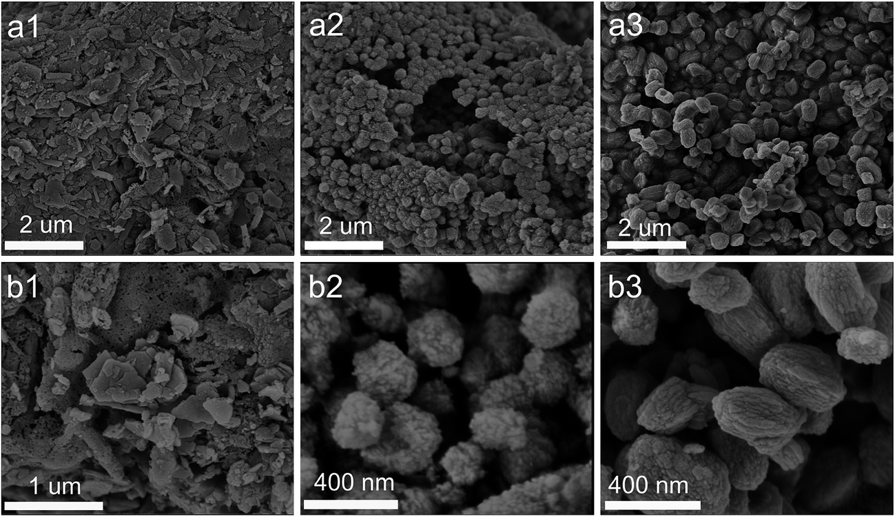 | ||
| Fig. 1 SEM images of LMK (a1 and b1), ZSM-11-K (a2 and b2) and ZSM-11-C (a3 and b3). | ||
The XRD patterns in Fig. 2a show that LMK was X-ray amorphous. Moreover, a spot of crystalline quartz was observed corresponding to its characteristic peaks at 2θ of 26.6° and 20.8°. By contrast, ZSM-11-C and ZSM-11-K displayed the characteristic peaks of ZSM-11 zeolites (JCPDS card no. 38-246, 55-349). The enlarged XRD patterns at 2θ of 20–27° and 43–47° are illustrated in Fig. 2b and c. Compared to standard ZSM-5 (JCPDS card no. 00-037-0361), the (421), (133) and (0,10,0) peaks belonging to ZSM-5 were not observed for ZSM-11-C and ZSM-11-K. This suggested that as-synthesized ZSM-11 zeolites were pure-phase and were free from ZSM-5 intergrowths.21,22 Furthermore, ZSM-11-K showed slightly lower crystallinity and broadening diffraction peaks at 2θ = 23–25° as compared to ZSM-11-C, which could be attributed to the smaller relative particle size of ZSM-11-K.
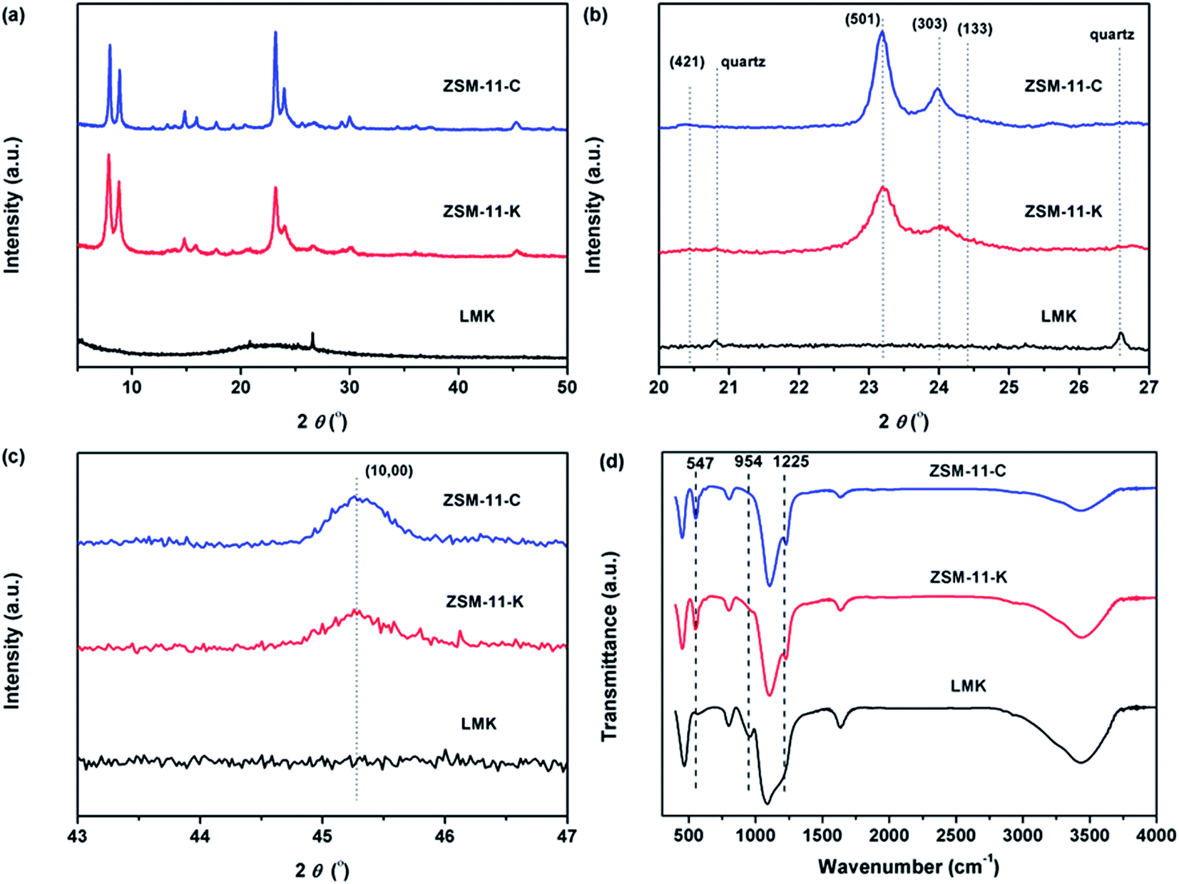 | ||
| Fig. 2 (a) XRD pattern, (b) enlarged 2θ region from 20° to 27°, (c) enlarged 2θ region from 43° to 47°, and (d) FTIR spectra of LMK, ZSM-11-C and ZSM-11-K. | ||
Fig. 2d displays the FT-IR spectra of samples LMK, ZSM-11-K and ZSM-11-C. In the FT-IR spectrum of LMK, the band at 954 cm−1 was ascribed to the Si–O stretching vibration in surface silanol groups.23 However, in the FT-IR spectrum of ZSM-11-K, this band vanished and new bands at 547 and 1225 cm−1 appeared, suggesting the formation of double five-membered rings characteristic of the pentasil family of zeolites.24 Moreover, both ZSM-11-K and ZSM-11-C exhibited characteristic bands at 449, 547, 800, 1099, and 1225 cm−1, indicating that ZSM-11 zeolites with high crystallinity were indeed obtained.25
As shown in Fig. 3, ZSM-11-C exhibited a type I isotherm, corresponding to the typical microporous structure. The N2 adsorption isotherms of ZSM-11-K (Fig. 3) represent a hybrid type I and IV with H3 hysteresis loops, indicating the presence of slit-shaped mesopores,26,27 which could be ascribed to the aggregation of nanocrystals. Furthermore, the mesopore-size-distributions calculated from the adsorption branch of N2 isotherms with the Barrett–Joyner–Halenda (BJH) model18 are also shown in Fig. 3 (insets). The mesopore-size-distribution for ZSM-11-K was inferred from the adsorption branch of the isotherm, to avoid the tensile-strength-effect.28 From the mesopore-size-distribution data, it was clear that the majority of mesopores were larger than 3 nm, albeit with a rather broad distribution due to the packing of primary crystallites that formed the agglomerated morphology (Fig. 1b2 and S2†). These results indicated that ZSM-11-K possibly had a hierarchical porosity: the slit-shaped intercrystalline mesopores that were produced from the aggregation of brick-type nanocrystals and the micropores intrinsically possessed by these brick-type nanocrystals. Moreover, ZSM-11-K exhibited larger BET surface areas (SBET) than did ZSM-11-C, which matched well with the relatively small particle size of ZSM-11-K (Table 1).
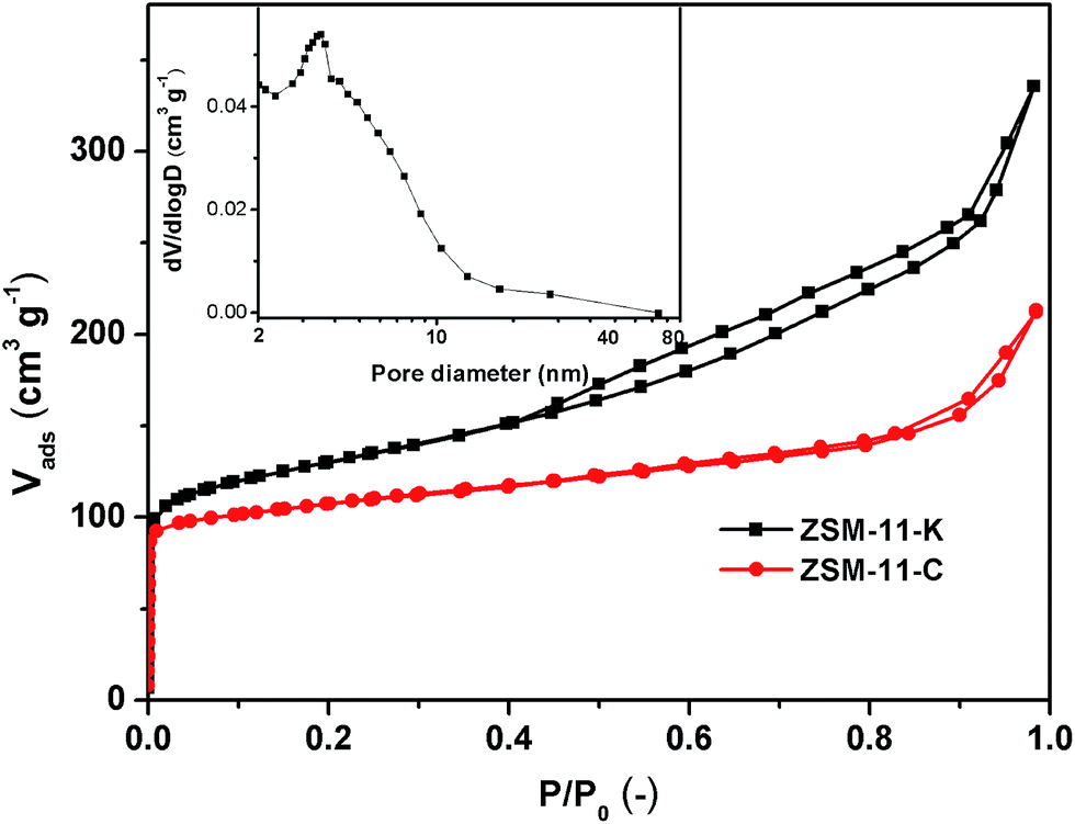 | ||
| Fig. 3 N2 isotherms and BJH pore size distributions of ZSM-11-C and ZSM-11-K. | ||
| Sample | Si/Ala | SBETb (m2 g−1) | Smesoc (m2 g−1) | Vtotald (cm3 g−1) | Vmicroc (cm3 g−1) | Vmesoe (cm3 g−1) |
|---|---|---|---|---|---|---|
| a Determined by XRF with a Shimadzu Model XRF-1800 instrument.b BET method.c t-Plot method.d Volume adsorbed at p/p0 = 0.99.e Vmeso = Vtotal − Vmicro. | ||||||
| ZSM-11-C | 29 | 320 | 128 | 0.19 | 0.12 | 0.07 |
| ZSM-11-K | 27 | 428 | 228 | 0.41 | 0.11 | 0.30 |
The strength and concentration of the acidity of ZSM-11-C and ZSM-11-K were determined by NH3-TPD, as shown in Fig. 4a and Table 2. Two desorption peaks were evident at about 200 °C and 400 °C, which were associated with ammonia physically adsorbed onto weak acid sites (WAS) and chemisorbed onto strong acid sites (SAS), respectively.29 From Fig. 4a and Table 2, it was confirmed that ZSM-11-K exhibited fewer SAS and more WAS than did ZSM-11-C. Notably, ZSM-11-K possessed a lower concentration of total acid sites than did ZSM-11-C, even though they shared close Si/Al ratios (Table 1). This should be attributed to the inability of some Al species in LMK to be incorporated into the ZSM-11 framework.30
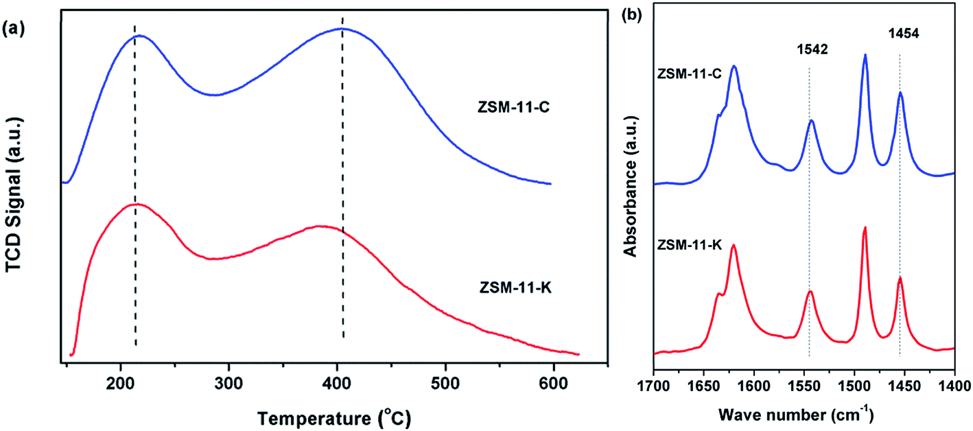 | ||
| Fig. 4 (a) NH3-TPD profiles and (b) Py-IR profiles of ZSM-11-C and ZSM-11-K. | ||
| Sample | Acidity by strengtha (mmol g−1) | Acidity by typeb (mmol g−1) | ||||
|---|---|---|---|---|---|---|
| SAS | WAS | Total | LAS | BAS | Total | |
| a The concentration of strong acid sites (CSAS) and weak acid sites (CWAS) determined by NH3-TPD.b The concentration of Lewis acid sites (CLAS) and Brønsted acid sites (CBAS) calculated by Py-IR after evacuation at 350 °C. | ||||||
| ZSM-11-C | 0.686 | 0.518 | 1.204 | 0.256 | 0.220 | 0.476 |
| ZSM-11-K | 0.569 | 0.590 | 1.159 | 0.215 | 0.224 | 0.439 |
Py-IR was employed to analyze the Lewis acid sites (LAS) and Brønsted acid sites (BAS) of the catalysts. As demonstrated in Fig. 4b, the IR bands detected at 1454 and 1542 cm−1 were attributed to coordinate interaction of bound pyridine with LAS and to pyridinium ions generated on BAS, respectively.31 Moreover, the concentrations of LAS (CLAS) and BAS (CBAS) were calculated according to the integrated area of the IR bands at about 1454 and 1542 cm−1, as shown in Table 2. It was found that the CBAS was similar for ZSM-11-K and ZSM-11-C, whereas the CLAS of ZSM-11-C was obviously higher than that of ZSM-11-K. Additionally, ZSM-11-K had a lower concentration of total acid sites than did ZSM-11-C, which was consistent with the results of NH3-TPD.
To obtain a comprehensive idea of the intrinsic acidic properties of ZSM-11-K and ZSM-11-C, the acidity obtained by NH3-TPD and Py-IR was also normalized by surface areas (Table S3†). It has been proposed that the BAS is mainly located in micropores.32,33 Hence the BAS was normalized by micropore surface areas. Notably, it was hard to probe the exact location of LAS, WAS and SAS. Thus, the LAS, WAS and SAS were roughly normalized by SBET. ZSM-11-K showed obviously lower concentrations of LAS, WAS and SAS than did ZSM-11-C, due to its large SBET. Furthermore, it was found that the two samples exhibited similar CBAS, which was consistent with the results obtained from the acidity normalized by mass.
To explore the potential of the as-synthesized zeolites as catalysts, we compared the catalytic performance of ZSM-11-K and ZSM-11-C in the MTA reaction. As shown in Fig. 5a, ZSM-11-K and ZSM-11-C displayed high methanol conversion (above 98%) within about 180 h. After that, ZSM-11-C deactivated rapidly, while ZSM-11-K maintained methanol conversion above 98% until 236 h. This indicated that ZSM-11-K exhibited better catalyst stability than did ZSM-11-C. Previously, it has been reported that the hierarchical nanocrystalline ZSM-5 zeolites showed high catalyst stability, due to the improved diffusion.2,34 With time-on-stream (TOS) increasing, the aromatic selectivity of the two catalysts decreased monotonously. However, ZSM-11-K displayed higher aromatic selectivity than ZSM-11-C (Fig. 5a and b). Notably, it was well accepted that aromatization activity could be enhanced by increasing the CBAS and improving diffusion properties.2,35,36 The results showed that the two catalysts exhibited similar CBAS (Table 2 and S3†), while ZSM-11-K had more mesopores and smaller crystallite size than ZSM-11-C. As small crystallite size (Thiele theorem) and the presence of auxiliary porosity enhanced diffusion properties, that was also a determinant of the catalyst lifetime in the MTA reaction.1,2 Therefore, the high aromatic selectivity for ZSM-11-K should be attributed to the high mesopore volume (Table 1) and small crystallite size (Fig. 1b2 and S2†). In summary, these reactivity results suggest that ZSM-11-K is more promising for catalytic applications than ZSM-11-C.
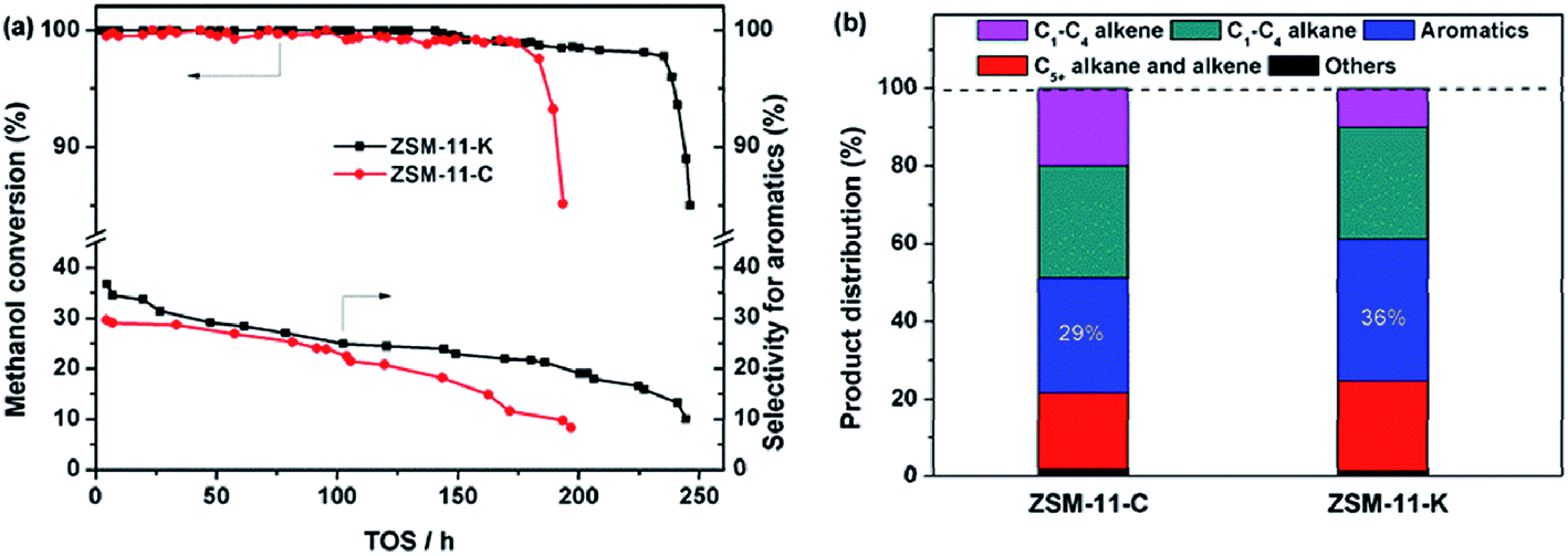 | ||
| Fig. 5 (a) Methanol conversion and the selectivity for aromatics as a function of time-on-stream (TOS) and (b) initial product distribution obtained at 2 h of TOS (the reaction became stable). | ||
Technically, industrial catalysts are rarely permitted to run until complete loss of activity; thus the total conversion capacities were supplemented to qualitatively evaluate the catalytic performance of ZSM-11-K and ZSM-11-C. As explained by Bjørgen et al.,37 this was done by plotting the methanol conversion versus the grams of methanol converted per gram of catalyst, and extrapolating the curves towards zero conversion, thereby obtaining the value for the total capacity of the catalyst for the methanol to hydrocarbons reaction (MTH) until complete deactivation; this is illustrated in Fig. 6. For ZSM-11-C, a total conversion capacity of 428 g (methanol) (g (catalyst))−1 was observed, and for ZSM-11-K it was 539 g g−1. These calculated values suggested that the catalyst utilization of ZSM-11-K was obviously higher than that of ZSM-11-C.
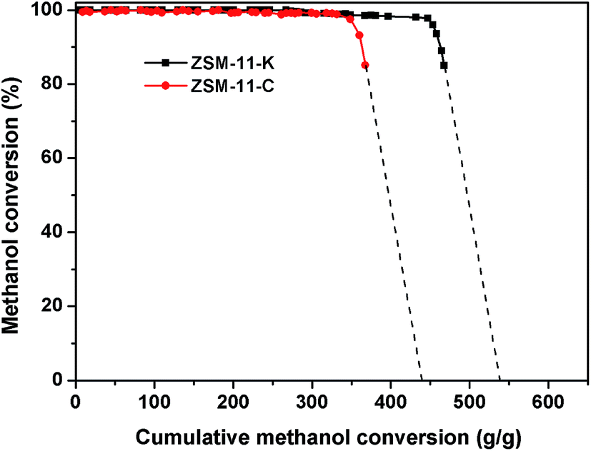 | ||
| Fig. 6 Methanol conversion versus the cumulative amount of methanol converted to hydrocarbon. Extrapolation of the curves towards zero conversion gives the total conversion capacities of the two catalysts. | ||
The unsaturated species, including alkenes, aromatics and cyclic alkenes, were transformed into coke through dehydrogenation and condensation. Coke was trapped inside the cavity and deposited on the external surface of the catalysts, which resulted in catalyst deactivation.38 The TG was used to estimate the content and rate of coke deposited on the catalysts. Fig. 7 shows that ZSM-11-K had a higher coke content than ZSM-11-C, which can be attributed to the abundance of mesopores in ZSM-11-K. This was also reported for other coked hierarchical catalysts.39–41 The mesopores could enhance the capacity of accommodating the coke of the catalysts and thus result in high catalyst utilization.39 Furthermore, the coking rate, defined as the coke production per hour, was calculated. It was about 2.37 mg g−1 h−1 for ZSM-11-C and 2.20 mg g−1 h−1 for ZSM-11-K. The lower coking rate of ZSM-11-K was ascribed to the lower CLAS. Guisnet et al. proposed the role of acid sites in the formation of coke: (i) the higher concentration of acid sites favors the condensation reactions, resulting in a faster coking rate; (ii) the stronger acid sites could speed up these reactions and therefore result in a faster coking rate.38 These results suggest that it was reasonable for ZSM-11-K to exhibit outstanding catalyst stability, owing to its better capacity of accommodating the coke and the lower coking rate.
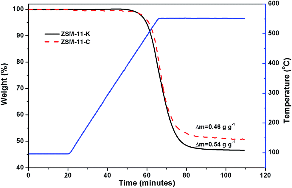 | ||
| Fig. 7 TG profiles of the used catalysts. | ||
4. Conclusions
In summary, we have successfully prepared pure-phase hierarchical aggregates of nano ZSM-11 (240 nm) using natural kaolin as the alumina and silica source with the aid of TBPOH via steam-assisted crystallization. The hierarchical ZSM-11 exhibited good aromatization activity and superior catalyst stability in the MTA reaction. Moreover, this study suggested a new protocol to control the topology and hierarchical architecture of ZSM-11, while at the same time using a low-cost starting material. Further studies on the crystallization mechanism of the hierarchical aggregates of nano ZSM-11 will be pursued in future work.Acknowledgements
We gratefully acknowledge funding from the Doctoral Fund of Ministry of Education (20130074110018) and the National Natural Science Foundation of China (21446003).References
- K. Shen, N. Wang, W. Z. Qian, Y. Cui and F. Wei, Catal. Sci. Technol., 2014, 4, 3840–3844 CAS.
- Y. Gao, G. Wu, F. W. Ma, C. T. Liu, F. Jiang, Y. Wang and A. J. Wang, Microporous Mesoporous Mater., 2016, 226, 251–259 CrossRef CAS.
- K. Shen, W. Z. Qian, N. Wang, J. Zhang and F. Wei, J. Mater. Chem. A, 2013, 1, 3272–3275 CAS.
- F. Bleken, W. Skistad, K. Barbera, M. Kustova, S. Bordiga and P. Beato, et al., Phys. Chem. Chem. Phys., 2011, 13, 2539–2549 RSC.
- H. Liu, S. J. Xie, W. Xin, S. Liu and L. Y. Xu, Catal. Sci. Technol., 2016, 6, 1328–1342 CAS.
- M. Y. Kustova, P. Hasselriis and C. H. Christensen, Catal. Lett., 2004, 96, 205–211 CrossRef CAS.
- H. B. Zhu, Z. Liu, D. Kong, Y. Wang and Z. K. Xie, J. Phys. Chem. C, 2008, 112, 17257–17264 CAS.
- H. Youssef, D. Ibrahim and S. Komarneni, Microporous Mesoporous Mater., 2008, 115, 527–534 CrossRef CAS.
- T. Li, H. Y. Liu, Y. Fan, P. Yuan, G. Shi, X. T. Bi and X. J. Bao, Green Chem., 2012, 14, 3255–3259 RSC.
- S. Chandrasekhar and P. N. Pramada, J. Porous Mater., 1999, 6, 283–297 CrossRef CAS.
- J. Zhu, Y. Cui, Y. Wang and F. Wei, Chem. Commun., 2009, 3282–3284 RSC.
- M. L. Mignoni, D. I. Petkowicz, N. R. C. Fernandes Machado and S. B. C. Pergher, Appl. Clay Sci., 2008, 41, 99–104 CrossRef CAS.
- A. S. Kovo, O. Hernandez and S. M. Holmes, J. Mater. Chem., 2009, 19, 6207–6212 RSC.
- K. K. Zhu, J. Sun, J. Liu, L. Wang, H. Wan and J. Hu, et al., ACS Catal., 2011, 1, 682–690 CrossRef CAS.
- X. Y. Zhang, D. Liu, D. Xu, S. Asahina, K. A. Cychosz, K. V. Agrawal, Y. A. Wahediet, A. Bhan, S. A. Hashimi, O. Terasaki, M. Thommes and M. Tsapatsis, Science, 2012, 336, 1684–1687 CrossRef CAS PubMed.
- W. Song, Z. Liu, L. Liu, A. L. Skov, N. Song, G. Xiong, K. K. Zhu and X. G. Zhou, RSC Adv., 2015, 5, 31195–31204 RSC.
- S. Brunauer, P. H. Emmett and E. Teller, J. Am. Chem. Soc., 1938, 60, 309–319 CrossRef CAS.
- L. G. Joyner, E. P. Barrett and R. Skold, J. Am. Chem. Soc., 1951, 73, 3155–3158 CrossRef CAS.
- B. C. Lippens and J. H. de Boer, J. Catal., 1965, 4, 319–323 CrossRef CAS.
- C. D. Madhusoodana, R. N. Das, Y. Kameshima and K. Okada, J. Porous Mater., 2005, 12, 273–280 CrossRef CAS.
- G. A. Jablonski, L. B. Sand and J. A. Gard, Zeolites, 1986, 6, 396–402 CrossRef CAS.
- M. Conte, B. Xu, T. E. Davies, J. K. Bartley, A. F. Carley, S. H. Taylor, K. Khalidet and G. J. Hutchings, Microporous Mesoporous Mater., 2012, 164, 207–213 CrossRef CAS.
- M. A. Camblor, A. Corma and J. Perez-Pariente, J. Chem. Soc., Chem. Commun., 1993, 6, 557–559 RSC.
- J. C. Jansen, F. J. van der Gaag and H. van Bekkum, Zeolites, 1984, 4, 369–372 CrossRef CAS.
- S. Mintova, N. Petkov, K. Karaghiosoff and T. Bein, Microporous Mesoporous Mater., 2001, 50, 121–128 CrossRef CAS.
- Y. Tao, H. Kanoh, L. Abrams and K. Kaneko, Chem. Rev., 2006, 106, 896–910 CrossRef CAS PubMed.
- J. C. Kim, R. Ryoo, M. V. Opanasenko, M. V. Shamzhy and J. Čejka, ACS Catal., 2015, 5, 2596–2604 CrossRef CAS.
- J. C. Groen, J. C. Jansen, J. A. Moulijn and J. Pérez-Ramírez, J. Phys. Chem. B, 2004, 108, 13062–13065 CrossRef CAS.
- M. Niwa and N. Katada, Catal. Surv. Asia, 1997, 1, 215–226 CrossRef CAS.
- F. Pan, X. Lu, Q. Zhu, Z. Zhang, Y. Yan, T. Wang and S. Chen, J. Mater. Chem. A, 2015, 3, 4058–4066 CAS.
- N. Topsoe, F. Joensen and E. Derouane, J. Catal., 1988, 110, 404–406 CrossRef CAS.
- T. Armaroli, M. Bevilacqua, M. Trombetta, F. Milella, A. D. G. Alejandre, J. Ramírez, B. Notari, R. J. Willey and G. Busca, Appl. Catal., A, 2001, 216, 59–71 CrossRef CAS.
- K. Barbera, F. Bonino, S. Bordiga, T. V. W. Janssens and P. Beato, J. Catal., 2011, 280, 196–205 CrossRef CAS.
- K. Shen, W. Qian, N. Wang, C. Su and F. Wei, J. Mater. Chem. A, 2014, 2, 19797–19808 CAS.
- Y. Gao, B. Zheng, G. Wu, F. Ma and C. Liu, RSC Adv., 2016, 6, 83581–83588 RSC.
- V. R. Choudhary and A. K. Kinage, Zeolites, 1995, 15, 732–738 CrossRef CAS.
- M. Bjørgen, F. Joensen, M. Spangsberg Holm, U. Olsbye, K. P. Lillerud and S. Svelle, Appl. Catal., A, 2008, 345, 43–50 CrossRef.
- M. Guisnet, L. Costa and F. R. Ribeiro, J. Mol. Catal. A: Chem., 2009, 305, 69–83 CrossRef CAS.
- F. Schmidt, C. Hoffmann, F. Giordanino, S. Bordiga, P. Simon, W. Carrillo-Cabrera and S. Kaskel, J. Catal., 2013, 307, 238–245 CrossRef CAS.
- C. G. Yang, M. H. Qiu, S. W. Hu, X. Q. Chen, G. F. Zeng, Z. Y. Liu and Y. H. Sun, Microporous Mesoporous Mater., 2016, 231, 110–116 CrossRef CAS.
- J. Kim, M. Choi and R. Ryoo, J. Catal., 2010, 269, 219–228 CrossRef CAS.
Footnote |
| † Electronic supplementary information (ESI) available. See DOI: 10.1039/c7ra03141f |
| This journal is © The Royal Society of Chemistry 2017 |