 Open Access Article
Creative Commons Attribution 3.0 Unported Licence
Assembly of CdS nanoparticles on boron and fluoride co-doped TiO2 nanofilm for solar energy conversion applications†
Qi Lua,
Ling Li*a,
Junying Xiaoa,
Huidong Suia,
Jianwei Lia,
Ruyue Duana,
Jingbo Lia,
Wenming Zhang *a,
Xiaowei Lia,
Kunyanga,
Yucang Zhang*b and
Mingxing Wu*ac
aHebei Key Lab of Optic-electronic Information and Materials, College of Physics Science and Technology, Hebei University, Baoding 071002, P. R. China. E-mail: lilinghbu@163.com; wmzhang@hbu.edu.cn; Fax: +86 312 5079355; Tel: +86 312 5079355
bKey Laboratory of Ministry of Education for Advanced Materials in Tropical Island Resources in Hainan University, Haikou 570228, P. R. China. E-mail: yczhang@hainu.edu.cn
cCollege of Chemistry and Material Science, Hebei Normal University, No. 20 Rd. East of 2nd Ring South, Yuhua District, Shijiazhuang City, Hebei Province 050024, P. R. China. E-mail: mingxing.wu@mail.hebtu.edu.cn
First published on 2nd June 2017
Abstract
A highly crystalline mesoporous boron and fluoride (B/F) co-doped TiO2 nanomaterial is successfully synthetized using a facile process, followed by chemical bath deposition (CBD) in an organic solution to prepare the QD-cell to ensure high wettability and superior penetration ability of the B/F co-doped TiO2 films. A modified polysulfide redox couple, ((CH3)4N)2S/((CH3)4N)2Sn, was employed in a cadmium sulfide (CdS) quantum dot (QD)-sensitized B/F co-doped TiO2 solar cell covered with ZnS passivation layers with cobalt sulfide (CoS) as a counter electrode; then, an open-circuit photovoltage of 1.223 V, a high FF of 85.9%, a short-circuit photocurrent (Jsc) of 4.52 mA cm−2, and a high overall energy conversion of 4.74% were obtained.
1. Introduction
Quantum-dot-sensitized solar cells (QDSSCs), as a derivative of dye-sensitized solar cells (DSCs), have attracted extensive attention in recent years due to their higher theoretical conversion efficiency and lower production costs. Recently, a series of QDs (CdS, CdSe, PbS, CdSexTe1−x, and CuInS2) and their derivatives1–10 were employed as light-absorber sensitizers. The metal-oxide film electrode, electrolyte as well as counter electrode were also systematically optimized to improve the performance of QDSCs11–16 as inorganic QDs exhibit various advantages over organic dyes, such as easy obtainability, low cost, high molar extinction coefficiency and convertibility of the band gap.17–19 More importantly, QDs can harvest hot electrons, generate multiple electron–hole pairs and be designed with intermediate bands, which offer the opportunity to achieve considerable high performance solar cells.20 The theoretical conversion efficiency of QDSSCs is as high as 44%,21,22 which makes the QDs prominent candidates for application in solar cells. However, the photoelectric conversion efficiency of QDSSCs is still lower than that of the DSSCs because of the severe recombination of electrons of the quantum dot conduction band. Recent advances in quantum dot solar cells (QDSCs) have propelled them to the forefront of the photovoltaic research, for power conversion efficiencies (PCEs) in excess of 11% that have been achieved by Zhong's group.23 This is a new record efficiency for QD solar cells in any configuration and also a new record for QDSSCs with any QD sensitizer. To date, the highest reported efficiency of CdS (QDSSCs) using I−/I3− based electrolyte and Pt counter electrode is 1.84%.24In the past few years, there has been a considerable effort to enhance the energy conversion efficiencies of QDSSCs using various strategies. A review of the literature indicates that much of the research in QDSSCs has been focused on the synthesis of various structures of photoanodes,25,26 sensitizing the photoanodes with various combinations of QDs,27,28 depositing QDs on an anode with various chemical methods,29 and changing the chemical composition of the redox electrolyte.30–34 With an important role in QDSSCs, TiO2 films act as the support for QD loading and charge transport medium, and thus numerous studies have been carried out to exploit efficient TiO2 nanostructures.35–37 Chen et al. fabricated a novel double-sided CdS quantum-dot-sensitized TiO2 nanotube (TNT)/ITO photoelectrode, and the experimental results show that the double-sided CdS quantum-dot-sensitized NT/ITO photoelectrodes show enhanced light absorption and achieve an optimum conversion efficiency of 7.5%, which is an enhancement of about 120% when compared with the single-sided CdS/TNT/Ti photoelectrode.38 In either DSCs or QDSSCs, the nanoparticle porous film electrode plays a key role in the improvement of power conversion efficiency. However, TiO2 is a large band gap semiconductor (Eg = 3.2 eV), which can only be excited by UV radiation at a wavelength below 390 nm. To make better use of the full light spectrum, doping TiO2 with metal and nonmetal elements has been considered as a promising way to tailor the electronic properties of TiO2 photoanodes in QDSSCs and has succeeded in improving photovoltaic performance of QDSSCs. In particular, non-metallic doping of TiO2 electrodes has attracted much attention due to the excellent performance of the resulting doped material. Moreover, the technology of co-doping has been proven to be an effective solution to improve the performance of the TiO2 electrodes due to its charge compensation on the basis of different ions through an internal charge transfer, with a large stabilization effect resulting in a less defective co-doped TiO2 system.39,40
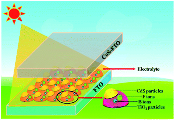
To the best of our knowledge, research into non-metallic B/F co-doping in QDSSCs has not been systematically carried out. Therefore, it would be highly desirable to research the co-doping effect on QDSSC systems. Herein, we investigated the effect of B/F co-doping on the QDSSC's performance and demonstrated that the application of a B/F co-doped TiO2 electrode in QDSSCs can enhance the photovoltaic performance of QDSSCs. In this study, we report the first example of CdS quantum dot (QD)-sensitized B/F co-doped TiO2 solar cells with ZnS passivation layers using CoS as a counter electrode. The configuration of the cells is illustrated in Scheme 1. As a result, a CdS QD-sensitized B/F co-doped TiO2 solar cell using the same ((CH3)4N)2S/((CH3)4N)2Sn electrolyte shows a promising photovoltaic performance, with an efficiency of 4.74%, a significantly high Voc of 1.223 V, and a high FF of 85.9% with a short-circuit photocurrent (Jsc) of 4.52 mA cm−2.
2. Experimental
2.1 Preparation of B–F co-doped TiO2 nanoparticles
The doped and modified nanocrystalline powder was synthesized using the sol–gel route, followed by pyrolysis and calcination treatments. Titanium tetraisopropoxide (Ti(Oi-Pr)4) (Alfa Aesar), acetylacetone (acac, Aldrich), boron fluoride acetic acid complex (BF3·2CH3CO2, 97%), and tetrafluoroboric acid (HBF4, 48%, Strem Chemicals, Newburyport, MA) were used as received. An alcoholic complex was prepared by slowly adding BF3·2CH3CO2 (0.03 mol) to 10 mL of EtOH at 0 °C under ambient conditions, which formed a homogeneous and viscous solution. Once this solution cooled to room temperature, it was slowly added to Ti(OiPr)4 (0.07 mol) in 10 mL iPrOH, producing a vivid yellow homogeneous solution. After the mixture was stirred for 15 min, deionized water (500 mL) was added, which brought no discernible change; hence 100 mL of HBF4 was added, and after a few minutes, the yellow solution became turbid. It was then refluxed at 80 °C for 30 min, which effectively rehomogenized the mixture (pH: 1–2). After the mixture was refluxed for 6 h at 70 °C, Ti(OiPr)4 (0.069 mol) was added to the reaction vessel to facilitate particle formation, and refluxing was continued for 18 h at 70–80 °C while stirring. The volume of the solution was reduced to approximately one-fifth, yielding a finely dispersed white powder. The powder was separated by filtration through a medium porosity ceramic frit, repeatedly washed with water until the pH of the filtrate was neutral and finally dried at 100 °C in an oven.The as-synthesized material was subjected to different thermal treatments. Specifically, the purified powder was placed in a borosilicate test tube, which was attached to a glass manifold employing Cajon connectors and stainless steel tubing, and was heated to 400 °C (4 °C min−1). A short ceramic oven was employed to allow manipulation of the sample tube while it was still connected to the manifold. The sample's appearance was monitored visually over the course of the heating procedure, and the temperature was increased to 500 °C while under vacuum or under gas flow for periods of up to 3 h. The heavily reduced powder, on the basis of its coloration (gray), was exposed briefly to air by opening the vessel to the atmosphere or to pure oxygen gas that was delivered directly to the sample container. The final stage of the thermal treatment consisted of the evacuation of the tube's contents or rapidly cooling it to 100 °C while in air.
2.2 Deposition of CdS QD-sensitized B–F co-doped TiO2 solar cells
The B–F co-doped TiO2 (B–F–TiO2) oxide used in the front sub-cell electrode was individually mixed with a polymer binder, and dissolved in terpineol, resulting in a paste. The paste was then coated on the fluorine-doped (FTO) SnO2 conductive glass (TEC15, 15 Ω per square, Pilkington, USA) by screen printing and then dried for 5 min at 125 °C. This procedure was repeated 4 times (to give ca. 8 μm film). The electrodes were gradually heated at 500 °C for 30 min, and the sintered film was further treated with 40 mM TiCl4 aqueous solution at 70 °C for 30 min, washed with ethanol and water, and annealed at 480 °C for 30 min. SILAR was used to assemble CdS-QDs into the B–F–TiO2 photoelectrode. B–F–TiO2 films were surface-modified by immersing in 0.1 M mercaptoacetic acid (TGA) for 1 min; the TGA-modified B–F–TiO2 substrate electrode was dipped first into an ethanol solution containing Cd(NO3)2 (0.5 M) for 1 min, rinsed with ethanol, and dried with an air gun. The electrodes were then dipped for another 1 min into a Na2S methanol solution (0.5 M) and rinsed again with methanol. The process was repeated up to N cycles (N = 1 to 5). These as-prepared electrodes are represented herein as “B–F–TiO2/TGA/CdS-N” electrodes.41 The CdS-sensitized B–F–TiO2 films were coated with ZnS for 3 cycles by dipping alternately into 0.1 M Zn(OAc)2 methanol solution and 0.1 M Na2S solutions for 1 min per dip. As the working electrode, CoS was separated with a hot-melt Surlyn 1702 film (25 μm, DuPont). Cleaned FTO glass was dipped into 0.5 M Co(NO3)2 ethanolic solution for 30 s, rinsed with ethanol, and dried with an air gun. The sample was then dipped for 30 s into 0.5 M Na2S methanolic solution, followed by rinsing with methanol and drying with an air gun. The process was repeated for up to five cycles to obtain the CoS electrode.42 The electrolyte solution consisting of 0.01 M tetramethyl ammonium sulfide ((CH3)4N)2S, 0.002 M S, 0.02 M LiClO4, 0.02 M 4-tert-butylpyridine (TBP), 3-methoxypropionitrile (MPN) was used as a solvent for the polysulfide electrolyte. The ((CH3)4N)2S was prepared by heating tetramethyl ammonium hydroxide ((CH3)4N)OH and ammonium sulfide (NH4)2S at 100 °C.43 We investigated three experiment samples with the same conditions five times to test the repeatability and stability of the experiment, which gave excellent results.3. Optical and photovoltaic measurements
Crystal structures of the samples were analyzed by X-ray diffraction (XRD) (Japan, XD-3A) using Cu Kα radiation and a scintillation counter detector. The patterns were recorded in the 2θ range of 20–80°. The elemental distribution and concentration were analyzed by an energy dispersive spectrometer (EDS) (Oxford Inca) attached to the field emission scanning electron microscope (FESEM). UV-vis absorption spectra were recorded on a UV-visible spectrometer (U-4100, HITACHI, Japan). The electronic structure and B–F-doping amount was determined by X-ray photoelectron spectroscopy (XPS) (AXIS-165 Shimadzu, Japan). Transmission electron microscopy (TEM) images were obtained using a JEOL JEM-2100 instrument. The flat-band potential (Vfb) of the nanostructured TiO2 and B–F–TiO2 electrode was determined by measuring the absorbance at 780 nm as a function of the applied potential. For the spectroscopic electrochemistry measurement, an 8 μm thick TiO2 film formed the working electrode (1 cm2 surface area) of a three-electrode photoelectrochemical cell employing a platinum wire counter electrode and an Ag/AgCl reference electrode. Potential control was carried out on a CHI 660E potentiostat, and the applied potential was scanned at 5 mV s−1. A 780 nm monochromatic light source was obtained from the UV-vis spectrophotometer (U-4100, HITACHI, Japan). For each determination of Vfb, a new working electrode and freshly prepared electrolyte solution were used.44The irradiation source for the photocurrent density–voltage (J–V) measurement was an AM 1.5G solar simulator (16S-002, SolarLight Co. Ltd., USA). The incident light intensity was 100 mW cm−2, calibrated with a standard Si solar cell. The novel solar cells were masked to a working area of 0.159 cm2. The J–V curves were obtained using a linear sweep voltammetry (LSV) method on an electrochemical workstation (LK9805, Lanlike Co. Ltd., China). The measurement of the incident photon-to-current conversion efficiency (IPCE) was performed using a Hypermonolight (SM-25, Jasco Co. Ltd., Japan) system. The short current density was calibrated by integrating the product of the IPCE value and solar photon density against the wavelength.45 Electrochemical impedance spectroscopy (EIS) for QDSSCs under dark, with a bias of −0.75 V, was measured using an impedance/gain-phase analyzer (ZENIUM, ZAHNER, Germany). The spectral regions were scanned using a frequency range of 10−1 to 105 Hz at room temperature. The alternate current (AC) amplitude was set at 10 mV.
4. Results and discussion
4.1 Optical properties
Fig. 1 shows that the absorbance intensity of these films increases with noticeable shifts of the absorbance edge towards longer wavelength, and a shoulder to the visible light region was observed with doped B and F, where the film doped with B and F shows yellow colour while the undoped film shows white colour. The UV-vis absorption spectra of the B–F-doped TiO2/TGA/CdS-3 film and the TiO2/TGA/CdS-3 film in the ((CH3)4N)2S/((CH3)4N)2Sn electrolyte also shifted about 30 nm to longer wavelength, which is beneficial for for the B–F-doped TiO2/TGA/CdS-3 film to capture more light and to obtain higher light to electrical efficiency.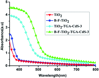 | ||
| Fig. 1 UV-vis absorption spectra of the bare TiO2 film, B–F doped TiO2 film, TiO2/TGA/CdS-3 film, and B–F-doped TiO2/TGA/CdS-3 film. | ||
4.2 Spectro-electrochemical properties
In order to further investigate the cause of the enhancement of Voc in QDSSCs, the spectro-electrochemical measurements for undoped and B/F co-doped TiO2 were carried out, and the results are shown in Fig. 2. The flat-band potential Vfb of TiO2 samples with and without B/F co-doping were determined as −2.2 V and −2.097 V (vs. Ag/AgCl), respectively. Therefore, a higher quasi-Fermi level closer to the conduction band was definitely achieved, which could lead to the larger Voc for liquid-state QDSSCs employing a B/F co-doped TiO2 electrode.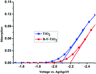 | ||
| Fig. 2 Absorbance measured at 780 nm as a function of applied potential for nanostructured undoped and B/F co-doped TiO2 electrodes at 298 K in 3 M KCl solution (Ag/AgCl reference electrode). | ||
Under Fermi level pinning, the two parameters (Voc and Vfb) are linked by eqn (1).46
| Voc = |Vfb − Vred| | (1) |
4.3 Device properties
New CdS-functionalized QDSSCs were fabricated in this study in which tetramethyl ammonium sulphide/polysulfide, ((CH3)4N)2S/((CH3)4N)2Sn, was used as the redox couple in an organic solvent (3-methoxy propionitrile (MPN)). The configuration of the cells is illustrated in Scheme 1.The fill factor (FF) and the overall light-to-electrical energy conversion efficiency (η) of the DSSC were calculated according to the following equations:47
 | (2) |
 | (3) |
The cell based on B–F–TiO2/TGA/CdS-3 photoelectrode was found to give the best performance in this series. Under one sun illumination (AM 1.5G, 100 mW cm−2), this cell shows an ideal energy conversion efficiency of 4.74%, a large open-circuit photovoltage of 1.223 V and an extremely high FF value up to 85.9% with a short-circuit photocurrent (Jsc) of 4.52 mA cm−2; see Fig. 3. Compared with the cell based on TiO2/TGA/CdS-3, the Jsc was improved from 3.54 mA cm−2 to 4.52 mA cm−2, leading to an improvement in efficiencies from 3.45% to 4.74%, and the Voc improved from 1.124 V to 1.223 V; the open-circuit potential of the B–F–TiO2 electrode is negatively shifted by 99 mV compared to the undoped TiO2 electrode, which is consistent with the flat-band potential result. Moreover, using Voc as a reference is a standard way to describe the J–V characteristics of an electrochemical cell. Voc is the light intensity dependent rest potential of the cell. Connecting the cell to an electric load causes the electric current to flow in the cell, which gives rise to voltage losses, Vk, that are also called overpotentials or overvoltages, due to the internal cell resistances Rk. This decreases the cell voltage from its open-circuit value and determines the shape of the solar cell J–V curve and hence its fill factor.48
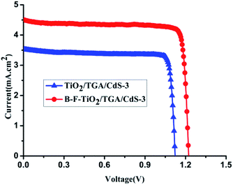 | ||
| Fig. 3 The J–V characteristics of the B–F–TiO2/TGA/CdS-3 cell and TiO2/TGA/CdS-3 cell measured under illumination of 100% sun (AM 1.5, 100 mW cm−2). | ||
The IPCE (incident photon-to-current conversion efficiency, also referred to as quantum efficiency) of the QDSSCs was determined by measuring the short-circuit current under incident monochromatic light irradiated through a monochromator with a grating of 1200 grooves per mm (Shimadzu Corporation, Kyoto, Japan); light from a xenon lamp passing through a monochromator (PXJ43B11-6W, Japan) was focused onto the cell. The IPCE is calculated according to the following equations:49,50
 | (4) |
As shown in Fig. 4, the incident photon-to-electron conversion efficiency spectrum of a B–F–TiO2/TGA/CdS-N based cell is about 80% in comparison with the TiO2/TGA/CdS-3 based cell, which is over 60% at 400 nm; therefore, the higher IPCE for the QDSC with the B–F–TiO2/TGA/CdS-N electrode than that with the TiO2/TGA/CdS-3 electrode is due to the B–F doping in the former, and the IPCE response in the visible region is in agreement with the trend for the Jsc. The active range in the visible light region is consistent with the corresponding UV-vis spectrum. The absorption edge of the B–F–TiO2/TGA/CdS-3-based cell shifts towards longer wavelength of about 30 nm compared to that of TiO2/TGA/CdS-3 based cell.
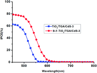 | ||
| Fig. 4 The incident photon-to-current conversion efficiency (IPCE) of the cell based on TiO2/TGA/CdS-3 electrode and B–F–TiO2/TGA/CdS-3 electrode. | ||
4.4 Electrochemical impedance spectra
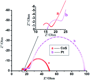
Fig. 5 shows the electrochemical impedance spectra51–54 for CoS and Pt counter electrodes with the same B–F–TiO2/TGA/CdS-3 film under forward bias (−0.75 V) in the dark. Using the identical electrolyte, the reduction rate is primarily determined by the catalytic activity of the counter electrodes. The cells for EIS measurements are symmetric thin-layer sandwich cells. At high frequency (>105 Hz), the ohmic series resistance (Rs) of the FTO layer, the CoS (or Pt) layer and the electrolyte can be determined in the middle frequency range of 10−1 to 105 Hz. In the low-frequency range of 0.1–10 Hz, the Warburg diffusion impedance, within the electrolyte, will be estimated. The Rs value being 3.325 Ohm for the CoS electrode is lower than the 7.583 Ohm for the Pt electrode.5. Conclusions
In summary, we have successfully developed the first example of an efficient CdS QD-sensitized B/F co-doped TiO2 solar cell with a modified polysulfide electrolyte in a pure organic system. B/F doping into the TiO2 lattice results in a red shift of the electronic absorption and enhanced photocurrent response. As a result, the performance of the cell is superb with an efficiency of 4.74%, a significantly high Voc of 1.223 V, and a high FF of 85.9% with a short-circuit photocurrent (Jsc) of 4.52 mA cm−2. The results show that the combination of B/F co-doped and CdS QD sensitization of the TiO2 thin films is an effective way to enhance the photoresponse, which is promising for photovoltaic and photoelectrochemical applications.Acknowledgements
We gratefully acknowledge the financial support from the following sources: the National Natural Science Foundation of China (NSFC) (Grants 21201053, 11104058, 51607054), the Fund in Hebei Province Natural Science (F2014201078, A2015201050), the Youth Fund in Hebei Province Department of Education China (QN2014057, ZD2016055, ZD2015044), the College students' innovative entrepreneurial training program in Hebei Province (201610075066, 2016105, 2016127, 2016170, 2016177), the Hebei university laboratory open project (sy201639), the Outstanding Youth Fund of Hebei University (2015JQ02), the Hebei province Outstanding Youth Fund (A2017201082), The Second Batch of Young Talent of Hebei Province, and the Graduate students' innovative supporting program in Hebei university (X201730)Notes and references
- W. T. Sun, Y. Yu, H. Y. Pan, X. F. Gao, Q. Chen and L. M. Peng, J. Am. Chem. Soc., 2008, 130, 1124–1125 CrossRef CAS PubMed.
- L. M. Peter, D. J. Riley, E. J. Tull and K. G. U. Wijayantha, Chem. Commun., 2002, 10, 1030–1031 RSC.
- Y. Tachibana, K. Umekita, Y. Otsuka and S. Kuwabata, J. Phys. D: Appl. Phys., 2008, 41, 102002 CrossRef.
- H. Zhang, K. Cheng, Y. M. Hou, Z. Fang, Z. X. Pan, W. J. Wu, J. L. Hua and X. H Zhong, Chem. Commun., 2012, 48, 11235–11237 RSC.
- H. C. Leventis, F. O'Mahony, J. Akhtar, M. Afzaal, P. O'Brien and S. A. Haque, J. Am. Chem. Soc., 2010, 132, 2743–2750 CrossRef CAS PubMed.
- A. Braga, S. Giménez, I. Concina, A. Vomiero and I. Mora-Seró, J. Phys. Chem. Lett., 2011, 2, 454–460 CrossRef CAS.
- Z. Pan, K. Zhao, J. Wang, H. Zhang, Y. Feng and X. Zhong, ACS Nano, 2013, 7, 5215–5222 CrossRef CAS PubMed.
- P. K. Santra, P. V. Nair, K. George Thomas and P. V. Kamat, J. Phys. Chem. Lett., 2013, 4, 722–729 CrossRef CAS PubMed.
- Z. Pan, I. Mora-Seró, Q. Shen, H. Zhang, Y. Li, K. Zhao, J. Wang, X. Zhong and J. Bisquert, J. Am. Chem. Soc., 2014, 136, 9203–9210 CrossRef CAS PubMed.
- T. L. Li, Y. L. Lee and H. Teng, Energy Environ. Sci., 2012, 5, 5315–5324 CAS.
- Z. Du, H. Zhang, H. Bao and X. Zhong, J. Mater. Chem. A, 2014, 2, 13033–13040 CAS.
- M. Hossain, J. Jennings, Z. Koh and Q. Wang, ACS Nano, 2011, 5, 3172–3181 CrossRef CAS PubMed.
- K. Zhao, H. Yu, H. Zhang and X. Zhong, J. Phys. Chem. C, 2014, 118, 5683–5690 CAS.
- J. Jin, X. Zhang and T. He, J. Phys. Chem. C, 2014, 118, 24877–24883 CAS.
- Y. Jiang, B. Yu, J. Liu, Z. Li, J. Sun, X. Zhong, J. Hu, W. Song and L. Wan, Nano Lett., 2015, 15, 3088–3095 CrossRef CAS PubMed.
- N. S. Makarov, H. McDaniel, N. Fuke, I. Robel and V. I. Klimov, J. Phys. Chem. Lett., 2014, 5, 111–118 CrossRef CAS PubMed.
- H. Chen, W. Y. Fu, H. B. Yang, P. Sun, Y. Y. Zhang, L. R. Wang, W. Y. Zhao, X. M. Zhou, H. Zhao, Q. A. Jing, X. F. Qi and Y. X. Li, Electrochim. Acta, 2010, 56, 919–924 CrossRef CAS.
- S. L. Cheng, W. Y. Fu, B. Y. Hai, L. N. Zhang, J. W. Ma, H. Zhao, M. L. Sun and L. H. Yang, J. Phys. Chem. C, 2011, 116, 2615–2621 Search PubMed.
- H. M. Chen, C. K. Chen, Y. C. Chang, C. W. Tsai, R. S. Liu, S. F. Hu, W. S. Chang and K. H. Chen, Angew. Chem., Int. Ed., 2010, 112, 6102–6105 CrossRef.
- J. J. Tian, Q. F. Zhang, L. L. Zhang, R. Gao, L. F. Shen, S. G. Zhang, X. H. Qu and G. Z. Cao, Nanoscale, 2013, 5, 936–943 RSC.
- Y. Qiu, S. Lu, S. Wang, X. Zhang, S. He and T. He, J. Power Sources, 2013, 253, 300–304 CrossRef.
- M. Deng, Q. Zhang, S. Huang, D. Li, Y. Luo, Q. Shen, T. Toyoda and Q. Meng, Nanoscale Res. Lett., 2010, 5, 986–990 CrossRef CAS PubMed.
- J. Du, Z. L. Du, J. S. Hu, Z. X. Pan, Q. Shen, J. K. Sun, D. H. Long, H. Dong, L. Sun, X. H. Zhong and L. J. Wan, J. Am. Chem. Soc., 2016, 138(12), 4201 CrossRef CAS PubMed.
- C. H. Chang and Y. L. Lee, Appl. Phys. Lett., 2007, 91, 053503 CrossRef.
- H. Wang, Y. S. Bai, H. Zhang, Z. H. Zhang, J. H. Li and L. Guo, J. Phys. Chem. C, 2010, 114, 16451–16455 CAS.
- Q. Zhang, X. Guo, X. Huang, S. Huang, D. Li, Y. Luo, Q. Shen, T. Toyoda and Q. Meng, Phys. Chem. Chem. Phys., 2011, 13, 4659–4667 RSC.
- Y. L. Lee and C. H. Chang, J. Power Sources, 2008, 185, 584–588 CrossRef CAS.
- L. W. Chong, H. T. Chien and Y. L. Lee, J. Power Sources, 2010, 195, 5109–5113 CrossRef CAS.
- V. Gonzalez-Pedro, C. Sima, G. Marzari, P. P. Boix, S. Gimenez, Q. Shen, T. Dittrich and I. Mora-Seró, Phys. Chem. Chem. Phys., 2013, 15, 13835–13842 RSC.
- H. Wang, T. Kubo, J. Nakazaki, T. Kinoshita and H. Segawa, J. Phys. Chem. Lett., 2013, 4, 2455–2460 CrossRef CAS.
- Y. Li, L. Wei, R. Zhang, Y. Chen, L. Mei and J. Jiao, Nanoscale Res. Lett., 2013, 8, 89–96 CrossRef PubMed.
- T. Shu, P. Xiang, Z. M. Zhou, H. Wang, G. H. Liu, H. W. Hanand and Y. D. Zhao, Electrochim. Acta, 2012, 68, 166–171 CrossRef CAS.
- J. T. Xi, Q. F. Zhang, K. Park, Y. M. Sun and G. Z. Cao, Electrochim. Acta, 2011, 56, 1960–1966 CrossRef CAS.
- Z. Pan, H. Zhang, K. Cheng, Y. Hou, J. Hua and X. Zhong, ACS Nano, 2012, 48, 11235–11237 Search PubMed.
- K. Zidek, K. Zheng, C. S. Ponseca, M. E. Messing Jr, L. R. Wallenberg, P. Chabera, M. Abdellah, V. Sundstrom and T. Pullerits, J. Am. Chem. Soc., 2012, 134, 12110–12117 CrossRef CAS PubMed.
- C. W. Kung, H. W. Chen, C. Y. Lin, K. C. Huang, R. Vittal and K. C. Ho, ACS Nano, 2012, 214, 91–99 CAS.
- M. H. Deng, S. Q. Huang, Q. X. Zhang, D. M. Li, Y. H. Luo, Q. Shen, T. Toyoda and Q. B. Meng, Chem. Lett., 2010, 5, 986–990 CAS.
- C. Chen, F. M. Li, G. Q. Li, F. R. Tan, S. J. Li and L. Y. Ling, J. Mater. Sci., 2014, 49, 1868–1874 CrossRef CAS.
- H. Xu and L. Z. Zhang, J. Phys. Chem. C, 2010, 114, 11534–11541 CAS.
- H. J. Tian, L. H. Hu, W. X. Li, J. Sheng, S. Y. Xu and S. Y. Dai, J. Mater. Chem., 2011, 21, 7074–7077 RSC.
- R. Plass, S. Pelet, J. Kruger, M. Grätzel and U. Bach, J. Phys. Chem. B, 2002, 106, 7578–7580 CrossRef CAS.
- M. Adachi, M. Sakamoto, J. Jiu, Y. Ogata and S. Isoda, J. Phys. Chem. B, 2006, 110, 13872–13880 CrossRef CAS PubMed.
- L. Li, X. C. Yang, J. J. Gao, J. Z. Zhao and A. Hagfeldt, J. Am. Chem. Soc., 2011, 133, 8458–8460 CrossRef CAS PubMed.
- H. J. Tian, L. H. Hu, C. N. Zhang, W. Q. Liu, Y. Huang, L. Mo, L. Guo, J. Sheng and S. Y. Dai, J. Phys. Chem. C, 2010, 114, 1627–1632 CAS.
- G. Liu, Y. N. Zhao, C. H. Li, F. Sun, G. Q. Lu and H. M. Cheng, Angew. Chem., Int. Ed., 2008, 47, 5416–4520 Search PubMed.
- T. S. Kang, K. H. Chun, J. S. Hong, S. H. Moon and K. Kim, J. Electrochem. Soc., 2000, 147, 3049–3053 CrossRef CAS.
- M. Grätzel, Prog. Photovoltaics, 2000, 8, 171–185 Search PubMed.
- J. Halme, P. Vahermaa, K. Miettunen and P. Lund, Adv. Mater., 2010, 22, 210–234 CrossRef PubMed.
- M. K. Nazeeruddin, P. Péchy, T. Renouard, S. M. Zakeeruddin, R. H. Baker, P. Comte, P. Liska, L. Cevey, E. Costa, V. Shklover, L. Spiccia, G. B. Deacon, C. A. Bignozzi and M. Grätzel, J. Am. Chem. Soc., 2001, 123, 1613–1624 CrossRef CAS PubMed.
- T. Renouard, R. Fallahpour, M. K. Nazeeruddin, R. Humphry-Baker, S. Gorelsky, A. Lever and M. Grätzel, Inorg. Chem., 2002, 41, 367–373 CrossRef CAS PubMed.
- M. Adachi, M. Sakamoto, J. Jiu, Y. Ogata and S. Isoda, J. Phys. Chem. B, 2006, 110, 13872–13880 CrossRef CAS PubMed.
- Q. Wang, J. Moser and M. Grätzel, J. Phys. Chem. B, 2005, 109, 14945–14953 CrossRef CAS PubMed.
- Z. S. Wang, N. Cui, Y. Koumura, M. Takahashi, H. Sekiguchi, A. Mori, T. Kubo, A. Furube and K. Hara, Chem. Mater., 2008, 20, 3993–4003 CrossRef CAS.
- X. Y. Yu, J. Y. Liao, K. Q. Qiu, D. B. Kuang and C. Y. Su, ACS Nano, 2011, 5, 9494–9500 CrossRef CAS PubMed.
Footnote |
| † Electronic supplementary information (ESI) available. See DOI: 10.1039/c7ra03071a |
| This journal is © The Royal Society of Chemistry 2017 |

