DOI:
10.1039/C7RA03045B
(Paper)
RSC Adv., 2017,
7, 23255-23264
Magnetic hollow carbon microspheres as a reusable adsorbent for rhodamine B removal†
Received
14th March 2017
, Accepted 13th April 2017
First published on 27th April 2017
Abstract
Magnetic hollow carbon microspheres (MHCMs) were fabricated with a dual alternative constitution of cavities and porous carbon shells by a combination of microwave-assistant polycondensation and surfactant-free emulsion polymerization. The MHCM was characterized by transmission electron microscopy, X-ray diffraction, thermogravimetric analysis, vibrating sample magnetometry and N2 adsorption/desorption isotherms. The MHCMs possessed features of uniform morphologies, high surface area (680 m2 g−1), large pore volume (0.61 cm3 g−1) and magnetic responsiveness. The MHCMs were used as an adsorbent to remove rhodamine B (RB). The removal efficiency of RB reached 99.5% and the adsorption capacity of the MHCMs reached as high as 300 mg g−1. The adsorption process followed the Langmuir isotherm very well. The enthalpy change was 28.35 kJ mol−1. The negative free energy change indicated that the adsorption process was feasible and spontaneous. The positive entropy change showed that there was an increase in disorder in the adsorption system. The removal process was endothermic and interaction controlled. The adsorption kinetics fitted well with the pseudo-second-order kinetics model. The removal efficiency of RB remained over 90% after six consecutive cycles, which demonstrated the high adsorption performance and favourable reusability of the MHCMs.
1. Introduction
Synthetic dyes with complex molecular structures are highly stable and difficult to undergo biodegradation in aqueous solutions.1,2 If these highly coloured and undesirable components are discharged in waterways without appropriate treatment, the reoxygenation capacity of the water could be damaged and the biological activity in the aquatic environment would be destroyed.3 Moreover, some of these dyes are toxic, mutagenic and carcinogenic in nature and may result in serious health problems to human.4 In recent years, the components of dyes in wastewater have become more and more intricate due to the increasing diversity of industrial products,5 which makes dyes removal one of the most difficult tasks. Rhodamine B (RB), one of the most widely used dyes, is extensively used in the textile, leather, cosmetics, food and biomedical laboratories.6 It is harmful towards the skin, eyes and respiratory tract. It can also cause carcinogenicity, neurotoxicity and chronic toxicity to humans and animals.7 Therefore, it is of significant practical importance to ensure the complete removal of RB from aqueous solutions to protect human health and the environment.
Methods for processing dyes in aqueous solution involve physical, chemical and biological approaches. Techniques such as adsorption, flocculation, chemical oxidation, electrolysis, and biological treatments have been extensively applied in dye wastewater treatment.8–11 Among these techniques, the adsorption process is regarded as an attractive alternative, especially when the adsorbent is inexpensive and readily available.12,13 Many adsorbents, such as activated carbon, peat, clay, silica, algae, fungi, etc., have been investigated to remove dyes in aqueous solutions.14–17 Nevertheless, most of them possess limitations, such as hazardous by-products, high cost or intensive energy requirements. Moreover, it is difficult to remove many dyes from effluents, because many dyes are not easily degradable and are generally not removed from wastewater by conventional wastewater systems.18,19
Porous activated carbon materials are highly appealing because of their controllable pore architecture, high surface area, large pore volume and specific physical and chemical properties.20–22 These features contribute to their excellent performance as adsorbents. The adsorption capability of dyes onto porous carbon surfaces depends on the type of pore texture of the adsorbent and on the interactions between the adsorbent and the adsorbate.21–23 In spite of their already distinctive advantages, the improvement of porous carbon has been continuously acquired for specific applications. Many porous carbons have been successfully prepared through templating methods using mesoporous silica, zeolites and polymer microspheres as hard templates, or using copolymer surfactants as soft templates.24–26 Nevertheless, the preparation processes by these templating approaches are usually complicated, tedious and cost and/or time-consuming, which limit their practical applications.20,24 Moreover, a slow adsorption rate or separation inconvenience are other challenges preventing them from wider application in water treatment.27 Thus, porous carbon materials with properties of a fast adsorption rate and facile separation have become more and more attractive. In this work, magnetic Fe3O4 nanoclusters were incorporated to make porous carbon microspheres with a facile magnetic separation property.13 A porous multilayers structure was designed to provide the adsorbent with an enhanced high surface area, large pore volume and specific mechanical and chemical properties. Thus, the design of the magnetic porous carbon microsphere should be able to achieve the purpose of developing an adsorbent with the desired characteristics of superior adsorption capability, a fast adsorption rate and facile separation.
Herein, we developed a combination approach of microwave-assistant polycondensation and surfactant-free emulsion polymerization to fabricate porous magnetic carbon microspheres (MHCMs) consisting of an Fe3O4 core and porous carbon shells. The designed structure provided distinctive characteristics, including a high surface area, large pore volume, appropriate pore sizes and magnetic responsiveness. Phenol-formaldehyde (PF) resin was used as the carbon source to afford a high carbon-forming yield. Polystyrene (PS) was used as the template to form hollow cavities. In addition, the alternative constitution of PS and PF layers provided a controllable approach to develop the structure of multiple porous carbon shells and isolated inner space. The BET surface area of the MHCM was determined to be 680 m2 g−1 with a total pore volume of 0.61 cm3 g−1. The MHCM microspheres showed an enhanced high capacity for RB removal in aqueous solutions. The effects of the dosage of MHCM, the contact time, temperature, initial pH and initial RB concentration on the adsorption of RB were studied. The thermodynamics and kinetics of the adsorption process were investigated. After six consecutive cycles, the removal efficiency of RB still retained over 90%, indicating that the MHCM is a favourable reusable adsorbent.
2. Experimental section
2.1 Materials
Phenol, aqueous ammonia solution (25%), ferric chloride hexahydrate (FeCl3·6H2O), sodium acetate (NaOAc), ethylene glycol, anhydrous ethanol, trisodium citrate dehydrate (Na3Cit), aqueous formaldehyde solution (37%) and cetyltrimethyl ammonium bromide were purchased from Shanghai Chemical Reagents Company. Potassium persulfate (KPS) and cetyltrimethylammonium bromide were purchased from Shanghai Aijian Reagent Company. Deionized water was used in all the experiments.
2.2 Preparation of the Fe3O4/PS/PF microspheres
The Fe3O4/polystyrene (Fe3O4/PS) composite microspheres were synthesized using surfactant-free seeded emulsion polymerization with Fe3O4 magnetite colloidal nanocrystal clusters as the seeds, as reported in our earlier work.28 Preparation of Fe3O4/PS/phenol-formaldehyde-resin (Fe3O4/PS/PF) microspheres was realized through a microwave-assistant hydrothermal method.29 The coating of a phenol-formaldehyde-resin (PF) shell on the Fe3O4/PS microspheres was carried out in a CEM Discover microwave machine using the single mode and continuous power at 2.45 GHz. In a typical experiment, 50 mg phenol, 2 mg cetyl trimethyl ammonium bromide, 0.15 mL ammonia aqueous solution and 30 mL deionized water were mixed to form a mixture. Then, 10 mg Fe3O4/PS microspheres was added into the mixture, which was then treated by ultrasonication for 5 min to obtain a homogenous dispersion. Then, 0.2 mL formaldehyde solution was injected into the dispersion. Subsequently, the dispersion was transferred into a microwave reaction vessel and placed in the vessel holder. The reaction was started at 160 °C and lasted for 30 min. After the reaction was completed, the as-prepared Fe3O4/PS/PF microspheres were collected by magnetic separation, washed with deionized water and ethanol three times and finally dried in vacuum at 45 °C for 4 h.
2.3 Fabrication of the Fe3O4/PS/PF/PS/PF microspheres
First, the Fe3O4/PS/PF/polystyrene (Fe3O4/PS/PF/PS) microspheres were synthesized as follows: 100 mg of the Fe3O4/PS/PF spheres was dispersed in 125 mL deionized water and stirred to form a homogeneous medium, and then N2 was bubbled through for 30 min. After the injection of 4.5 mL styrene, the temperature was raised to 73 °C and the reaction was initiated by adding 8 mL KPS solution (10 mg mL−1) and lasted for 6 h. The obtained Fe3O4/PS/PF/PS product was collected by magnetic separation and washed with deionized water and ethanol, respectively. The Fe3O4/PS/PF/PS/phenol-formaldehyde-resin (Fe3O4/PS/PF/PS/PF) microspheres were fabricated by coating PF shells on Fe3O4/PS/PF/PS microspheres using the microwave-assistant hydrothermal method. Specificity, 10 mg Fe3O4/PS/PF/PS microspheres was added in to a solution containing 40 mg phenol, 2 mg cetyl trimethyl ammonium bromide and 0.15 mL ammonia aqueous solution. The mixture was treated by ultrasonication for 2 min to obtain a homogenous dispersion. Then, 0.2 mL formaldehyde was added and the reaction was carried on at 160 °C for 30 min. The as-prepared Fe3O4/PS/PF/PS/PF microspheres were collected by a magnet and dried in vacuum at 45 °C for 4 h.
2.4 Preparation of the MHCMs
The as-prepared Fe3O4/PS/PF/PS/PF microspheres were carbonized at 650 °C under a nitrogen flow, and the carbonization process lasted for 2 h. The formation of porous carbon shells and the elimination of the PS shell occurred synchronously during the carbonization process. The resulting carbon composites were washed with deionized water and ethanol, respectively, and collected by a magnet. Then, they were dried in vacuum at 45 °C for 4 h and the MHCM microspheres were obtained. Porous PF carbon was fabricated using the same method for comparison.
2.5 Characterization methods and instruments
Transmission electron microscopy (TEM) images were taken on a JEM-2100F transmission electron microscope at an accelerating voltage of 200 kV. Fourier transform infrared spectra (FT-IR) were determined on a NEXUS-470 FT-IR spectrometer and the spectra were scanned over the range of 400–4000 cm−1. All of the dried samples were mixed with KBr and then compressed to form pellets. Magnetic characterization was carried out with a vibrating sample magnetometer on a Model 6000 physical property measurement system (Quantum, USA) at 300 K. Thermogravimetric analysis (TGA) measurements were performed on a Pyris 1 TGA instrument and taken under a constant flow of nitrogen of 40 mL min−1. The N2 adsorption/desorption isotherms was carried out using a surface area analyzer (Quanta Chrome Nova1200). The specific surface area was determined by Brunauer–Emmett–Teller equation (BET) and the total pore volume (VT) was defined as the maximum amount of nitrogen adsorbed at a relative pressure of P/P0 = 0.99.
2.6 Adsorption of RB by the MHCM microspheres
Stock solutions were prepared by dissolving RB in deionized water to concentrations of 20 mg L−1, 50 mg L−1, 100 mg L−1, 150 mg L−1, 200 mg L−1 and 400 mg L−1, respectively. The amount of the MHCMs was fixed at 0.6 g L−1. Decolourization experiments were carried out in a constant temperature shaker. The concentration of RB was measured by a spectrophotometer at 554 nm (the maximum absorbency wavelength). The solution without the adsorbent served as the control.
The adsorption capacity qe (mg g−1) was determined from the following equation:
| |
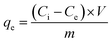 | (1) |
The removal efficiency of RB was calculated by the following equation:
| |
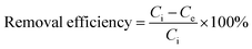 | (2) |
where
Ci is the initial concentration (mg L
−1) of RB,
Ce is the final or equilibrium concentration (mg L
−1) of RB,
V is the total volume of the solution (L),
m is the dosage of MHCM (g) and
qe is the amount of RB adsorbed per unit weight of MHCM (mg g
−1).
The effects of the initial pH, dosage of MHCM, initial dye concentration and adsorption time on the decolourization ability were studied. The pH in these experiments was the original pH of the dye solutions unless mentioned specifically.
3. Results and discussion
3.1 Synthesis of the MHCMs
The synthesis procedure of the MHCMs is presented in Scheme 1. The Fe3O4/PS microspheres were fabricated through a surfactant-free emulsion polymerization, as reported in our previous work.28 A PF shell was coated on the Fe3O4/PS via a microwave-assisted condensation polymerization, resulting in double PS/PF shells. The Fe3O4/PS/PF was coated by another PS shell through a surfactant-free seeded emulsion polymerization and Fe3O4/PS/PF/PS microspheres were obtained. Subsequently, the Fe3O4/PS/PF/PS microspheres were coated by a PF shell using a microwave-assisted approach and Fe3O4/PS/PF/PS/PF microspheres with an alternate multilayer structure of PS and PF shells were formed. The as-fabricated Fe3O4/PS/PF/PS/PF microspheres were carbonized at 650 °C under a nitrogen flow. In the carbonization process, the PS shells were eliminated and the PF layers become porous carbon shells by thermolysis. Thus, a hollow space was formed between the porous carbon shells and the magnetic Fe3O4 core.
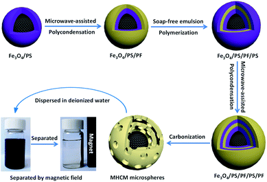 |
| | Scheme 1 Synthetic procedure of the MHCMs and their magnetic separation from aqueous solution. | |
The TEM images of the Fe3O4/PS microspheres are displayed in Fig. 1. It can be seen that the Fe3O4 nanoparticles were encapsulated by a PS shell with an average size of 580 nm. The TEM images of the Fe3O4/PS/PF, Fe3O4/PS/PF/PS, Fe3O4/PS/PF/PS/PF and MHCM composites microspheres are shown in Fig. 2. From the images, it could be found that all the microspheres were monodispersed, spherical in shape and uniform in size. The size of Fe3O4/PS/PF, Fe3O4/PS/PF/PS and Fe3O4/PS/PF/PS/PF was 890 nm, 1092 nm and 1323 nm, respectively. The increase in size proved the successful coating of the PF and PS shells. It could be clearly observed that the MHCM was of a multilayer hollow structure with a Fe3O4 core and alternating cavities and porous carbon shells. The size of the MHCM was 1180 nm. Its inner carbon shell was 130 nm and the outer carbon shell was 100 nm. The uniform core/shell structure and well-defined multilayer hollow structure of the microspheres indicated the microwave-assisted polycondensation for the PF coating, and showed that the approach to conversion of the product to hollow microspheres was facile and efficient for controlling the construction of a multilevel microstructure.
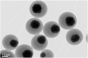 |
| | Fig. 1 TEM image of the Fe3O4/PS microspheres. | |
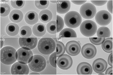 |
| | Fig. 2 TEM images of the (a) Fe3O4/PS/PF, (b) Fe3O4/PS/PF/PS, (c) Fe3O4/PS/PF/PS/PF and (d) MHCM microspheres. | |
3.2 Characterization of the MHCMs
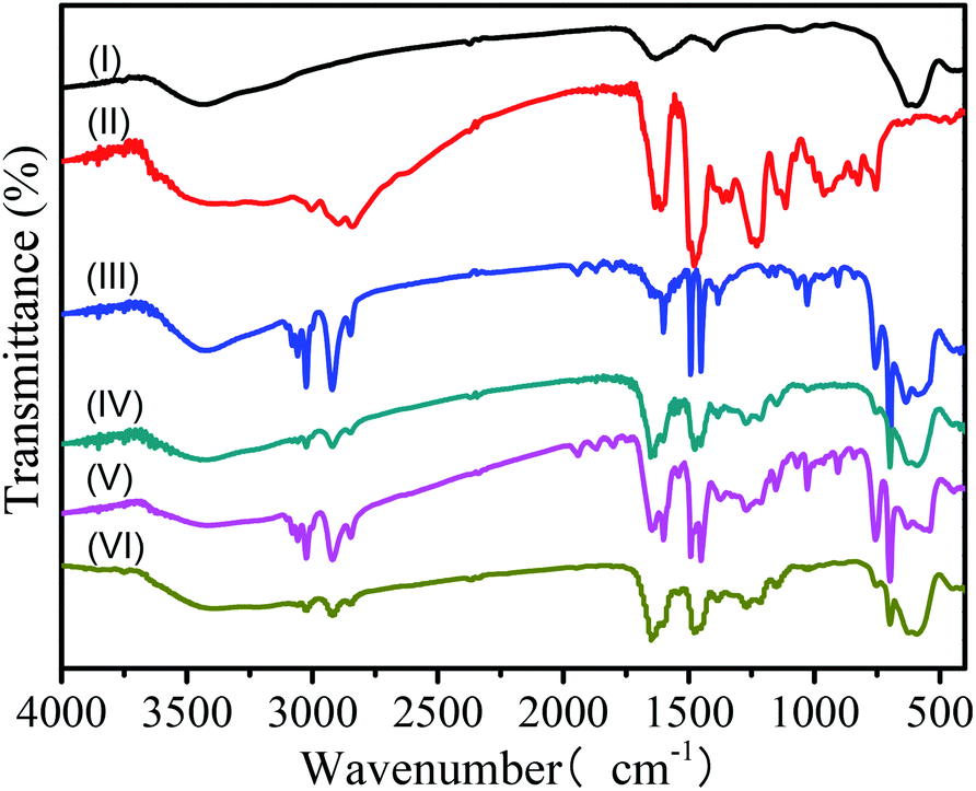
To confirm the coating of PF and PS shells, the samples Fe3O4, PF particles, Fe3O4/PS, Fe3O4/PS/PF, Fe3O4/PS/PF/PS and Fe3O4/PS/PF/PS/PF were characterized by FT-IR spectroscopy (Fig. 3). The FT-IR spectroscopy results of the Fe3O4 nanoparticles and PF particles were characterized as the controls (Fig. 3I and II). It was observed that the Fe3O4/PS spectra (Fig. 3III) showed characteristic adsorption peaks in the ranges of 3009–3092 cm−1 and 1640–1495 cm−1, which were attributed to the C–H bonds of the benzene ring. The stretching of the C–H bonds of the saturated alkane from the PS shell could be identified at 2848 cm−1 and 2918 cm−1. The three adsorption peaks at 1600, 1496 and 1447 cm−1 were due to the vibration of C–C bonds in the benzene ring. The strong rocking modes of CH2 found at 757 cm−1 and 701 cm−1 were from the single substituted benzene ring.30,31 These indicated the existence of PS shells. Compared with the spectrum of Fe3O4 (Fig. 3I), the adsorption peak at 582 cm−1 was the characteristic absorption of Fe–O bonds, which confirmed the presence of Fe3O4 nanoparticles.31 The FT-IR spectrum of Fe3O4/PS/PF microspheres (Fig. 3IV) had additional characteristic absorption of phenolic O–H at 1385 cm−1, and C–O stretching at 1275 cm−1 and 1140 cm−1, which originated from the PF shells (compared with the spectrum of PF in Fig. 3II).32 Compared with the spectra of Fe3O4/PS/PF, the characteristic peaks of PS shells were obviously enhanced in the spectra of Fe3O4/PS/PF/PS (Fig. 3V), thus this suggested that the PS shells were coated onto the Fe3O4/PS/PF microspheres. The characteristic peaks of Fe3O4, PS and PF shells were found in the spectrum of the Fe3O4/PS/PF/PS/PF microspheres (Fig. 3VI). Moreover, the characteristic absorption of PS shells was reduced, but the characteristic peak absorption of PF shells was enhanced, implying the formation of a second layer of PF shells. The results confirmed that Fe3O4, PS and PF are components of the Fe3O4/PS/PF/PS/PF microspheres and suggested the formation of a multilayer structure.
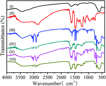 |
| | Fig. 3 FT-IR spectra of (I) Fe3O4 nanoparticles, (II) PF particles, (III) Fe3O4/PS microspheres, (IV) Fe3O4/PS/PF microspheres, (V) Fe3O4/PS/PF/PS and (VI) Fe3O4/PS/PF/PS/PF. | |
The thermal stability and the composition of the Fe3O4 nanoparticles, PF, Fe3O4/PS and Fe3O4/PS/PF/PS/PF microspheres were characterized by TGA in a nitrogen atmosphere (Fig. 4). A 21% weight loss for Fe3O4 nanoparticles was found due to the thermolysis of the citrate stabilizer on the nanoclusters (Fig. 4a).20 Fig. 4b shows that the PS was completely decomposed at 530 °C. The TGA curve presents the existence of two thermal degradation ranges in pyrogenation of the PF particles (Fig. 4c), which can be explained by water removal during condensation and by the carbonization of PF. This was similar to the reported cases in the literature.29,32 Compared with the TGA curves of Fe3O4, PS and PF, the decomposing of the Fe3O4/PS/PF/PS/PF microspheres included elimination of the PS shells and carbonization of the PF shells (Fig. 4d). A 3.7% weight loss occurred between 100 °C and 345 °C. This involved water condensation and volatilization of the unreacted oligomers. When the temperature rose from 345 °C to 669 °C, a 49.2% weight loss occurred, this was caused by the elimination of various volatiles derivatives.28,29 This progress included thermal decomposition of the PS shells and carbonization of the PF shells. The third weight loss stage was above 669 °C due to continuing carbonization of the PF shells.
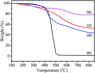 |
| | Fig. 4 TGA curves of (a) Fe3O4, (b) PS, (c) PF particles and (d) Fe3O4/PS/PF/PS/PF microspheres. | |
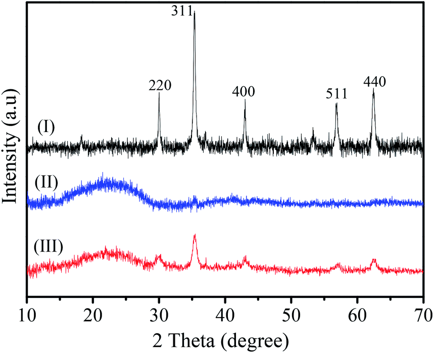
The crystalline structure of MHCMs was characterized by powder X-ray diffraction (XRD), as shown in Fig. 5. The Fe3O4 and porous PF carbon were applied as controls. It was obvious the typical diffraction peaks at 220, 311, 400, 511 and 440 of the Fe3O4 particles appeared in the XRD pattern of the MHCMs. This suggested that the crystalline structure of Fe3O4 particles was well retained under the whole fabrication process. In addition, a broad peak presented at 2θ = 16–28°, which was derived from the amorphous phase of the PF carbon shells (compared with Fig. 5II). The above results confirmed that magnetic Fe3O4 particles were coated onto the carbon shells.
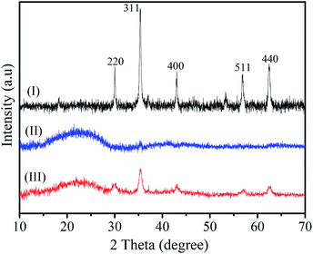 |
| | Fig. 5 XRD patterns of (I) Fe3O4 particles, (II) porous PF carbon nanospheres and (III) MHCMs. | |
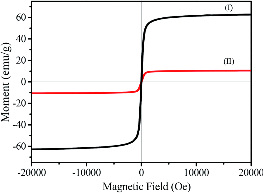
The magnetic hysteresis curves are shown in Fig. 6. The magnetic Fe3O4 clusters are a typical superparamagnetic material and present a high saturation magnetization (Ms) of 62.9 emu g−1. As seen in Fig. 6II, the as-synthesized MHCM microspheres presented good superparamagnetic properties (Ms = 10.3 emu g−1). Compared with the magnetic hysteresis curve of Fe3O4, it showed that the MHCM was a superparamagnetic material. The MHCMs could rapidly respond to the magnetic field and could easily be separated from the aqueous solution within 1 min (Scheme 1).
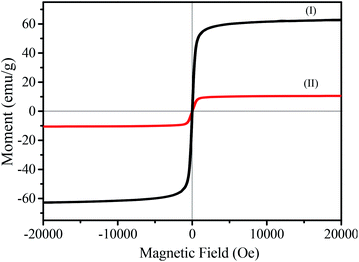 |
| | Fig. 6 Magnetic hysteresis curves of (I) magnetic Fe3O4 clusters; (II) MHCMs. | |
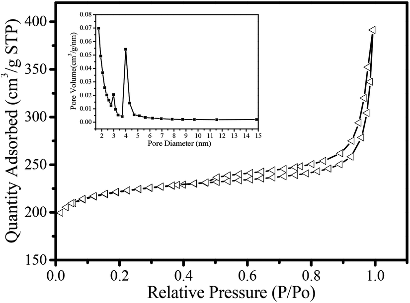
Nitrogen adsorption/desorption isotherms of the MHCM carbon microspheres are shown in Fig. 7. The sorption isotherm plot of the MHCMs was a combination of types I and IV, corresponding to micro-mesoporous materials according to the IUPAC classification. This showed the existence of different pore sizes in the hybrid spheres. The steep increase and high adsorbed volume (200 cm3 g−1) at low relative pressure was related to the presence of micropores, which were formed during the carbonization. The BET surface area of the MHMCs was 680 m2 g−1. The adsorption average pore width was 3.5 nm and the single point adsorption total pore volume at P/P0 = 0.99 was 0.61 cm3 g−1. The t-plot micropore volume was 0.31 cm3 g−1 and the Barrett–Joyner–Halenda desorption cumulative volume of pores was 0.33 cm3 g−1. Moreover, the almost vertical tails near to P/P0 = 0.99 suggested the presence of macroporosity generated by removal of the PS template and carbonization of the PF shells. The pore-size distribution was evaluated using the BJH model. The MHCMs possessed dual narrow mesoporous size distributions near 2.9 nm and 4.0 nm, respectively (the inset in Fig. 7). The unique pore properties and multilayer hollow structure of the MHCMs can be expected to be advantageous for applications in adsorption, separation and bioenrichment.
 |
| | Fig. 7 Nitrogen adsorption/desorption isotherms of MHCM microspheres. The inserted was the pore-size distribution. | |
3.3 Removal of rhodamine B (RB) in aqueous solution
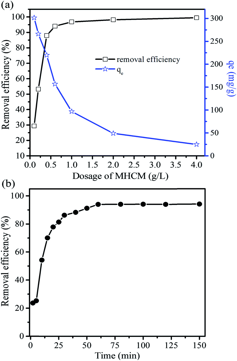
3.3.1 Effect of MHCM dosage on RB removal. The removal of RB by different dosages of MHCMs was studied. Fe3O4 nanoparticles and single-carbon-layer mesoporous carbon microspheres (SLCM) were studied as controls. The results (Fig. 8a) showed that the removal efficiency of RB increased sharply as the dosage of MHCMs increased, due to the increase in porous active bonding sites, and reached a peak value of 99.5% when the dosage was over 2.0 g L−1. The adsorption capacity (qe) of the MHCMs reached as high as 300 mg g−1 when the dosage was 0.1 g L−1. It was found the RB could hardly be removed by Fe3O4 nanoparticles (Fig. S1 in the ESI†). At the same condition, the single-carbon-layer mesoporous carbon microspheres (SLCMs), which possessed a BET surface area of 331.5 m2 g−1 and narrow mesoporous size distributions at 4.0 nm (Fig. S2†), removed 71% of the RB with a dosage over 2.0 g L−1, albeit the removal efficiency was much lower than the MHCMs. Moreover, qe of the SLCM was 177.4 mg g−1 when the dosage was 0.1 g L−1 (Fig. S3a†), which was much lower than the MHCMs. The higher RB removal performance was caused by the larger BET surface area, unique pore properties and sandwich-like hollow structure (double porous carbon layers) of the MHCMs.
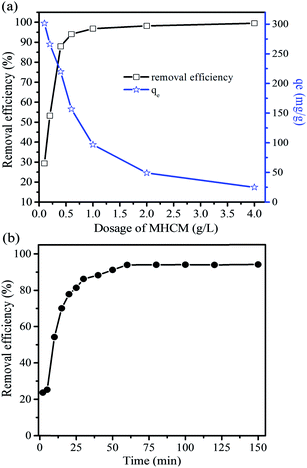 |
| | Fig. 8 (a) Effect of the dosage of MHCMs on the removal efficiency (RB concentration 100 mg L−1, temperature 25 °C, pH = 7 and adsorption time 120 min); (b) effect of contact time on the decolourization efficiency (RB concentration 100 mg L−1, dosage of MHCMs 0.6 g L−1, pH = 7 and temperature 25 °C). | |
3.3.2 Effect of contact time on the removal efficiency. As the results show in Fig. 8b, the adsorption capacity initially increased with the increase in time and then kept at a constant value thereafter. More than 94% of the dye was removed within 60 min and the reaction reached equilibrium in 80 min. According to the slope of the curve, the sample exhibited a fast removal rate for RB in the initial stage, and the removal of RB could reach 70% in the first 15 min. When further prolonging the reaction time, the adsorption rate became obviously slower and equilibrium was reached in 80 min. The rapid uptake of RB by MHCMs indicated a fast binding kinetics occurring in this process.
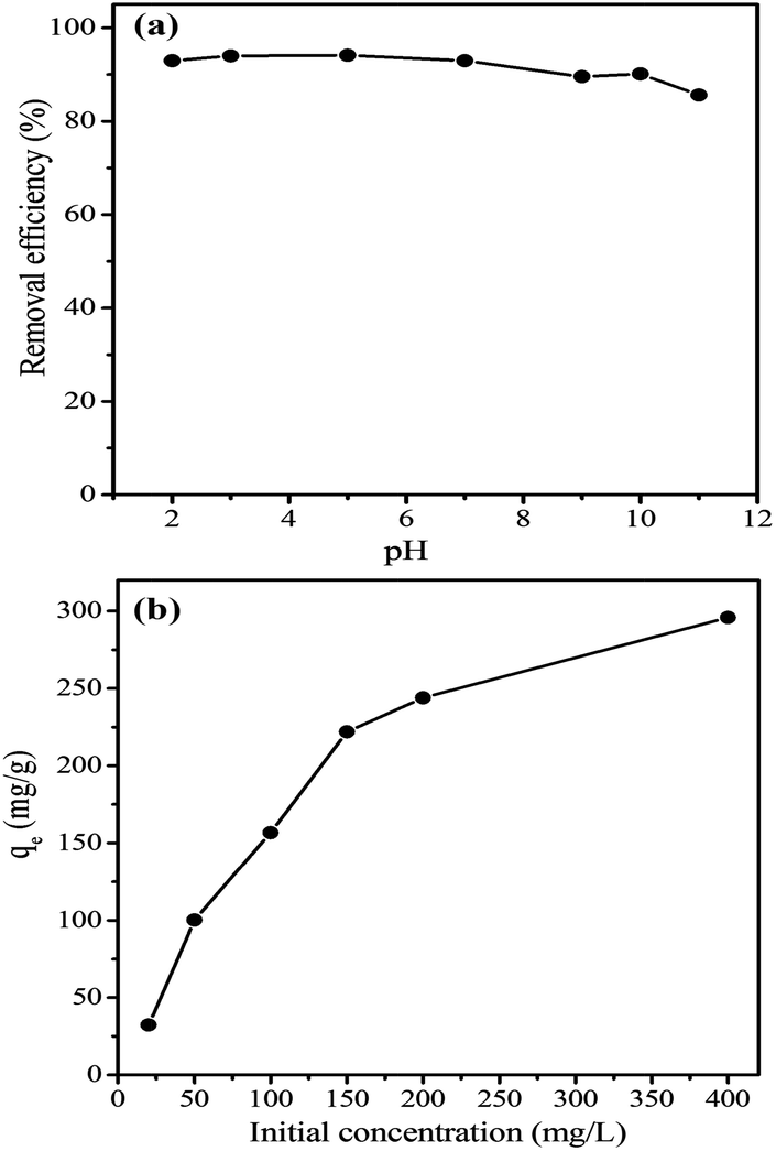
3.3.3 Effect of initial pH on the removal efficiency. Generally, the impact of pH is very important because it has tremendous effects on the surface properties of adsorbates and adsorbents.33,34 To investigate the effect of the initial pH on the removal of RB, a series of experiments with different initial solution pHs in range of 2–11 was carried out. As shown in Fig. 9a, the MHCMs removed over 90.2% of RB at pH 2–10 and 86% at pH = 11, which suggested that the MHCMs could remove organic dyes efficiently over a wide pH range. When the pH was over 8, the removal efficiency slightly decreased as the pH increased, which may be caused by the existence of excess OH− ions competing with RB for the adsorption sites. The efficient elimination of RB over a wide pH range shows the MHCMs are beneficial for use in practical applications.
 |
| | Fig. 9 (a) Effect of initial pH on the removal efficiency (RB concentration 100 mg L−1, dosage of MHCMs 0.6 g L−1, temperature 25 °C and adsorption time 120 min); (b) effect of the initial dye concentration (temperature 25 °C, adsorption time 120 min, dosage of MHCMs 0.6 g L−1, pH = 7). | |
3.3.4 Effect of initial RB concentration. The adsorption capacity versus the initial RB concentration is presented in Fig. 9b. The SLCM was used to remove various initial concentrations of RB as comparisons. It was observed that an increase in the initial RB concentration led to an increase in the amount of RB adsorbed per unit weight of MHCM. A higher concentration resulted in a higher driving force of the concentration gradient.7,33 This driving force accelerated the diffusion of RB molecules from the solution into the adsorbent and decreased the resistance to the uptake of the RB.9 As the initial concentration increased from 20 to 400 mg L−1, the amounts of RB adsorbed on the adsorbent increased from 32.2 to 295.9 mg g−1. The same phenomenon was observed in the case of SLCM, but the amounts of RB adsorbed on the SLCM increased from 13.0 to 152.6 mg g−1 (Fig. S3b†), which was much lower than with the MHCMs. The results indicated that the design of double porous carbon layers and a sandwich-like hollow structure made the MHCMs possess enhanced high adsorption efficiency.
3.4 Evaluation of adsorption isotherm models
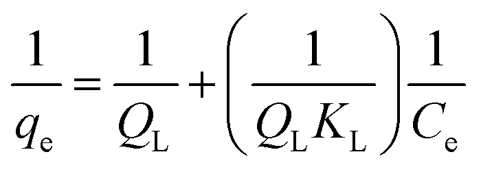
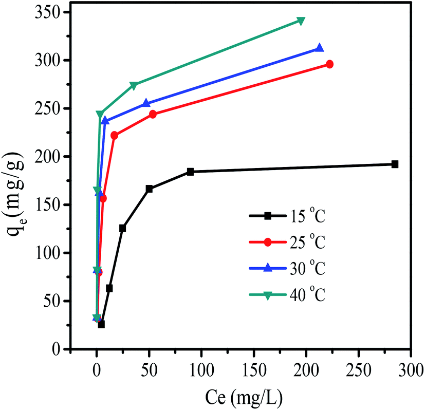
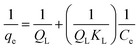
The adsorption isotherms of RB at various temperatures are shown in Fig. 10. The Langmuir, Freundlich and Dubinin–Radushkevich isotherms were tested for the equilibrium description.35,36 The Langmuir isotherm is represented by the following equation:37| |
 | (3) |
where qe (mg g−1) is the amount of RB adsorbed by per unit weight of MHCM, Ce (mg L−1) is the equilibrium concentration of the RB, QL (mg L−1) is the maximum monolayer adsorption capability and KL (L mg−1) is a constant related to the free energy of adsorption.
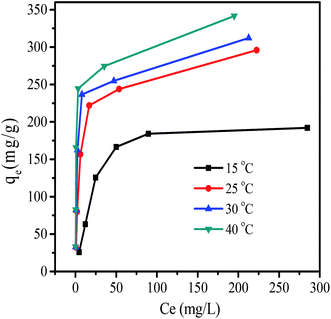 |
| | Fig. 10 Adsorption isotherms of RB at various temperatures by MHCMs (dosage of MHCMs 0.6 g L−1, pH = 7, adsorption time 120 min, RB concentration 20, 50, 100, 150, 200 and 400 mg L−1, respectively.). | |
The well-known Freundlich isotherm is often used for heterogeneous surface energy systems.38 The Freundlich equation is presented as:
| |
 | (4) |
The Dubinin–Radushkevich (D–R) isotherm is a more general isotherm because it does not assume a homogeneous surface or constant adsorption potential.39 The D–R isotherm equation is as follows:
| |
ln![[thin space (1/6-em)]](https://www.rsc.org/images/entities/char_2009.gif) qe = lnQD − βε2 qe = lnQD − βε2
| (5) |
where
β (mg
2 kJ
−2) is a constant related to the mean free energy of adsorption per mole of the adsorbate.
QD (mg g
−1) is the theoretical saturation capacity and
ε is the Polanyi potential, which is equal to
ε = −
RTln(1 + 1/
Ce) where
R (
R = 8.314 J mol
−1 K
−1) is the gas constant and
T (K) is the absolute temperature.
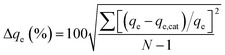
The normalized standard deviation of qe (Δqe) derived from each isotherm is calculated as:
| |
 | (6) |
where
N is the number of data,
qe (mg g
−1) is the experimental value and
qe,cat (mg g
−1) is the calculated value by the isotherm equations.
The isotherm parameters calculated from plots of these isotherm equations are given in Table 1. The Langmuir isotherm model fitted best when the R2 values were compared. The value of QL was almost equal to the experimental equilibrium adsorption capacity (Fig. 10). The correlation coefficients of the Langmuir isotherm were in the range of 0.9961–0.9992. Moreover, the Δqe (%) values calculated by the Langmuir isotherm were lowest and narrowest distributed (4.83–9.77%), which also showed that the adsorption process followed the Langmuir isotherm very well. This indicated that adsorption took place at specific homogenous sites within the adsorbent and that the adsorbed RB molecules were not vertically oriented or strong competition did not exist from the solvent.40 It was found that the Freundlich isotherm equation also described the experimental data well with moderate coefficients (0.9084–0.9824) at various temperatures, but with relatively high Δqe (10.46–17.54%) values. Application of the Freundlich model confirmed that RB adsorption capacity by the MHCMs increased with the temperature, because the value of KF increased with the temperature. It was observed that the D–R isotherm (0.84 < R2 < 0.94) did not adequately fit the experimental values. The low coefficients indicated that the removal of RB could not be described by the D–R isotherm. The high and wide distributed Δqe values also showed the removal process did not follow the D–R isotherm.
Table 1 Isotherms parameters of RB adsorption by MHCMs at various temperatures
| T (K) |
Langmuir |
Freundlich |
D–R isotherm |
| QL (mg g−1) |
KL (L mg−1) |
R2 |
Δqe (%) |
KF (L mg−1) |
n |
R2 |
Δqe (%) |
QD (mg g−1) |
β (mg2 kJ−2) |
R2 |
Δqe (%) |
| 288.15 |
212.7 |
0.2999 |
0.9974 |
9.77 |
10.547 |
1.479 |
0.9287 |
10.46 |
196.4 |
87.42 |
0.9152 |
30.95 |
| 298.15 |
277.8 |
0.2081 |
0.9992 |
4.83 |
47.12 |
1.684 |
0.9084 |
13.50 |
218.4 |
1.081 |
0.9404 |
12.95 |
| 303.15 |
312.5 |
0.5000 |
0.9987 |
9.06 |
85.56 |
1.801 |
0.9172 |
17.54 |
248.1 |
0.2022 |
0.8857 |
19.23 |
| 313.15 |
344.8 |
0.5918 |
0.9961 |
7.46 |
113.82 |
1.508 |
0.9824 |
11.19 |
221.6 |
0.0842 |
0.8411 |
22.28 |
3.5 Thermodynamic parameters
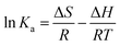
The thermodynamic equilibrium parameters, such as free energy change (ΔG), enthalpy change (ΔH) and entropy change (ΔS), can be determined by the following equations:| | |
ΔG = −RTlnKa
| (7) |
| |
 | (8) |
The plot of lnKa as a function of 1/T yields a straight line from which ΔH and ΔS were calculated from the slope and intercept, respectively. T is the absolute temperature (in Kelvin); R is the universal gas constant (8.314 J mol−1 K−1). The constant Ka was determined by plotting ln(qe/Ce) versus qe and extrapolating zero qe.39 The results are given in Table 2.
Table 2 Thermodynamic parameters of RB removal by MHCMs
| T (K) |
Ka (L g−1) |
ΔG (kJ mol−1) |
ΔH (kJ mol−1) |
ΔS (J (mol−1 K−1)) |
| 288.15 |
79.69 |
−10.49 |
28.35 |
134.35 |
| 298.15 |
103.86 |
−11.51 |
| 303.15 |
134.83 |
−12.36 |
| 313.15 |
202.82 |
−13.83 |
The ΔG of the adsorption process was negative. This indicated that the adsorption was a spontaneous process.8 The absolute value of ΔG increased as the temperature increased, suggesting that higher temperature was favourable for RB removal. The positive value of ΔH (28.35 kJ mol−1) showed that the RB removal process by MHCMs was endothermic and was favoured at higher temperature.36 The ΔS in the adsorption process was 134.35 J (mol−1 K−1). The positive entropy change (ΔS) value for adsorption corresponded to an increase in the degree of randomness of the adsorbed species.38
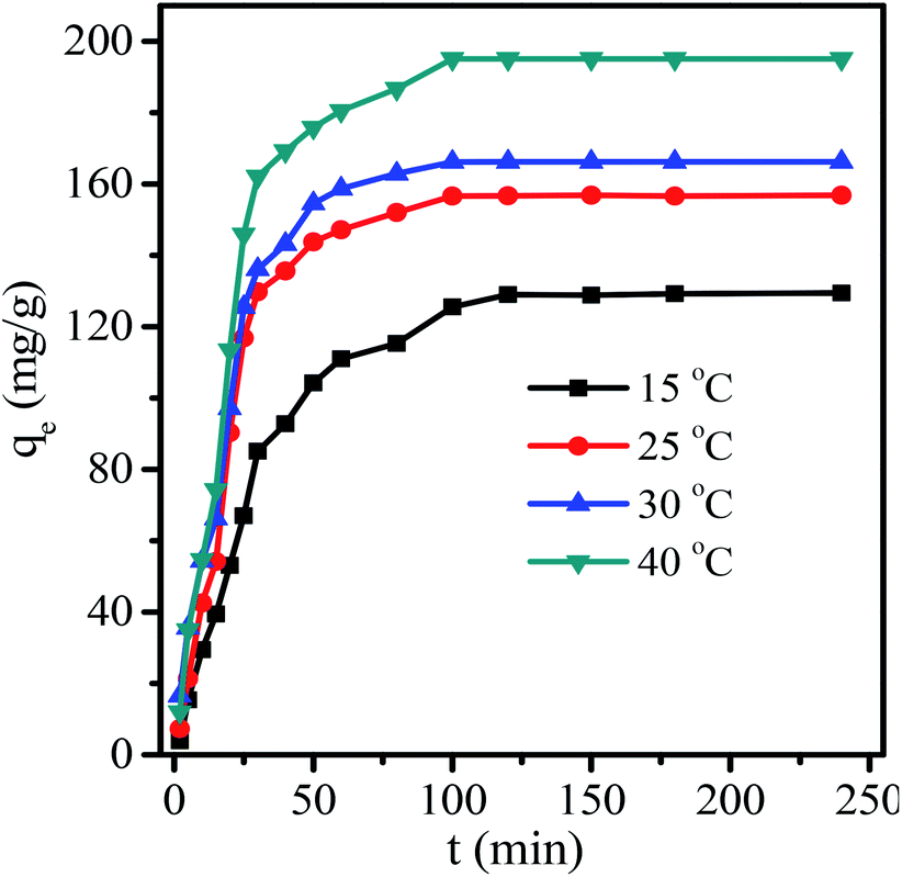
3.6 Adsorption kinetics
Information on the kinetics of pollutant uptake is required for an insight into the adsorption mechanism and for selecting the optimum operating conditions. According to Fig. 11, a higher temperature led to a faster rate and all the curves finally reached equilibrium in 80 min. The adsorption kinetics of uptake of RB onto MHCMs was studied by fitting the pseudo-first-equation and the pseudo-second-order equation. The pseudo-first-order rate model is described as:33| | |
ln(qe − qt) = lnqe − k1t
| (9) |
where qe is the amount of solute adsorbed at equilibrium per unit weight of adsorbent (mg g−1), qt is the amount of solute adsorbed at any time (mg g−1) and k1 is the adsorption constant.
 |
| | Fig. 11 Kinetic curves for RB removal by MHCMs (RB concentration 100 mg L−1, dosage of MHCMs 0.6 g L−1, pH = 7). | |
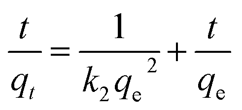
The pseudo-second-order equation can be represented as:34
| |
 | (10) |
where
k2 (g mg
−1 min
−1) is the second-order rate constant and
qt is the amount adsorbed at time
t. The pseudo-first-order kinetic plots and pseudo-second-order kinetic plots are presented in Fig. S4 and S5 in the ESI.
† The values of
k1,
k2 and the corresponding correlation coefficients (
R2) are summarized in
Table 3.
Table 3 Kinetic parameters for RB adsorption by MHCMs
| T K |
Pseudo-first-order equation |
Pseudo-second-order equation |
| k1 min−1 |
qe mg g−1 |
R2 |
k2 g (mg−1 min−1) |
qe mg g−1 |
R2 |
| 288.15 |
0.0384 |
156.28 |
0.8523 |
0.353 |
142.86 |
0.9853 |
| 298.15 |
0.0402 |
111.90 |
0.9034 |
0.377 |
161.29 |
0.9957 |
| 303.15 |
0.0698 |
270.20 |
0.9496 |
0.386 |
175.44 |
0.9928 |
| 313.15 |
0.0786 |
468.15 |
0.9145 |
0.418 |
200.00 |
0.9939 |
The R2 values (0.8523 < R2 < 0.9496) showed that the pseudo-first-order kinetics did not adequately fit the experimental values. The pseudo-second-order kinetic model described all the adsorption processes very well according to the correlation coefficients, of which the correlation coefficients were above 0.9853. Moreover, the equilibrium qe obtained from this model was closely in line with the experimental value. The well-fitting of the pseudo-second-order equation suggested that the adsorption process was interaction controlled.40,41
The insight of activation energy may give an idea about the type of adsorption. The activation energy of RB absorption by MHCMs was determined using the Arrhenius equation:41–43
| |
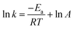 | (11) |
where
Ea is activation energy,
R is the gas constant (8.314 J (mol
−1 K
−1)),
T is the temperature in Kelvin,
k is the adsorption rate constant and
A is the frequency factor. The value of
Ea can be determined from the slope of lnk
versus 1/
T plot (the plot of lnk
vs. 1/
T is shown in Fig. S6 in the ESI
†).
The adsorption rate constants according to the pseudo-second-order kinetic model at various temperatures were used to calculate the activation energy value. Generally, the activation energy in a physical adsorption is below 4.2 kJ mol−1 and chemical adsorption involves forces much stronger than that of physical adsorption.42 The activation energy (Ea) of the adsorption process was 5.04 kJ mol−1, which indicated the dominant physical adsorption mechanism accompanied by the existence of chemisorption.
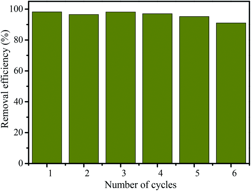
3.7 Reusability of MHCMs for RB removal
The regeneration and reusability of adsorbents are very important in their industrial applicability. In order to study the reusability of the MHCMs as an adsorbent, recycling experiments were conducted with each cycle of 60 min contact time using 2 g L−1 MHCMs dosage. After each cycle, the MHCMs were separated by a magnet and regenerated by treatment with 1.0 mol L−1 sodium hydroxide and heated at 400 °C for 1.0 h in nitrogen. As shown in Fig. 12, after six consecutive cycles, the removal efficiency of RB still remained over 90%. This demonstrated the high regeneration capability of MHCMs and their good reusability for RB removal. The results revealed that the MHCMs were a favourable reusable adsorbent for the removal of RB from aqueous solutions.
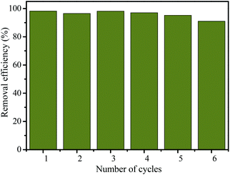 |
| | Fig. 12 Recycling of MHCMs for the removal of RB from actual solutions (RB concentration 100 mg L−1, dosage of MHCMs 2.0 g L−1, temperature 25 °C and contact time 60 min). | |
4. Conclusions
Porous magnetic hollow carbon microspheres (MHCMs) were fabricated by a combination of microwave-assistant polycondensation and surfactant-free emulsion polymerization. The MHCMs possessed uniform morphologies, high surface areas, large pore volume and magnetic responsiveness. The BET surface area of the MHMCs was as high as 680 m2 g−1 with a total pore volume of 0.61 cm3 g−1. The adsorption of RB by MHCMs was studied in aqueous solution. With a dosage of 2.0 g L−1, the removal efficiency of RB (100 mg L−1) reached 99.5%. The adsorption capacity of the MHCMs reached as high as 300 mg g−1 when the dosage was 0.1 g L−1. The adsorption process followed the Langmuir isotherm very well with very high correlation coefficient values (0.9961–0.9992) and low normalized standard deviation Δqe values (4.83–9.77%). The adsorption kinetics fitted well with a pseudo-second-order kinetics model. The activation energy (Ea) of the adsorption process was 5.04 kJ mol−1. After six consecutive cycles, the removal efficiency of RB still remained over 90%. These results indicated the promising application of MHCMs as a high performance reusable adsorbent.
Acknowledgements
We gratefully acknowledge the financial support of the National Natural Science Foundation of China (Grant No. 51503040 and 31401609), the Talent Fund of Fuzhou University (Grant No. XRC-1462), and the Natural Science Foundation of Fujian province (Grant No. 2016J01733).
Notes and references
- P. Niu and J. Hao, Colloids Surf., A, 2014, 443, 501–507 CrossRef CAS.
- G. Das, T. Skorjanc, T. Prakasam, S. Nuryyeva, J. C. Olsen and A. Trabolsi, RSC Adv., 2017, 7, 3594–3598 RSC.
- E. Emilia Rios-Del Toro, L. B. Celis, F. J. Cervantes and J. Rene Rangel-Mendez, J. Hazard. Mater., 2013, 260, 967–974 CrossRef CAS PubMed.
- C. Yang, S. Wu, J. Cheng and Y. Chen, J. Alloys Compd., 2016, 687, 804–812 CrossRef CAS.
- C. Cai, H. Zhang, X. Zhong and L. W. Hou, Water Res., 2014, 66, 473–485 CrossRef CAS PubMed.
- M. Mohammadi, A. J. Hassani, A. R. Mohamed and G. D. Najafpour, J. Chem. Eng. Data, 2010, 55, 5777–5785 CrossRef CAS.
- H. Liu, X. Ren and L. Chen, J. Ind. Eng. Chem., 2016, 34, 278–285 CrossRef CAS.
- L. You, F. Lu, L. Song, Y. Yin and Q. Zhang, RSC Adv., 2015, 5, 64711–64723 RSC.
- S. K. Giri, N. N. Das and G. C. Pradhan, Colloids Surf., A, 2011, 389, 43–49 CrossRef CAS.
- J. Ma, D. Huang, W. Zhang, J. Zou, Y. Kong, J. Zhu and S. Komarneni, Chemosphere, 2016, 162, 269–276 CrossRef CAS PubMed.
- S. Kaur, V. Bhalla and M. Kumar, ACS Appl. Mater. Interfaces, 2015, 7, 16617–16624 CAS.
- I. Zawierucha, C. Kozlowski and G. Malina, Environ. Sci.: Processes Impacts, 2016, 18, 429–444 CAS.
- Y. Wu, M. Zhang, H. Zhao, S. Yang and A. Arkin, RSC Adv., 2014, 4, 61256–61267 RSC.
- Y. Y. Qu, X. Y. Cao, Q. Ma, S. G. Shi, L. Tan, X. L. Li, H. Zhou, X. W. Zhang and J. T. Zhou, J. Hazard. Mater., 2012, 223–224, 31–38 CrossRef CAS PubMed.
- B. V. Mohite, V. Bhavna and S. V. Patil, J. Biomater. Sci., Polym. Ed., 2014, 25, 2053–2065 CrossRef CAS PubMed.
- J. P. Jadhav, G. K. Parshetti, S. D. Kalme and S. P. Govindwar, Chemosphere, 2007, 68, 394–400 CrossRef CAS PubMed.
- T. Chen, B. Y. Gao and Q. Y. Yue, Colloids Surf., A, 2010, 355, 121–129 CrossRef CAS.
- R. Sanghi and P. Verma, Color. Technol., 2013, 129, 85–108 CAS.
- P. Patricio, M. P. Cláudia, R. L. T. Elaine, G. M. Sandra, A. R. Maria, C. M. Rosana and D. Nelson, Appl. Catal., B, 2003, 42, 131–144 CrossRef.
- L. You, Y. Zhang, S. Xu, J. Guo and C. Wang, ACS Appl. Mater. Interfaces, 2014, 6, 15179–15187 CAS.
- M. Dai, L. Xia, S. Song, C. Peng and A. Lopez-Valdivieso, J. Hazard. Mater., 2016, 281, 312–317 CrossRef PubMed.
- J. Feng, J. Gong, X. Wen, N. Tian, X. Chen, E. Mijowska and T. Tang, RSC Adv., 2014, 4, 26817–26823 RSC.
- L. D. Virla, V. Montes, J. Wu, S. F. Ketep and J. M. Hill, Microporous Mesoporous Mater., 2016, 234, 239–247 CrossRef CAS.
- Z. Wang, F. Zhang, Y. Lu, B. Zhai, S. Zhai, Z. Xiao, Q. An, C. Yu and S. Gao, Mater. Res. Bull., 2016, 83, 590–596 CrossRef CAS.
- C. Liang, Z. Li and S. Dai, Angew. Chem., Int. Ed., 2008, 47, 3696–3717 CrossRef CAS PubMed.
- P. Adelhelm, Y. S. Hu, L. Chuenchom, M. Antonietti, B. M. Smarsly and J. Maier, Adv. Mater., 2007, 19, 4012–4017 CrossRef CAS.
- S. Zeng, S. Duan, R. Tang, L. Li, C. Liu and D. Sun, Chem. Eng. J., 2014, 258, 218–228 CrossRef CAS.
- S. Xu, W. Ma, L. You, J. Li, J. Guo, J. J. Hu and C. Wang, Langmuir, 2010, 28, 3271–3278 CrossRef PubMed.
- L. You, S. Xu, W. Ma, D. Li, Y. Zhang, J. Guo, J. J. Hu and C. Wang, Langmuir, 2012, 28, 10565–10572 CrossRef CAS PubMed.
- X. Y. Dai, X. Zhang, Y. F. Meng and P. K. Shen, New Res. Carbon Mater., 2011, 26, 389–395 CrossRef CAS.
- R. Y. Hong, B. Feng, G. Liu, S. Wang, H. Z. Li, J. M. Ding, Y. Zheng and D. G. Wei, J. Alloys Compd., 2009, 476, 612–618 CrossRef CAS.
- C. F. Martín, M. G. Plaza, S. García, J. J. Pis, F. Rubiera and C. Pevida, Fuel, 2011, 90, 2064–2072 CrossRef.
- S. Chaudhary, P. Sharma, Renu and R. Kumar, RSC Adv., 2016, 6, 62797–62809 RSC.
- D. Li, D. Chen, Y. Yao, J. Lin, F. Gong, L. Wang, L. Luo, Z. Huang and L. Zhang, Chem. Eng. J., 2016, 288, 806–812 CrossRef CAS.
- L. Ding, B. Zou, W. Gao, Q. Liu, Z. Wang, Y. Guo, X. Wang and Y. Liu, Colloids Surf., A, 2014, 446, 1–7 CrossRef CAS.
- G. Zhou, C. Liu, Y. Tang, S. Luo, Z. Zeng, Y. Liu, R. Xu and L. Chu, Chem. Eng. J., 2015, 280, 275–282 CrossRef CAS.
- F. Zhao, E. Repo, D. Yin and M. E. Sillanpaa, J. Colloid Interface Sci., 2013, 409, 174–182 CrossRef CAS PubMed.
- M. Mohammadi, A. J. Hassani, A. R. Mohamed and G. D. Najafpour, J. Chem. Eng. Data, 2010, 55, 5777–5785 CrossRef CAS.
- A. S. Ozcan, B. Erdem and A. Ozcan, Colloids Surf., A, 2005, 266, 73–81 CrossRef.
- Q. Li, Q. Yue, H. Sun, Y. Su and B. Gao, J. Environ. Manage., 2010, 91, 1601–1611 CrossRef CAS PubMed.
- L. You, L. Song, F. Lu and Q. Zhang, Polym. Eng. Sci., 2016, 56, 1213–1220 CAS.
- H. Ucun, Y. K. Bayhan and Y. Kaya, J. Hazard. Mater., 2008, 153, 52–59 CrossRef CAS PubMed.
- E. Oguz, Colloids Surf., A, 2005, 252, 121–128 CrossRef CAS.
Footnote |
| † Electronic supplementary information (ESI) available: Fig. S1 pseudo-first-order kinetic plots of RB removal by MHCM; Fig. S2 pseudo-second-order kinetic plots of RB removal by MHCM; Fig. S3 the plot of lnk vs. 1/T. See DOI: 10.1039/c7ra03045b |
|
| This journal is © The Royal Society of Chemistry 2017 |
Click here to see how this site uses Cookies. View our privacy policy here. 
 Open Access Article
 This Open Access Article is licensed under a Creative Commons Attribution-Non Commercial 3.0 Unported Licence
 *a,
Jiabing Wanga and
Qiqing Zhang*a
*a,
Jiabing Wanga and
Qiqing Zhang*a