 Open Access Article
Creative Commons Attribution 3.0 Unported Licence
Copper-containing porous carbon derived from MOF-199 for dibenzothiophene adsorption†
Guihua Zhaoa,
Yaoyao Fanga,
Wei Dai *a and
Na Mab
aCollege of Chemistry and Life Science, Zhejiang Normal University, Jinhua 321004, Zhejiang Province, People's Republic of China. E-mail: daiwei@zjnu.edu.cn; Fax: +86-579-82282531; Tel: +86-579-82282269
bCollege of Geography and Environmental Science, Zhejiang Normal University, Jinhua 321004, Zhejiang Province, People's Republic of China
First published on 18th April 2017
Abstract
A novel type of copper-containing porous carbon has been synthesized by filling the pores of MOF-199 hard template with furfuryl alcohol as carbon precursor, followed by carbonization and activation for the first time. The textural properties of the as-prepared carbon material were proven by examinations with XRD, SEM, TEM, ICP, XPS and N2 adsorption. The adsorption performance of dibenzothiophene in three types of model oils was investigated by batch tests. The equilibrium data was best represented by the Langmuir isotherm model, showing a maximum monolayer adsorption capacity of 59 μg g−1, which was much higher than some other adsorbents reported in the literature. Considering all the advantages, the as-prepared copper-containing porous carbon shows promising potential for practical deep desulfurization, especially for thiophenic compound removal.
1. Introduction
Nowadays, fuel oils have received more attention due to their high conversion efficiency and low emissions. However, sulfur (S) compounds in fuel oils as environmental pollutants are a major concern owing to their exhaust gases containing SOx, which not only contribute to acid rain but are also harmful to human health.1 Thus, stringent environmental regulations to lower the S-content are continuously being executed in many countries.2 The traditional industrial process is hydro-desulfurization, which is effective for aliphatic and acyclic S-compounds but less effective for thiophenic compounds (e.g. dibenzothiophene, DBT).3,4 To achieve ultradeep desulfurization, some non-HDS alternative methods such as adsorption desulfurization (ADS),5,6 extractive desulfurization (EDS),7,8 oxidative desulfurization (ODS),9,10 biodesulfurization (BDS),11 and others12,13 have been developed.ADS is considered to be one of the most promising methods to overcome the limitations with the traditional hydro-desulfurization process.14–16 Many ADS studies have been undertaken to develop adsorbents using activated carbons,17 zeolites,18 mixed metal oxides,19 and clays.20 Besides, several metal–organic frameworks (MOFs) have been shown promising for ADS,21–23 but organic solvents were generally involved in the synthesis approaches, which were expensive, toxic, and flammable.24,25 Porous MOFs are usually thermally robust and have nanoporous space suitable for small molecules to access and participate in “ship-in-bottle” reactions.25 Therefore, they can reasonably be used as hard templates, similar to mesoporous silica and zeolites, to allow the reactions of small carbon precursors inside the pores, affording porous carbons. Several MOFs have been demonstrated as promising precursors toward porous carbons, and the MOF-derived carbon materials have been considered to be efficient in several adsorption processes such as gas storage and separation.25 However, reports on deep desulfurization by MOF-derived carbon materials with high sulfur capacity are relative scarce.25 MOF-199, a very typical and popular type of MOFs, has been achieved in aqueous solutions, showing great potential for large-scale production.15,26 However, due to its small pore opening or unselective adsorption, MOF-199 was shown to be not very effective for ADS.15 Porous MOF-199 has a permanent nanoscale cavity and open channels offering congenital conditions for small molecules to access and, therefore, exhibits a potential as a template to synthesize nanoporous carbon materials. Thus, we infer that this kind of carbon might be promising for ADS as well.
Hereby, we report the use of MOF-199 as a template for preparing nanoporous carbon (Scheme SI1†). The textural characterization of prepared porous carbon was carried out by SEM, TEM, XRD, ICP, XPS and N2 adsorption experiments. Commercial oil products contain different portions of aromatic components, therefore, three simulated oils with different amounts of aromatic components were prepared in this study. The desulfurization behavior of the novel desulfurizer was investigated and compared with batch tests at room temperature (25 °C). The equilibriums were fitted to different models then evaluated to study the adsorption process of DBT onto the porous carbon.
2. Experimental
2.1 Adsorbent preparation
2.2 Sample characterization
X-ray diffraction (XRD) data was recorded from a Bruker D8 Advance X-ray Diffractometer with Cu Kα radiation (λ = 1.542 Å). Scanning electron microscopy image (SEM) was obtained from a scanning electron microscope (Philips PW 3040/60) operated at 20 kV. Prior to the observation, the sample was sputter-coated with a gold layer to increase their conductivity. Transmission electron microscopy (TEM) measurements were taken on a JEOL 2010 microscope (Japan) operated at 200 kV; the samples were suspended in ethanol and dropped onto holey carbon film supported on a Cu grid. N2 adsorption–desorption isotherms were measured at −196 °C with a Micromeritics ASAP 2020 analyzer and the samples were degassed in a vacuum at 200 °C for 6 h prior to tests. The Brunauer–Emmett–Teller (BET) method and the Barrett–Joyner–Halenda (BJH) model were utilized to calculate the specific surface areas, the pore volumes and the pore size distributions, respectively. The adsorption branch of N2 isotherm was carried out to calculate the pore size distribution due to tensile strength effect phenomenon in the desorption branch.28 The total pore volumes were estimated from the adsorbed amount at a relative pressure P/P0 of 0.995. Metal contents of the as-synthesized porous carbon was measured by ICP (Inductively Coupled Plasma) atomic emission spectroscopy on a Varian Vista AX CD system. The content of copper in the carbon was investigated by Inductively Coupled Plasma (ICP) atomic spectroscopy (ICP-9000(N + M), Thermo Jarrell-Ash).2.3 Batch adsorption experiments
Three simulated oils were prepared using benzene (99.8%, Sigma-Aldrich) as the representative of aromatic oil (ARO), n-octane (99.8%, Sigma-Aldrich) as the representative of aliphatic oil (ALO), and the mixture of 80 wt% n-octane and 20 wt% benzene was used to represent the mixed oil (MIO). DBT (>99%, Sigma-Aldrich) was used as the representative of sulfur contaminants. The content of sulfur element in the simulated oils for ARO, ALO and MIO of different initial concentration ranging from 50–1200 μg g−1 at pre-determined time intervals until the adsorption equilibrium was reached. All these stock solutions were used directly in the following adsorption experiments. Prior to adsorption experiments, sorbent was degassed under vacuum at 150 °C overnight to remove water and other contaminants. Their desulfurization performances were tested in a glass batch reactor which has a heating jacket at atmospheric pressure under stirring. The model oil (10 g) was mixed with the adsorbent (0.05 g) in the glass reactor at pre-determined time intervals until the adsorption equilibrium was reached. The batch temperature was controlled by jacket heating. The liquid phase was then separated from the adsorbents by filtration, and the S-content was determined by a gas chromatograph GC-7890 (Shanghai Science Instrument Co., Ltd) equipped with a flame photometric detector and an EC-5 capillary column (length = 40 m; i.d. = 0.32 m). The uptake capacity was calculated by the following formula:
 | (1) |
3. Results and discussion
3.1 Properties of the adsorbents
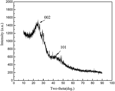
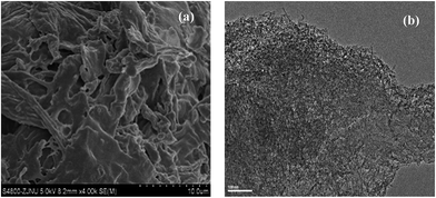
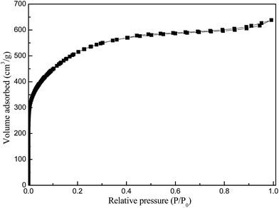
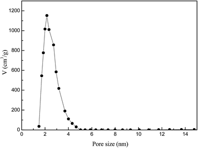
XRD profiles (Fig. 1) displayed only two broad peaks located at around 25 and 44° that were assigned to the carbon (002) and (101) diffractions, respectively.13 From the weak (002) peaks in the XRD profiles, the degree of graphitization could be low, revealing a low concentration of parallel single layers in the obtained carbon materials. The structure of as-synthesized carbon material is clearly shown in the SEM and TEM (Fig. 2(a) and (b)). From the TEM observations, apparent oriented multilayer domains and graphene sheets stacked in parallel were very few and not readily distinguishable, whereas mostly disordered graphene layer domains were observed in the sample, in agreement with the XRD analysis mentioned above. Their variational textures revealed that the structures of the resultant carbon materials could be tuned by reasonably changing the calcination temperature. It is proposed that the incomplete accumulation of FA inside the MOF-199 pores and the polymerization of FA as well as pyrolysis of polymerized FA (PFA) first produce small pores. Subsequently, the MOF-199 framework decomposes, behaving as both a carbon precursor and a template, which further affords the pore space of the resultant carbon materials during the high-temperature carbonization process. The general shape of the N2 sorption isotherms for FPC-1 (Fig. 3) suggests the existence of different pore sizes spanning from micro to mesopores. Especially, the steep increase in the adsorbed volume at low relative pressure reveals the presence of microporosity in the sample, and the following small slope observed at medium relative pressure as well as the desorption hysteresis denotes the existence of developed mesoporosity. The BET surface area is 1876 m2 g−1 and the total pore volume is 1.42 cm3 g−1. Pore size distribution of FPC-1 calculation by the BJH theory, is shown in Fig. 4. It is shown that FPC-1 is porous structure with pore-size distribution range from 1 to 5 nm.3.2 Adsorption isotherms
The analysis of the isotherm data by fitting them to different isotherm models is an necessary step to find the suitable model that can be used for design purposes. The Langmuir isotherm model assumes that a monolayer of adsorbed material (in liquid, such as DBT) is adsorbed over a uniform adsorbent surface (a flat surface of solid phase) at a constant temperature and that the distribution of the compound between the two phases is controlled by equilibrium constant. Thus, at equilibrium both rates of adsorption and desorption are equal. The linear form of Langmuir's isotherm model29 is presented by the following equation:
 | (2) |
Freundlich isotherm model30 is assuming that the adsorption process takes place on a heterogeneous surface. The Freundlich exponential equation is shown by the following equation:
 | (3) |
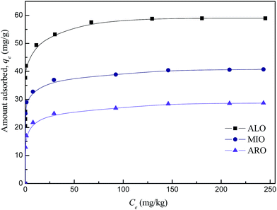
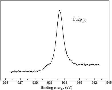
The equilibrium adsorption isotherms of DBT on the FPC-1 in ALO, ARO and MIO model oils were shown in Fig. 5. It exhibits a steep increase at low concentrations, indicating high affinity towards the DBT. At high DBT concentrations, the adsorbed amounts increase slightly, showing almost horizontal plateaus. The adsorption capacities of DBT on FPC-1 in this work are summarized in Table SI1,† together with those of the control adsorbents. It is clear that the adsorption capacity of FPC-1 is superior to some other previously reported adsorbents.31–36 There are possible two points for high uptake capacity of DBT onto the as-prepared porous carbon. Firstly, for this porous carbon, the surface area is 1876 m2 g−1 and the total pore volume is 1.42 cm3 g−1, which might increase the amount of accessible active sites and space for DBT. Secondly, according to Pearson's hard and soft acid–base concept, bases can be classified into two categories. One type of bases is polarizable and the other type is non-polarizable. These two groups are denoted as “soft” and “hard” bases, respectively. Similarly, acids can be classified based on their preferential interactions with hard or soft bases. Acids that form strong interactions with hard and soft bases are called hard and soft acids, respectively.37,38 According to this concept, sulfur-containing bases (e.g. DBT) are relatively intermediate to soft. Thus, soft DBT bases are strongly attracted to soft Lewis acids, such as Cu2+. The boiling point of Cu (about 2562 °C) is higher than the carbonization temperature (800 °C). Therefore, it might have some Cu2+ in the structure of the porous carbon, which significantly increased the sulfur capacity due to the acid–base interaction with DBT. In order to obtain the chemical state of Cu in the FPC-1, XPS analysis has been carried out (Fig. 6). As shown in Fig. 6, the Cu 2p3/2 spectrum shows shakeup peaks at around 944 eV, which is characteristic of Cu 2p3/22+ species.39 ICP analysis for FPC-1 showed that the content of copper was 24.3 wt%, which proved that copper existence in FPC-1 after the carbonization process.
The obtained experimental equilibrium adsorption data are then fitted using Langmuir and Freundlich isotherm models by eqn (2) and (3). The plot of Ce versus Ce/qe for Langmuir model of DBT on the FPC-1 was shown in Fig. SI1.† The calculated constants according to the three isotherm equations along with R2 values (standard deviation) are presented in Table SI2.† This table shows that the Langmuir isotherm gives the best fittings with R2 > 0.999. The good fittings to the Langmuir model for the DBT also suggest that the adsorption is limited with a monolayer coverage and the surface is relatively homogeneous.
For Langmuir isotherm, RL is used to show the essential character and it can be calculated using the following equation
 | (4) |
Fig. SI2† shown the plot of ln![[thin space (1/6-em)]](https://www.rsc.org/images/entities/char_2009.gif) qe versus ln
qe versus ln![[thin space (1/6-em)]](https://www.rsc.org/images/entities/char_2009.gif) Ce for the Freundlich isotherm. The plot yields a straight line with slope of 1/n, which indicated that the adsorption of DBT on the prepared porous carbon was favorable. Accordingly, Freundlich constants Kf, n and the correlation coefficients R2 were calculated from eqn (3) and listed in Table SI2.† As known from the results, the R2 values of Freundlich model are 0.9324, 0.988 and 0.995 for ALO, ARO and MIO, which is lower than that of Langmuir model. It proves that the Langmuir model could better describe the adsorption process.
Ce for the Freundlich isotherm. The plot yields a straight line with slope of 1/n, which indicated that the adsorption of DBT on the prepared porous carbon was favorable. Accordingly, Freundlich constants Kf, n and the correlation coefficients R2 were calculated from eqn (3) and listed in Table SI2.† As known from the results, the R2 values of Freundlich model are 0.9324, 0.988 and 0.995 for ALO, ARO and MIO, which is lower than that of Langmuir model. It proves that the Langmuir model could better describe the adsorption process.
3.3 Regeneration performance of FPC-1
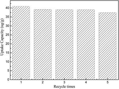
The adsorbents are required to be regenerative for multiple cycles to reduce the adsorbent cost. Generally, there are two techniques for regeneration of the adsorbent: the thermal treatment and the solvent elution. In this study, the solvent elution is adopted. The saturated FPC-1 was added to the glass bottles containing excess alcohol for 12 h at 25 °C. The sorbent was separated from the solution and washed by alcohol, the sulfur concentration of the filtrate solution was analyzed until it reached zero. After that, the FPC-1 was then dried at 120 °C for 24 h in a vacuum drying oven. As a representative procedure, the regenerated FPC-1 is tested in MIO model oil at 25 °C. Effects of the regeneration times are shown in Fig. 7. In comparison with fresh FPC-1, the adsorption capacity decreases by less than 5% at the second recycle time and then remains almost at the same level. Until the fifth regeneration, the adsorption capacity decreases by 8.5% but still remains at a high value. As a whole, the as-prepared adsorbents, i.e., FPC-1, can be easily regenerated after the adsorption desulfurization process and recycled five times at least.4. Conclusion
In conclusion, a new type of porous carbon material has been prepared using hydrothermal synthesis procedures from MOF-199 hard template. Characterization of this copper-containing porous material was confirmed by XRD, TEM, SEM, ICP, XPS and N2 adsorption. Its adsorption behaviors for DBT in three types of model oils are systematically investigated through batch adsorption tests. The as prepared FPC-1 has higher adsorption capacities for DBT from ALO, ARO and MIO model oils, even higher than some adsorbents reported in the literatures. Equilibrium data were best described by the Langmuir isotherm model. Owing to its textural characteristics, we believe that our FPC-1 material could be useful for various applications, such as catalytic supports, gas storage, biomolecule adsorption and drug delivery etc. Finally, the used MOF can be easily regenerated by solvent washing and reused at least five times.Acknowledgements
This work was supported by the Natural Science Foundation of Zhejiang Province of China (LY16B060002).References
- Y. Shi, X. Zhang, L. Wang and G. Liu, AIChE J., 2014, 60, 2747–2751 CrossRef CAS.
- A. Samokhvalov and B. J. Tatarchuk, Catal. Rev.: Sci. Eng., 2010, 52, 381–410 CAS.
- A. Stanislaus, A. Marafi and M. S. Rana, Catal. Today, 2010, 153, 1–68 CrossRef CAS.
- W. Dai, J. Hu, L. M. Zhou, S. Li, X. Hu and H. Huang, Energy Fuels, 2013, 27, 816–821 CrossRef CAS.
- P. Jeevanandam, K. J. Klabunde and S. H. Tetzle, Microporous Mesoporous Mater., 2005, 79, 101–110 CrossRef CAS.
- X. Gao, H. Mao, M. Lu, J. Yang and B. Li, Microporous Mesoporous Mater., 2012, 148, 25–33 CrossRef CAS.
- Y. Nie, C. Li and Z. Wang, Ind. Eng. Chem. Res., 2007, 46, 5108–5122 CrossRef CAS.
- A. Revelli, F. Mutelet and J. Jaubert, J. Phys. Chem. B, 2010, 114, 4600–4608 CrossRef CAS PubMed.
- Z. A. Irani, M. R. Mehrnia, F. Yazdian and M. Soheily, Bioresour. Technol., 2011, 102, 10585–10591 CrossRef CAS PubMed.
- D. P. Morales, A. S. Taylor and S. C. Farmer, Molecules, 2010, 15, 1265–1269 CrossRef CAS PubMed.
- S. Kumar, V. C. Srivastava and R. P. Badoni, Fuel Process. Technol., 2012, 93, 18–25 CrossRef CAS.
- Z. A. Irani, M. R. Mehrnia, F. Yazdian and M. Soheily, Bioresour. Technol., 2011, 102, 10585–10591 CrossRef CAS PubMed.
- B. Guo, R. Wang and Y. Li, Fuel, 2011, 90, 713–718 CrossRef CAS.
- R. T. Yang, A. J. Hernandez-Maldonado and F. H. Yang, Science, 2003, 301, 79–81 CrossRef CAS PubMed.
- X. L. Ma, S. Velu, J. H. Kim and C. S. Song, Appl. Catal., B, 2005, 56, 137–147 CrossRef CAS.
- E. Deliyanni, M. Seredych and T. J. Bandosz, Langmuir, 2009, 25, 9302–9312 CrossRef CAS PubMed.
- J. Bu, G. Loh, C. G. Gwie, S. Dewiyanti, M. Tasrif and A. Borgna, Chem. Eng. J., 2011, 166, 207–217 CrossRef CAS.
- L. Lin, Y. Zhang, H. Zhang and F. Lu, J. Colloid Interface Sci., 2011, 360, 753–759 CrossRef CAS PubMed.
- L. Huang, G. Wang, Z. Qin, M. Dong, M. Du, H. Ge, X. Li, Y. Zhao, J. Zhang, T. Hu and J. Wang, Appl. Catal., B, 2011, 106, 26–38 CAS.
- X. Tang, X. Meng and L. Shi, Ind. Eng. Chem. Res., 2011, 50, 7527–7533 CrossRef CAS.
- B. Van de Voorde, B. Bueken, J. Denayer and D. De Vos, Chem. Soc. Rev., 2014, 43, 5766–5788 RSC.
- S. Y. Jia, Y. F. Zhang, Y. Liu, F. X. Qin, H. T. Ren and S. H. Wu, J. Hazard. Mater., 2013, 262, 589–597 CrossRef CAS PubMed.
- K. A. Cychosz, A. G. Wong-Foy and A. J. Matzger, J. Am. Chem. Soc., 2008, 130, 6938–6939 CrossRef CAS PubMed.
- B. Liu, H. Shioyama, T. Akita and X. Qiang, J. Am. Chem. Soc., 2008, 130, 5390–5391 CrossRef CAS PubMed.
- Y. W. Shi, X. W. Zhang, W. Li and G. Z. Liu, AIChE J., 2014, 60, 2747–2751 CrossRef CAS.
- J. Hu, H. Yu, W. Dai, X. Yan, X. Hu and H. Huang, RSC Adv., 2014, 4, 35124–35130 RSC.
- H. L. Jiang, B. Liu, Y. Q. Lan, K. Kuratani, T. Akita, H. Shioyama, F. Zong and Q. Xu, J. Am. Chem. Soc., 2011, 133, 11854–11857 CrossRef CAS PubMed.
- C. G. Johan, A. A. P. Louk and P. R. Javier, Microporous Mesoporous Mater., 2003, 60, 1–17 CrossRef.
- I. Langmuir, J. Am. Chem. Soc., 1916, 38, 2221–2295 CrossRef CAS.
- H. M. F. Freundlich, Z. Phys. Chem., 1906, 57, 385–470 CAS.
- G. X. Yu, M. Jin, J. Sun, X. L. Zhou, L. F. Chen and J. A. Wang, Catal. Today, 2013, 212, 31–37 CrossRef CAS.
- W. L. Li, J. M. Xing, X. C. Xiong, J. X. Huang and H. Z. Liu, Ind. Eng. Chem. Res., 2006, 45, 2845–2849 CrossRef CAS.
- J. Wang, F. Xu, W. J. Xie, Z. J. Mei, Q. Z. Zhang, J. Cai and W. M. Cai, J. Hazard. Mater., 2009, 163, 538–543 CrossRef CAS PubMed.
- A. Srivastav and V. C. Srivastava, J. Hazard. Mater., 2009, 170, 1133–1140 CrossRef CAS PubMed.
- N. F. Nejad, E. Shams, M. K. Amini and J. C. Bennett, Microporous Mesoporous Mater., 2013, 168, 239–246 CrossRef.
- Y. Shi, X. Zhang, L. Wang and G. Liu, AIChE J., 2014, 60, 2747–2751 CrossRef CAS.
- I. Ahmed and S. H. Jhung, J. Hazard. Mater., 2016, 301, 259–276 CrossRef CAS PubMed.
- M. Maes, M. Trekels, M. Boulhout, S. Schouteden, F. Vermoortele, L. Alaerts, D. Heurtaux, Y. K. Seo, Y. K. Hwang, J. S. Chang, I. Beurroies, R. Denoyel, K. Temst, A. Vantomme, P. Horcajada, C. Serre and D. E. De Vos, Angew. Chem., Int. Ed., 2011, 50, 4210–4214 CrossRef CAS PubMed.
- J. H. Shan, X. Q. Liu, L. B. Sun and R. Cui, Energy Fuels, 2008, 22, 3955–4395 CrossRef CAS.
Footnote |
| † Electronic supplementary information (ESI) available. See DOI: 10.1039/c7ra02946b |
| This journal is © The Royal Society of Chemistry 2017 |

