
 Open Access Article
 This Open Access Article is licensed under a Creative Commons Attribution-Non Commercial 3.0 Unported Licence
Combined effects of hole doping and off-stoichiometry on the structures, transport, and magnetic properties of Sr(2−y)NayFe(1−x)Mo(1+x)O6 (x = 0/5x = y; y = 0, 0.05, 0.1, 0.15, 0.2, and 0.3)
Jin-Feng Wang * and
Yan-Ming Zhang
* and
Yan-Ming Zhang
College of Physics and Materials Science, Henan Normal University, Henan Key Laboratory of Photovoltaic Materials, Xinxiang 453007, China. E-mail: jfwang@htu.edu.cn
First published on 16th May 2017
Abstract
A series of double perovskite, Sr(2−y)NayFeMoO6 (y = 0, 0.05, 0.1, 0.15, 0.2, and 0.3) and Sr(2−y)NayFe(1−x)Mo(1+x)O6 (5x = y; y = 0.05, 0.1, 0.15, 0.2, and 0.3), ceramics were synthesized via a solid-state reaction. The influences of the doped Na (y) and off-stoichiometry (excess Mo: x) content on the structure, magnetization, chemical states, resistivity, magnetoresistance (MR), and the Curie temperature (TC) were systematically and comparatively investigated. The X-ray diffraction results indicated that the Fe/Mo ordering degree in Sr(2−y)NayFeMoO6 and Sr(2−y)NayFe(1−x)Mo(1+x)O6 exhibited a slight suppression for y = 0–0.15, whereas a significant decrease was observed for y = 0.2 and 0.3. X-ray photoelectron spectroscopy results confirmed that the chemical states of Fe and Mo cations in all the samples had +3 and +5 valences. With the decreasing y values, it was observed that the saturated magnetization Ms demonstrated a gradual decrease, in good agreement with the suppression of the Fe/Mo ordering degree. This close correlation between the magnetic properties and the Fe/Mo ordering degree indicates that the magnetic behaviors are predominantly controlled by the ordering degree of Fe/Mo in all the ceramics. The MR behavior in the samples is mainly determined by the grain boundary conditions. Upon comparing Sr(2−y)NayFeMoO6 with Sr(2−y)NayFe(1−x)Mo(1+x)O6 (5x = y) for the same y value, Sr(2−y)NayFe(1−x)Mo(1+x)O6 (5x = y) showed a decreased grain boundary strength (the resistivity); thus, a diminished MR performance was observed, indicating that introducing excess Mo into the hole-doped Sr2FeMoO6 system was disadvantageous for practical applications. Interestingly, the TC of both Sr(2−y)NayFeMoO6 and Sr(2−y)NayFe(1−x)Mo(1+x)O6 (5x = y) gradually decreased until y = 0.15, but improved on further increasing the y value. This composition-dependent tendency of TC cannot be explained only on the basis of the itinerant electron density, which is responsible for the optimized TC in the electron-doped Sr2FeMoO6 systems.
I. Introduction
The double perovskite Sr2FeMoO6 (SFMO) material with the formula A2B′B′′O6 has been extensively investigated because it exhibits a rich variety of physical properties including a half-metal property with 100% spin-polarization in the ground state, considerable low-field magnetoresistance (MR) behavior at room temperature, and a high Curie temperature (TC) of ca. 415 K.1–7 Therefore, SFMO has attracted significant attention from the point of view of fundamental investigations and potential applications in spintronics and magnetoresistive devices at room temperature.4,6,8The electronic configuration of SFMO can be simply described as 3d5 (Fe3+) and 4d1 (Mo5+). The spin-up electrons of Fe-3d5 (t32g and e2g) are localized and fully occupy the Fe-3d orbitals, whereas the spin-down electron contributed by Mo-4d1 is itinerant and partially occupies the t2g orbits formed by the hybridized Fe-3d and Mo-4d with O-2p orbitals. Localized electrons of Fe3+ (3d5, S = 5/2) antiferromagnetically couple with the itinerant electron of Mo5+ (4d1, S = 1/2), resulting in a net magnetization of 4μB/f.u.1,4,9–13 However, it is commonly found that a much lesser magnetization than 4μB/f.u. is reported in the experiments because of the existence of the ubiquitous Fe/Mo anti-site defects, which are caused by the misplacement of Fe in the Mo positions and vice versa. The itinerant electron of Mo5+ plays an important role in the stabilization of the ferromagnetic states via a double-exchange-like model.9,11,14,15 The carrier density at the Fermi level has been proposed to have a close correlation with the TC of the double perovskite.15–21 Actually, the ferromagnetic TC of A2FeMoO6 (A: Ca/Ba/Sr) can indeed be significantly enhanced by substituting the divalent A2+ ions with the trivalent ions (such as La3+, Nd3+, Sm3+ etc.).15,17,19,22–27 A substantial increase in the ferromagnetic TC is because of the increase in the carrier density caused by electron injection into the conduction band. However, recent investigation has shown that the ferromagnetic state of LaxSr2−xFeMoO6 becomes unstable, and the TC will decrease when too many electrons are doped in the conduction band (x > 1).28–30 These are representative examples displaying a strong dependence of the physical property on the carrier number in A2FeMoO6 (A: Ca/Ba/Sr) systems. Except for the TC, other physical properties, such as the chemical states of Fe and Mo ions, magnetization, resistivity behavior, and the MR performance, are greatly influenced by the carrier density as well.15,17,19,21,23,28,31–34 Hence, the concept of carrier density at the Fermi level is important for understanding and manipulating the physical properties in SFMO. To understand the effect of carrier density on the physical properties of SFMO, it is important to artificially control the carrier density in SFMO ceramics using an experimental strategy. However, it is actually difficult to control the carrier density over a wide range in single-phased SFMO although according to the literature, some SFMO ceramics with different carrier densities have been prepared.21,31,33,34
Experimentally, there are mainly three methods to modify the carrier density and further probe the corresponding physical properties of SFMO: the first method is to completely substitute Fe or Mo with other elements; the second method is carrier doping that is achieved by partially replacing Sr2+ with trivalent ions (such as La3+, Nd3+, Sm3+ etc.) or univalent ions (such as K+ and Na+);15,19,26,33,35 and the third method is to tune the ratio of Fe/Mo.31,36 Among the above mentioned three methods, although the first method is beneficial for exploring new double perovskites, it will destroy the intrinsic physical properties to some extent: for example, the ferromagnetic behavior and half-metal property in Sr2FeWO6 will disappear,37 the TC of Sr2FeOsO6 will have a low value of ca. 65 K, and so on.38,39 As is well-known, carrier doping in A2FeMoO6 (A: Ca/Ba/Sr) systems has been proposed to be an effective way for tuning the carrier density in the conduction band and further probe the ferromagnetic coupling strength. Studies on hole-doped SFMO are relatively less than those on electron-doped ceramics, and there is still some controversy on the impact of the reduction in the carrier density caused by hole doping on the magnetization and TC. Zhang et al. claimed that the contribution of the hole band-filling effect to an optimized magnetization in Sr2−xNaxFeMoO6 (0 < x ≤ 0.17) cannot be ignored, and the improved TC was attributed to the change in the relative carrier density of the Fe and Mo cations caused by Na doping.34 Contrary to the abovementioned phenomena, both the decreased magnetization and TC can be found in other similar hole-doped A2FeMoO6 (A = Sr and K) systems, originating from the Fe/Mo disorder and lower carrier density, respectively.35,40 Compared to the former two methods, only a few studies on SFMO with excess Fe content can be found, which mainly aim at the understanding of the relationship of the Fe and Mo sites with magnetization;31,36,41 however, investigations on the carrier density are scarce. Recently, theoretical predications have revealed that improved TC can be obtained in LaxSr2−xFe1+yMo1−yO6 (x = 3y) without sacrificing polarization, which is attributed to the compensation of electron doping (La3+) for the reduction in the carrier density in Sr2Fe1+yMo1−yO6.42 Based on this prediction, it might be an effective strategy to tune the carrier density by combining the A-site carrier doping with B-site off-stoichiometry in SFMO. Additionally, hole doping in SFMO will certainly reduce the carrier density, and the itinerant electron is contributed by Mo5+. Theoretically, introducing excess Mo into hole-doped SFMO may progressively compensate for the decrease in the carrier density. Then, the physical properties will be accordingly tuned. Similar studies on these systems are relatively rare; thus, it is interesting and meaningful to conduct further these studies on these systems.
In this study, the single-phased pristine SFMO and Na-hole-doped Sr(2−y)NayFeMoO6 (y = 0.05, 0.1, 0.15, 0.2, and 0.3) ceramics were prepared. For comparison, pure Sr(2−y)NayFe(1−x)Mo(1+x)O6 with an excess Mo content for the same y values (y = 5x; y = 0.05, 0.1, 0.15, 0.2, and 0.3) were also synthesized. The combined effects of hole-doping and off-stoichiometry on the carrier density and the corresponding crystal structure, magnetization, resistivity, magnetoresistance, and the TC were systematically and comparatively investigated.
II. Experimental
For simplicity and clarity, the Sr(2−y)NayFeMoO6 (y = 0, 0.05, 0.1, 0.15, 0.2, and 0.3) ceramics were labeled as C0, C1, C3, C5, C7, and C9, respectively, in which C0 was a pristine SFMO and C1–C9 were hole-doped compositions. To compare the influence of the excess Mo on the hole-doped C1–C9, for each composition with the same y values, a certain excess Mo content (y = 5x) was designed, and the Sr(2−y)NayFe(1−x)Mo(1+x)O6 (y = 5x; y = 0.05, 0.1, 0.15, 0.2, and 0.3) ceramics were denoted as C2, C4, C6, C8, and C10, respectively. Each group of (C1, C2), (C3, C4), (C5, C6), (C7, C8), and (C9, C10) has the same y value. The abovementioned compositions were prepared by the solid-state reaction process. First, all the raw materials SrCO3, Na2CO3, Fe2O3, and MoO3 (≥99.5%) were dried and weighed according to the designed chemical formulas, mixed by ball milling in ethanol for 24 hours, and dried in air at 80–90 °C. The dried mixtures were calcined at 800 °C for 10 hours in air. Then, the calcined powders were ball milled in ethanol again for another 24 hours, and the slurry was dried and pressed into small thin pellets (10 × 1 mm). Finally, the pellets were sintered at 1200 °C for 15 hours in a reducing atmosphere of a mixed gas of 5% H2/95% Ar.The structure of the compositions was confirmed by X-ray diffraction (XRD) patterns (XRD, Bruker D8 Discover). The chemical states of the Fe and Mo cations were investigated by X-ray photoelectron spectroscopy (XPS, Thermo Scientific K-Alpha). The magnetic and transport data were obtained using a physical property measurements system (PPMS Quantum Design, 2001NUGC).
III. Results and discussions
Fig. 1(a) shows the normalized XRD patterns for all the samples. It can be clearly seen that all the diffraction peaks are in accordance with double perovskite structure with a tetragonal phase and a space group of I4/m,1,10,37 and no other impurities are detected. This implies that the C0–C10 compositions are single-phased. The superstructure diffracted peak of (101) plane located at ca. 19.8° results from the ordered arrangement of Fe and Mo cations at the B-sites (Fig. 1(a) and (b)). The (101) peak intensity progressively decreases entirely from C0 to C10, whereas still persists in C10. Additionally, the peak intensity of the (101) plane has a close relationship with the Fe/Mo ordering degree, and it has been well accepted that the relative intensity of I(101)/{I(200) + I(112)} is a ordering degree parameter defined by Balcells et al.,43 which can qualitatively reflect the Fe/Mo ordering degree content. The variance of I(101)/{I(200) + I(112)} as a function of the Na content (y) is plotted in the inset in Fig. 1(a), from which, mainly three phenomena can be observed. The first phenomenon is that the relative intensity of I(101)/{I(200) + I(112)} in C0, C1, and C2 is comparable, indicating that the Fe/Mo ordering degree in C1 and C2 is almost the same. The second phenomenon is that the relative intensity of I(101)/{I(200) + I(112)} overall decreases with the increasing y values for either C0–C9 (the black line) or C2–C10 (the red line). Similar results have been reported for Sr2−xKxFeMoO6.35,40 However, these are contrary to the results obtained for the Na-doped SFMO,34 in which an enhanced Fe/Mo ordering degree can be obtained, arising from the selective injection of the doped holes into the conduction band. Additionally, the phenomenon, as shown in the inset in Fig. 1(a), is also not consistent with the Ba2−xNaxFeMoO6 (x = 0–0.6) system,33 indicating that the ordering degree of Fe/Mo has no obvious correlation with the Na doping level. The third phenomenon is that the relative intensity of I(101)/{I(200) + I(112)} of the excess Mo ceramics show a slight suppression for the same y values (y = 0.05, 0.1, and 0.15), such as in C3 and C4; this suppression will be obvious when y is 0.2 and 0.3, as indicated in C9 and C10. Substituting the regular Fe sites with the excess Mo cations tends to bring about extra intrinsic Fe/Mo anti-site defects.44 Hence, the decrease in the relative density of I(101)/{I(200) + I(112)} is reasonable.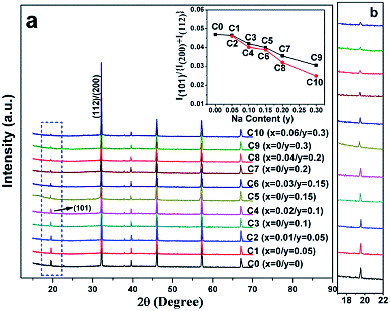 | ||
| Fig. 1 (a) XRD patterns of C0–C10, the inset in (a) is the ratio of the I(101)/{I(200) + I(112)} as a function of the Na content (y); (b) the locally enlarged XRD patterns. | ||
The chemical states of Fe and Mo cations will influence the band structure and thus affect the magnetic behaviors and other physical properties. Therefore, the chemical states of Fe and Mo cations were characterized via XPS, and the XPS spectra of Fe-2p and Mo-3d for all the samples are shown in Fig. 2(a) and (b), respectively. From Fig. 2(a), it can be clearly seen that Fe 2p3/2 and Fe 2p1/2 of the C0–C10 ceramics are located at ca. 710.5 eV and 724.5 eV, respectively, with a spin-energy separation of 14 eV, which indicates that the Fe cations in C0–C10 are mainly in +3 oxidation state.45,46 The double peaks contributed by Mo 3d5/3 and Mo 3d2/3 due to spin–orbit coupling can be observed in Fig. 2(b). Except for these, there are no other shoulder peaks, which is different from the XPS data of SFMO systems reported in literature.45,47 The location of the binding energy of the Mo 3d5/3 and Mo 3d2/3 peaks shows a weak shift, over the range of 232.2–231.5 eV and 234.8–235.4 eV, respectively. Actually, all the Mo 3d XPS experimental data are in accordance with the reported data, and it demonstrates that the chemical state of the Mo cations of C0–C10 is +5 valence.47–49 Based on the XPS results, it can be concluded that Na-doped and Fe/Mo off-stoichiometry play a negligible role in the chemical states of Fe and Mo cations.
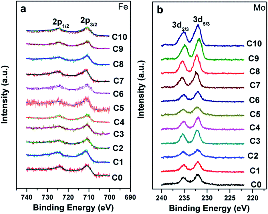 | ||
| Fig. 2 X-ray photoelectron spectra of the Fe cation (a) and Mo cation (b) in C0–C10. | ||
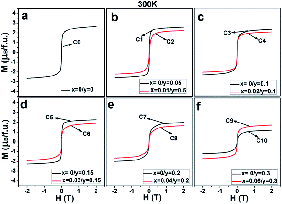
Magnetization curves as a function of the external field (M–H) measured at 50 K for all the ceramics are shown in Fig. 3(a–f). It can be clearly seen that all the ceramics show well-saturated hysteresis loops with a small coercive field, indicating a soft ferromagnetic behavior. The saturated magnetization Ms values gradually decrease with the increasing Na doping level (y) and decrease further on introducing excess Mo (5x = y) for a certain y value. This implies that both Na hole doping and excess Mo content negatively affect the Ms values. The original causes for the observations are unclear, and it is necessary to fundamentally estimate and discuss their roles.
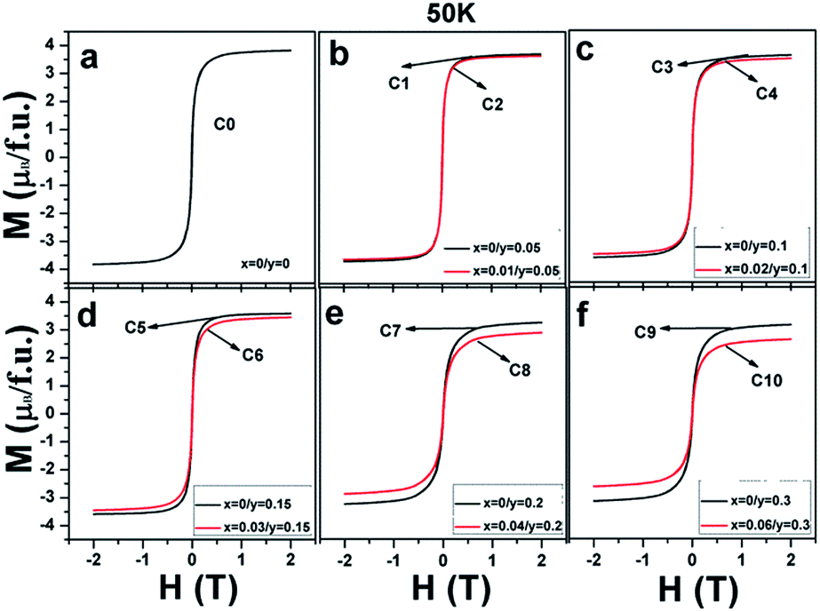 | ||
| Fig. 3 Magnetic hysteresis loops at 50 K for (a) C0; (b) C1, C2; (c) C3, C4; (d) C5, C6; (e) C7, C8; and (f) C9, C10. | ||
Before investigating the effects of Na (y) and excess Mo (x) content on the Ms values, it is important to fundamentally understand what contributes to the magnetization in the SFMO system. At present, mainly two alternative explanations for the magnetization in the SFMO system have been proposed. In the first explanation, the Fe/Mo anti-site defect (contrary to the Fe/Mo ordering degree), caused by the incorrect occupancy of Fe at the Mo site or vice versa, mainly negatively affects the magnetization behavior in SFMO. The reasons are because Fe3+ (3d5, S = 5/2) ions in the ideal crystal structure of SFMO ferromagnetically interact with each other, but antiferromagnetically couple with Mo5+(4d1, S = 1/2) in the itinerant Fe(t2g)–O–Mo(t2g) sub-band; hence, a macroscopic ideal saturated magnetization of 4μB/f.u. is presumed. However, the Fe/Mo anti-site defect can result in antiferromagnetic coupling of the Fe–O–Fe–O and paramagnetic Mo–O–Mo–O patches between magnetic domains in a single grain. Therefore, it is obvious that both patches can significantly reduce the magnetization values;9,43,50 in the other explanation, the itinerant electron density n at spin-down Fe(t2g)–O–Mo(t2g) sub-band is suggested to have a positive correlation with the magnetization.34 Because localized electrons of Fe3+ (3d5, S = 5/2) antiferromagnetically interact with the itinerant electron of Mo5+ (4d1, S = 1/2), they lead to an ideal magnetization of 4μB/f.u. The theoretical magnetization value will be more than 4μB/f.u. if n is less than 1; otherwise, it will be less than 4μB/f.u. To investigate the effects of Na content (y) and excess Mo content (x) on the evolution of n, the dependencies of n on the y and x values for all the ceramics are demonstrated in Table 1. Herein, the ideal Ms(c) labeled in the table was calculated for the SFMO system with 100% Fe/Mo ordering degree.
| Sample I | C0 | C1 | C3 | C5 | C7 | C9 |
| n | 1 | 0.95 | 0.9 | 0.85 | 0.8 | 0.7 |
| Ms(c) (μB/f.u.) | 4 | 4.05 | 4.1 | 4.15 | 4.2 | 4.3 |
| Sample II | C0 | C2 | C4 | C6 | C8 | C10 |
| n | 1 | 0.98 | 0.96 | 0.94 | 0.92 | 0.88 |
| Ms(c) (μB/f.u.) | 4 | 4.02 | 4.04 | 4.06 | 4.08 | 4.12 |
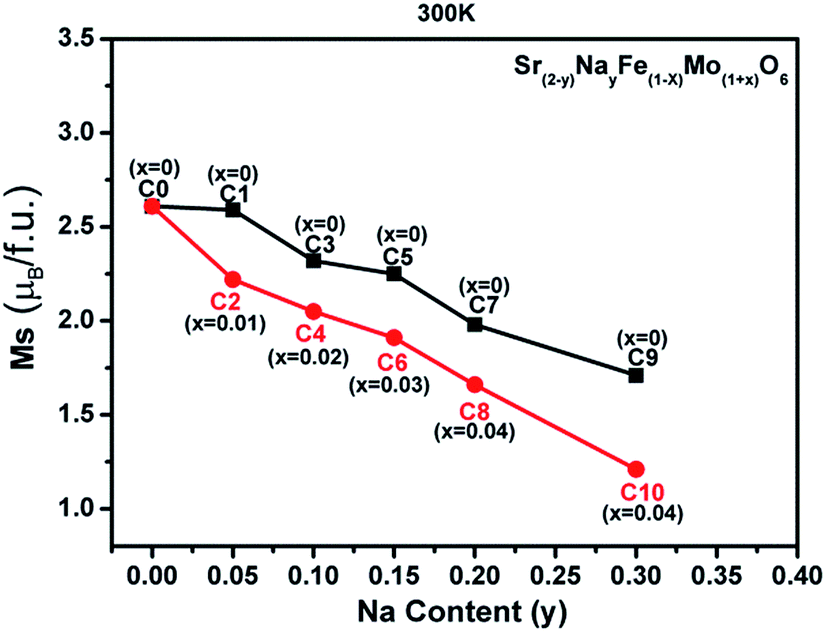
The evolutions of both the Fe/Mo ordering degree (Fig. 1) and itinerant electron density (n) (Table 1) as a function of the x and y values were investigated as abovementioned. Moreover, changes in the experimentally saturated magnetization (Ms) for all the ceramics, as shown in Fig. 4, have been discussed hereinafter. From this, two aspects of Ms with y values can be expressed. In the first aspect, with the increasing Na content (y), the Ms values show a slow suppression, but an abrupt decrease when y ≥ 0.2 for both C0–C9 (the black curve) and C2–C10 (the red curve); in the other aspect, the Ms values of the ceramics C2, C4, and C6 are slightly lower than those of C1, C3, and C5, respectively, when y ≤ 0.15, and this gap significantly widens for y ≥ 0.2: for instance, in C7 and C8. From the inset in Fig. 1(a), it can be concluded that the Fe/Mo ordering degree content of the C0, C1, and C2 ceramics are almost the same. If the Ms is mainly controlled by the itinerant electron, the slightly higher Ms values in C1 and C2 than that in C0 should be observed, as shown in Fig. 4. However, this supposition is contrary to the experimental results shown in Fig. 4. It reveals that the magnetization behavior in a SFMO system is not predominantly contributed by the itinerant electron density at the Fermi level. There is some discrepancy in the claims in the Sr2−xNaxFeMoO6 and Ba2−xNaxFeMoO6 systems.33,34 Actually, the varying tendency of Ms with the Na content (y) is in accordance with that of the Fe/Mo ordering degree (inset in Fig. 1(a)), and this indicates that the magnetization property is mainly controlled by the Fe/Mo ordering degree. Similar views have been proposed in the K hole-doped SFMO and Ba2FeMoO6 systems.35,40
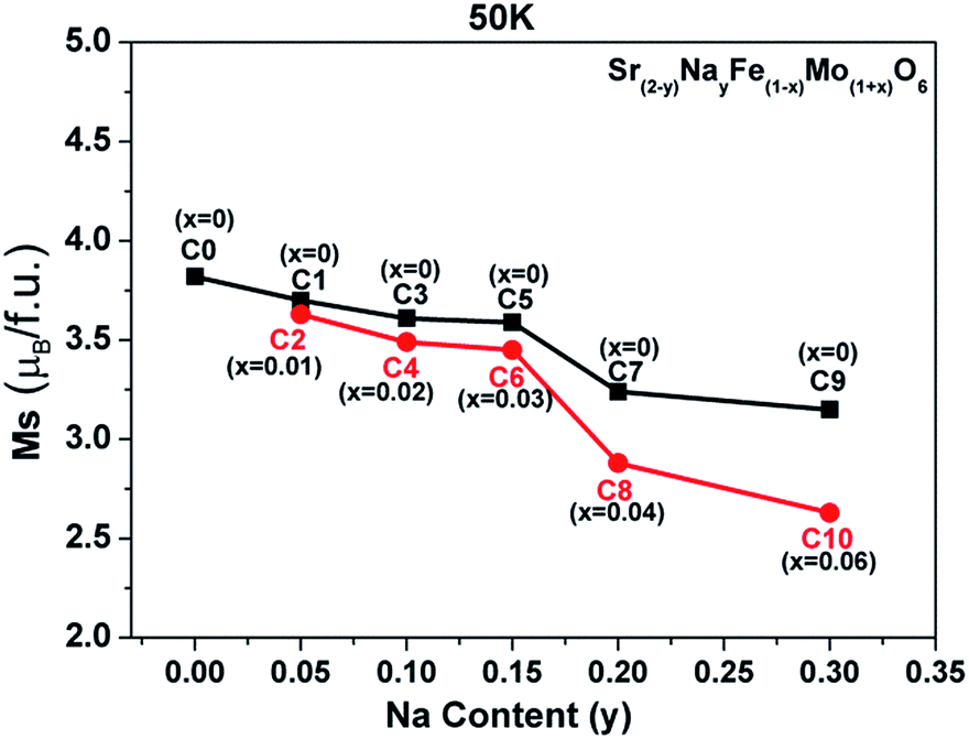 | ||
| Fig. 4 The saturated magnetization (Ms) curves as a function of the Na content (y) for all the samples. | ||
Now, the dominant contribution of the Fe/Mo ordering degree to the Ms values has been established. It is possible to further probe the magnetization process for all the ceramics with different Fe/Mo ordering degrees, originating from various Na contents (y) and excess Mo content (x). To realize this aim, (M/Ms)2 vs. H curves are plotted in Fig. 5(a) for sample I, Fig. 5(b) for sample II, as mentioned in Table 1, and Fig. 5(c) for C5, C6, C7, and C8. As observed in Fig. 5(a), the C0–C9 ceramics exhibited a rapid increase in magnetization within ca. 0.12 T, relatively smoothly between ca. 0.12 T and 1.5 T, and a saturated state at 2 T. However, a much smoother improvement of magnetization for C7 and C9 than that of other ceramics was observed over the magnetic field range of ca. 0.12–1.5 T, indicating that the magnetization process in C7 and C9 was more difficult compared to that in other ceramics. This magnetic hardening phenomenon was due to the abruptly reduced Fe/Mo ordering degree in C7 and C9.43,50 As shown in Fig. 1, the Fe/Mo anti-site defect has a close correlation with the Na content (y), and it significantly increases in C7 and C9 when y ≥ 0.2. Consequently, the magnetic domains are more tightly held in C7 and C9 with more Fe/Mo anti-site defect content, and then, the magnetic domain rotation process will become more difficult with the application of the external field.50 In other words, it becomes increasingly difficult to saturate the samples with more Fe/Mo anti-site defects. Therefore, the results shown in Fig. 5(a) are reasonable. The observations shown in Fig. 5(b) and (c) can be well understood and explained in the same way from the viewpoints of the Fe/Mo anti-site defect (ordering degree). The correlations of the Na content (y) and excess Mo content (x) with the magnetic behavior of all the samples at 50 K were comparatively and systematically investigated, as shown in Fig. 3–5. Actually, the magnetic properties at 300 K for all the samples demonstrated a similar dependence, as shown in Fig. 6–8.
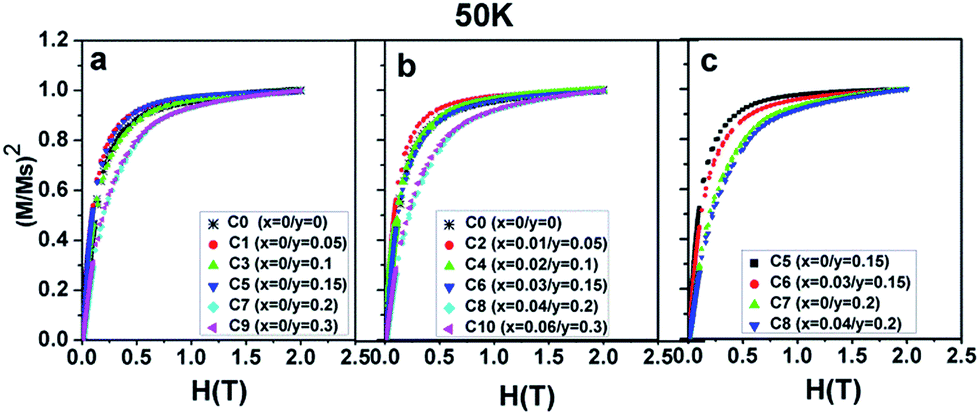 | ||
| Fig. 5 (M/Ms)2 curves as a function of the magnetic field (H) for (a) C0, C1, C3, C5, C7, C9; (b) C0, C2, C4, C6, C8, C10; (c) C5, C6, C7, C8. | ||
 | ||
| Fig. 6 Magnetic hysteresis loops at 300 K for (a) C0; (b) C1, C2; (c) C3, C4; (d) C5, C6; (e) C7, C8; and (f) C9, C10. | ||
 | ||
| Fig. 7 The room-temperature saturated magnetization (Ms) vs. the Na content (y) curves for all the samples. | ||
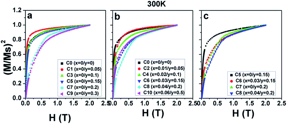 | ||
| Fig. 8 (M/Ms)2 as a function of the magnetic field H at 300 K for (a) C0, C1, C3, C5, C7, and C9; (b) C0, C2, C4, C6, C8, and C10; and (c) C5, C6, C7, and C8. | ||
To comparatively investigate the effect of the Na content (y) and the excess Mo content (x) on the electrical transport property, all the samples were artificially divided into six groups, C0 (y = 0); C1, C2 (y = 0.05); C3, C4 (y = 0.1); C5, C6 (y = 0.15); C7, C8 (y = 0.2); and (C9, C10, y = 0.3), based on different y values, and the corresponding zero-field resistivity against the temperature curves is plotted in Fig. 9(a–f), respectively. Herein, two interesting phenomena can be observed from Fig. 9. The first is that the electrical transport property of C0–C10 is sensitive to the Na doping level, judging from the overall resistivity variance. Low Na-doped C1, C2, and pristine C0 exhibit a semiconductor behavior over the measured temperature range; moderate Na-doped C3 and C4 show a metal-like behavior until ca. 120 K and then an insulator-like behavior on further decreasing the temperature; high Na-doped C5–C10 demonstrate a metal-like behavior over the entire temperature region. The observations indicate a sensitivity of the transport property towards the Na doping level. This is consistent with the Na-doped Ba2FeMoO6, in which the resistivity behavior is also sensitive to the Na doping level.33 However, the observation shown in Fig. 9 was found to be completely different from that reported for La-doped SFMO system in our previous works, in which the resistivity had no obvious correlations with the La doping level.51 The second is that for each group with the same y value, when excess Mo is introduced into the Na-doped ceramics, the resistivity values tend to diminish. For example, the value of C6 is lower that of C5 over the entire temperature range. Evolutions of the primary resistivity values were neither investigated in the hole-doped SFMO system nor in the combined hole-doped with an excess Mo content SFMO system. Actually, the resistivity values in the ceramics predominantly relate to the microstructures of the bulk, which mainly refers to the conditions of the grain boundaries. These conditions mainly include the sizes, connectivity and numbers of grains, structural defects, and local states density, which are experimentally related.4,52,53 It has been suggested that the conditions of the grain boundary (grain strengthening) can be expressed by the microscopic resistivity values.52,53 Based on this viewpoint, the phenomena shown in Fig. 9 ensures that Na hole-doping gradually suppresses the grain boundary strengthening in the SFMO system, and the excess Mo content further reduces the grain boundary strengthening in the Na-doped SFMO system.
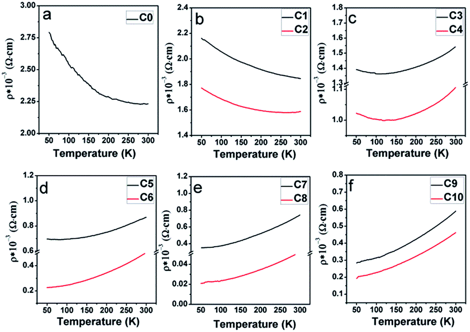 | ||
| Fig. 9 Resistivity–temperature curves with zero magnetic field for (a) pristine C0; (b) C1, C2; (c) C3, C4; (d) C5, C6; (e) C7, C8; and (f) C9, C10. | ||
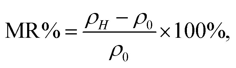
Similar to the resistivity–temperature curves, the samples (C0, C1, C2), (C3, C4), (C5, C6), (C7, C8), and (C9, C10) were divided into five groups, and the respective MR–H curves measured at 50 K are presented in Fig. 10(a–e). The MR% is defined as follows:
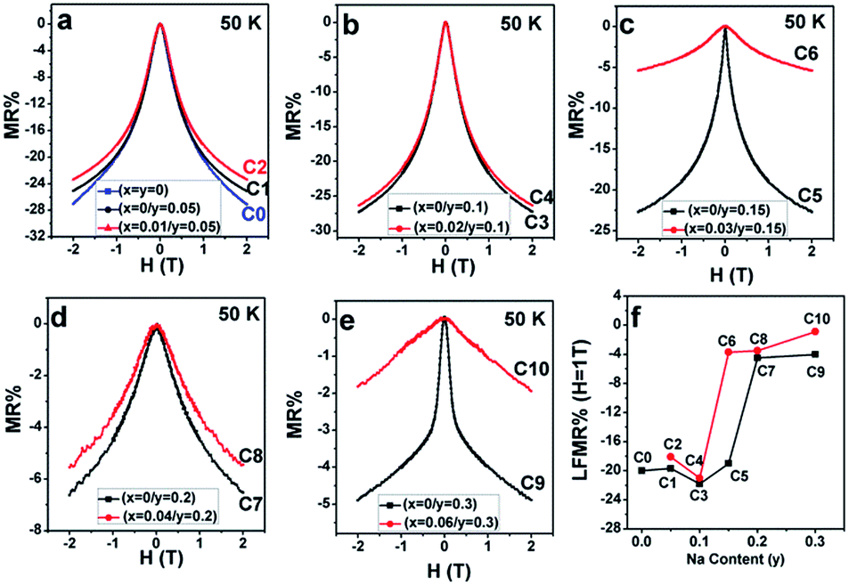 | ||
| Fig. 10 Magnetoresistance as a function of the magnetic field (MR–H) curves at 50 K for (a) C0–C2; (b) C3, C4; (c) C5, C6; (d) C7, C8; and (e) C9, C10. (f) Variances of the MR% at 1 T with the Na content (y). | ||
From Fig. 10(a–e), mainly three observations can be drawn: the first is that except for C10, the other ceramics exhibit a typical characteristic of low-field magnetoresistance (LFMR) that the negative MR steeply increases at a low-field (H ≤ 1 T), but relatively smoothly increases at high field (H > 1 T);4,5,53,54 the second is that the behavior and values of MR–H in the five C0–C5 samples are comparable; the third is that with the increasing Na content (y), an overall decreasing trend of MR is observed in SFMO (C1, C3, C5, C7, and C9), and an abrupt suppression is found in C7 (y = 0.2) and C8 (y = 0.3). However, upon introducing excess Mo in the Na-doped SFMO system with a given y value, the MR property further diminishes, especially for C6 and C10. Actually, dependencies of the MR behavior on the Na content (y) at 300 K are similar to those at 50 K (Fig. 11). As is well-known, the LFMR behavior in SFMO is a key functional characteristic from the viewpoint of practical applications. Therefore, the LFMR (H = 1 T) against Na content (y) is shown in Fig. 10(f). A comparable LFMR response was found in the ceramics when y ≤ 0.1, and a decreased LFMR behavior was observed for y > 0.1. Moreover, the Na-doped ceramics with excess Mo content (the red broken line) demonstrates a lower LFMR than the only Na-doped (the black broken line) ceramics. These observations are in good agreement with the resistivity trend (grain boundary strengthening), as shown in Fig. 9. Previous experimental data have confirmed that both the SFMO single crystals and epitaxial thins films show a minimal MR behavior;55,56 however, an appreciable MR response is observed in the SFMO polycrystals.1,4,5,52,53 This sharp contrast indicates that the LFMR in SFMO ceramics is a tunneling-type MR arising from spin-dependent carriers occurring at the grain boundaries. Hence, the grain boundary has a positive contribution to the MR response. Actually, the conditions of the grain boundary (grain boundary strengthening) predominantly control the LFMR behavior in the SFMO ceramics. As was expected, the LFMR can be significantly optimized by modifying the conditions of the grain boundary such as reducing the sizes of the grains, slightly oxidizing the grain boundary, and introducing the insulator or semiconductor into the grain boundary.5,52,53,57–60 The experimental results show that the remarkable optimized LFMR response originates from an enhancement in the grain boundary strengthening, which can be expressed by the macroscopic resistivity values.52,53,59,60 Based on the results shown in Fig. 9, the grain boundary strengthening of the ceramics C0, C1, C2, C3, and C4 was comparable as they had similar resistivity values. Additionally, via a comparison between the red lines (C2, C4, C6, C8, C10) and the black lines (C1, C3, C5, C7, C9), it was observed that introduction of excess Mo into the Na-doped ceramics (C2, C4, C6, C8, and C10) can bring about a decreased grain boundary strengthening. Therefore, the observations shown in the Fig. 10 are reasonable. However, this reduced MR performance in the SFMO system is detrimental to the practical applications in magnetic storage devices.
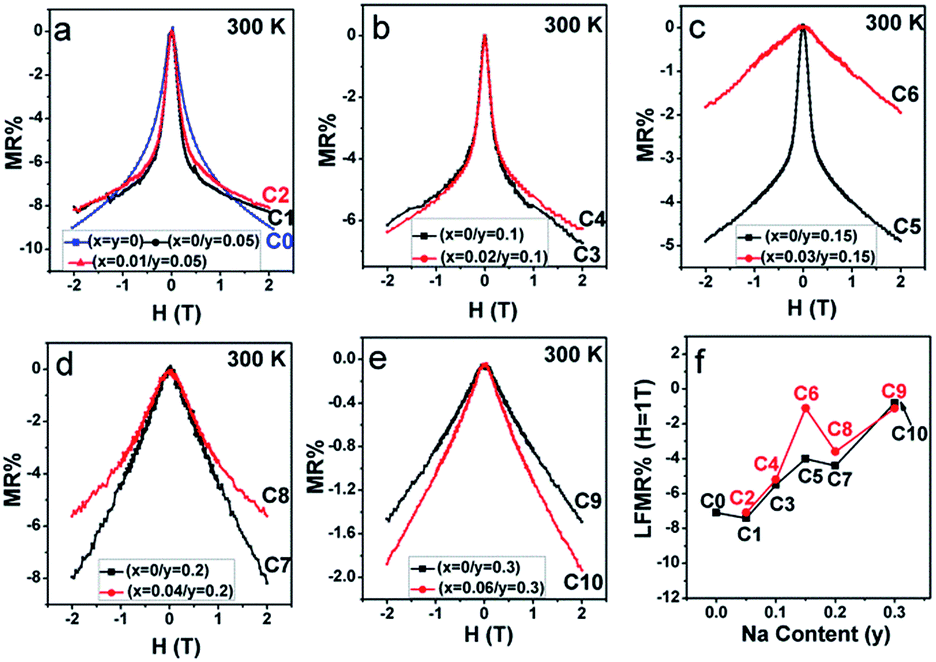 | ||
| Fig. 11 MR–H curves of (a) C0–C2; (b) C3, C4; (c) C5, C6; (d) C7, C8; and (e) C9, C10 at 300 K. (f) LFMR% at 1 T for C0–C10 as a function of the Na content (y). | ||
The field-cooling (200 Oe) magnetization as a function of temperature (M–T) for different samples is shown in Fig. 12(a–e). On decreasing the temperature, all the ceramics transited from a paramagnetic state to a ferromagnetic state. Moreover, the ferromagnetic TC, manifested by an abrupt drop in the magnetization to zero, can be estimated from the inflection point of the M–T curves.15 The doped Na (y)-dependent TC curves are plotted in Fig. 12(f), from which, it can be found that the excess Mo-doped samples (the red broken lines) show a higher TC than the only Na-doped samples (the black broken lines) for y ≤ 0.15, whereas a lower TC value is observed when y > 0.15. The correlations of TC with the doped Na (y) in C0–C10 are somewhat different from those of magnetization (Fig. 3–8), resistivity (Fig. 9), and MR (Fig. 10 and 11) responses as abovementioned. Moreover, the TC variance is not monotonously dependent on the y value for both the Mo-doped (the red broken line) and the Na-doped ceramics (the black broken line), and the TC values decrease with the increasing y values, reaching a minimum and then increasing with the further increase in the y content. Similar results have been reported for Sr2−xNaxFeMoO6 and La1−xCaxMnO3.34,61 Strong ferromagnetic interactions in all the ceramics are noticeable, as indicated by the TC values that are well above the room temperature. This strong magnetic interaction is mediated by the itinerant electron at the conduction band through a double-exchange-like mechanism, and it is proposed that the TC value in SFMO has a close correlation with the itinerant electron density at the Fermi level.15 The TC value is indeed significantly improved by electron doping because of the band filling effect.17,23 Based on these investigations, it is important to examine the itinerant electron density (n). The itinerant electron density (n) of the Na-doped C1–C9 (Sr2−yNayFeMoO6) and Mo-doped C2–C10 (Sr2−yNayFe(1−x)Mo(1+x)O6) can be simply expressed as (n(Na) = 1 − y) and (n(Mo) = 1 − y + 3x) per formula unit, respectively. Theoretically, both n(Na) and n(Mo) will decrease with the increasing y values, and the n(Mo) is always larger than n(Na), as shown in Table 1. The TC behavior in samples (y ≤ 0.15) can be qualitatively well explained. Moreover, the itinerant electron density is positively dependent on TC and this has been confirmed in electron-doped SFMO.15,17,21,22,24 However, the TC response in ceramics (y > 0.15) does not exhibit a tendency as expected. This indicates that the TC behavior may be determined by other contributions when the carrier density is very low. For example, the contribution to the total carrier density at the Fermi level by the Fe (n(F)) and Mo (n(M)) cations will be changed when y > 0.15, where TC has a positive correlation with n(M), but has a negative correlation with n(F). Perhaps, when y > 0.15, the n(M) decreases slower than n(F) in C7–C10; hence, an increased TC is observed despite the decrease in the total carrier density. However, the n(M)/n(F) ratios in Na-doped C7 and C9 are slightly higher than those in the Mo-doped C8 and C10, leading to a larger TC in C7 and C9. Actually, this comprehensive effect of the combined hole-doped and off-stoichiometric ratio on the TC behavior requires to be further probed.
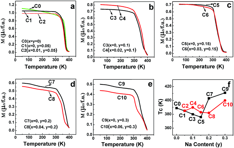 | ||
| Fig. 12 Magnetization curves as a function of temperature for (a) C0–C2; (b) C3, C4; (c) C5, C6; (d) C7, C8; and (e) C9, C10. (f) Evolution of the Curie temperature (TC) as a function of the doped Na (y). | ||
IV. Conclusions
Single-phase Sr(2−y)NayFeMoO6 (y = 0, 0.05, 0.1, 0.15, 0.2, and 0.3) and Sr(2−y)NayFe(1−x)Mo(1+x)O6 (5x = y; y = 0.05, 0.1, 0.15, 0.2, and 0.3) double perovskite ceramics were prepared to systematically investigate the effects of Na-doping (y) and the off-stoichiometry (excess Mo: x) on the structure, chemical states, electric transport, and magnetic properties. Both Sr(2−y)NayFeMoO6 and Sr(2−y)NayFe(1−x)Mo(1+x)O6 exhibit a slightly decreased Fe/Mo ordering degree for y = 0–0.15, with a significant decrease for y = 0.2 and 0.3. The ordering degree of Fe/Mo in Sr(2−y)NayFe(1−x)Mo(1+x)O6 is less that than in Sr(2−y)NayFeMoO6 at a given y value. It shows that introducing excess Mo at the B-sites can reduce the Fe/Mo ordering degree. Different from the Fe/Mo ordering degree response, the chemical states of the Fe and Mo cations in all the ceramics show +3 and +5 valences, respectively. With the increasing doped Na content (y), the variation tendency of the Fe/Mo ordering degree is in accordance with that of the saturated magnetization (Ms) values, but contrary to the prediction from the viewpoint of the carrier band filling mechanism. This clearly indicates that the magnetization behaviors in all the ceramics are predominantly attributed to the Fe/Mo ordering degrees. The MR behavior in all the ceramics is mainly dependent on the grain boundary property, which can be qualitatively expressed by the macroscopic resistivity. Sr(2−y)NayFe(1−x)Mo(1+x)O6 (5x = y) shows a decreased grain boundary strength (the resistivity). Compared to Sr(2−y)NayFeMoO6 with the same y value, a suppressed MR performance was observed in the series of Sr(2−y)NayFe(1−x)Mo(1+x)O6 (5x = y) ceramics. This indicates that introducing excess Mo into the hole-doped Sr2FeMoO6 system is disadvantageous for practical applications. Note that the TC of Sr(2−y)NayFeMoO6 and Sr(2−y)NayFe(1−x)Mo(1+x)O6 (5x = y) gradually decreases until y = 0.15, whereas improves upon further increasing the y value (y = 0.2 and 0.3). This composition-dependent TC behavior cannot be explained only based on the itinerant electron density, which has been proposed to be responsible for the enhanced TC in an electron-doped Sr2FeMoO6 system. Our study may provide an efficient experimental strategy for tuning itinerant electron density and the physical properties and provoke a further investigation into the magnetic behavior in similar systems.Acknowledgements
This work was supported by the Joint Funds of the National Natural Science Foundation of China (U1504107), the Doctoral Scientific Research Foundation (qd14204), the Youth Fund of Henan Normal University (2014QK09), and the Key Scientific Research Project of Higher School of Henan Province (15A430030).References
- K. I. Kobayashi, T. Kimura, H. Sawada, K. Terakura and Y. Tokura, Nature, 1998, 395, 677 CrossRef CAS.
- O. Erten, O. N. Meetei, A. Mukherjee, M. Randeria, N. Trivedi and P. Woodward, Phys. Rev. B: Condens. Matter Mater. Phys., 2013, 87, 165105 CrossRef.
- O. N. Meetei, O. Erten, A. Mukherjee, M. Randeria, N. Trivedi and P. Woodward, Phys. Rev. B: Condens. Matter Mater. Phys., 2013, 87, 165104 CrossRef.
- D. Serrate, J. De Teresa and M. Ibarra, J. Phys.: Condens. Matter, 2007, 19, 023201 CrossRef.
- D. D. Sarma, S. Ray, K. Tanaka, M. Kobayashi, A. Fujimori, P. Sanyal, H. Krishnamurthy and C. Dasgupta, Phys. Rev. Lett., 2007, 98, 157205 CrossRef CAS PubMed.
- W. E. Pickett and J. S. Moodera, Phys. Today, 2001, 54, 39 CrossRef CAS.
- M. Wojcik, E. Jedryka, S. Nadolski, D. Rubi, C. Frontera, J. Fontcuberta, B. Jurca, N. Dragoe and P. Berthet, Phys. Rev. B: Condens. Matter Mater. Phys., 2005, 71, 104410 CrossRef.
- S. Vasala and M. Karppinen, Prog. Solid State Chem., 2015, 43, 1 CrossRef CAS.
- A. M. Reyes, Y. Arredondo and O. Navarro, J. Phys. Chem. C, 2016, 120, 4048 CAS.
- D. Yang, R. J. Harrison, J. A. Schiemer, G. I. Lampronti, X. Liu, F. Zhang, H. Ding, Y. g. Liu and M. A. Carpenter, Phys. Rev. B: Condens. Matter Mater. Phys., 2016, 93, 024101 CrossRef.
- D. Rubi, J. Nogués, J. S. Muñoz and J. Fontcuberta, Mater. Sci. Eng., B, 2006, 126, 279 CrossRef CAS.
- J.-F. Wang, X.-J. Xu, W.-J. Ji, S.-T. Zhang, J. Zhou, Z.-B. Gu, Y. Chen, G.-L. Yuan, S.-H. Yao and Y.-F. Chen, CrystEngComm, 2013, 15, 4601 RSC.
- F. Liscio, Phys. Rev. Lett., 2009, 103, 046403 CrossRef PubMed.
- S. Ray, A. Kumar, D. D. Sarma, R. Cimino, S. Turchini, S. Zennaro and N. Zema, Phys. Rev. Lett., 2001, 87, 097204 CrossRef CAS PubMed.
- J. Navarro, C. Frontera, L. Balcells, B. Martínez and J. Fontcuberta, Phys. Rev. B: Condens. Matter Mater. Phys., 2001, 64, 092411 CrossRef.
- Q. Zhang, Z. F. Xu, L. F. Wang, G. Cheng, S. J. Yuan and G. H. Rao, J. Alloys Compd., 2015, 628, 121 CrossRef CAS.
- C. Frontera, D. Rubi, J. Navarro, J. L. García-Muñoz, J. Fontcuberta and C. Ritter, Phys. Rev. B: Condens. Matter Mater. Phys., 2003, 68, 012412 CrossRef.
- J. Navarro, J. Fontcuberta, M. Izquierdo, J. Avila and M. C. Asensio, Phys. Rev. B: Condens. Matter Mater. Phys., 2004, 70, 054423 CrossRef.
- D. Rubi, C. Frontera, J. Fontcuberta, M. Wojcik, E. Jedryka and C. Ritter, Phys. Rev. B: Condens. Matter Mater. Phys., 2004, 70, 094405 CrossRef.
- J. Fontcuberta, D. Rubi, C. Frontera, J. L. García-Muñoz, M. Wojcik, E. Jedryka, S. Nadolski, M. Izquierdo, J. Avila and M. C. Asensio, J. Magn. Magn. Mater., 2005, 290–291, 974 CrossRef CAS.
- D. Rubi, C. Frontera, A. Roig, J. Nogués, J. S. Muñoz and J. Fontcuberta, J. Phys.: Condens. Matter, 2005, 17, 8037 CrossRef CAS.
- A. K. Azad, S. G. Eriksson, A. Khan, A. Eriksson and M. Tseggai, J. Solid State Chem., 2006, 179, 1303 CrossRef CAS.
- E. K. Hemery, G. V. M. Williams and H. J. Trodahl, Phys. Rev. B: Condens. Matter Mater. Phys., 2006, 74, 054423 CrossRef.
- D. Rubi, J. Appl. Phys., 2004, 95, 7082 CrossRef CAS.
- Q. Zhang, Y. G. Xiao, Z. F. Xu, G. Y. Liu and J. B. Li, J. Solid State Chem., 2010, 183, 2432 CrossRef CAS.
- Q. Zhang, G. Y. Liu, Z. F. Xu, X. M. Feng and G. H. Rao, Physica B, 2010, 405, 1428 CrossRef CAS.
- I. Hussain, M. S. Anwar, J. W. Kim, K. C. Chung and B. H. Koo, Ceram. Int., 2016, 42, 13098 CrossRef CAS.
- S. Jana, C. Meneghini, P. Sanyal, S. Sarkar, T. Saha-Dasgupta, O. Karis and S. Ray, Phys. Rev. B: Condens. Matter Mater. Phys., 2012, 86, 29 Search PubMed.
- P. Sanyal, H. Das and T. Saha-Dasgupta, Phys. Rev. B: Condens. Matter Mater. Phys., 2009, 80, 224412 CrossRef.
- P. Sanyal and P. Majumdar, Phys. Rev. B: Condens. Matter Mater. Phys., 2009, 80, 1956 Search PubMed.
- D. Topwal, D. D. Sarma, H. Kato, Y. Tokura and M. Avignon, Phys. Rev. B: Condens. Matter Mater. Phys., 2006, 73, 094419 CrossRef.
- D. Rubi and J. Fontcuberta, J. Phys.: Condens. Matter, 2006, 18, 7991 CrossRef CAS.
- K. Yoshida, Y. Fujii and H. Shimizu, J. Appl. Phys., 2005, 98, 103901 CrossRef.
- Q. Zhang, G. H. Rao, Y. G. Xiao, G. Y. Liu, Y. Zhang and J. K. Liang, Appl. Phys. A, 2006, 84, 459 CrossRef CAS.
- J. Kim, J. G. Sung, H. M. Yang and B. W. Lee, J. Magn. Magn. Mater., 2005, 290, 1009 CrossRef.
- J. R. Suárez, F. Estrada, O. Navarro and M. Avignon, Eur. Phys. J. B, 2011, 84, 53 CrossRef.
- M. Iranmanesh, M. Lingg, M. Stir and J. Hulliger, RSC Adv., 2016, 6, 42069 RSC.
- A. K. Paul, M. Jansen, B. Yan, C. Felser, M. Reehuis and P. M. Abdala, Inorg. Chem., 2013, 52, 6713 CrossRef CAS PubMed.
- K. Zheng and K. Świerczek, J. Eur. Ceram. Soc., 2014, 34, 4273 CrossRef CAS.
- Y. C. Hu, H. Y. Wang, X. W. Wang, G. L. Song, J. Su, Y. W. Cui, H. Ma and F. G. Chang, J. Alloys Compd., 2014, 622, 819 CrossRef.
- K. Yoshida, S. Ikeuchi, H. Shimizu, S. Okayasu and T. Suzuki, J. Phys. Soc. Jpn., 2011, 80, 044716 CrossRef.
- O. Erten, O. N. Meetei, A. Mukherjee, M. Randeria, N. Trivedi and P. Woodward, Phys. Rev. Lett., 2011, 107, 257201 CrossRef PubMed.
- L. L. Balcells, J. Navarro, M. Bibes, A. Roig, B. Martínez and J. Fontcuberta, Appl. Phys. Lett., 2001, 78, 781 CrossRef CAS.
- S. R. Popuri, D. Redpath, G. Chan, R. I. Smith, O. Cespedes and J.-W. G. Bos, Dalton Trans., 2015, 44, 10621 RSC.
- W. Ji, J. F. Wang, J. Xu, L. Jiao, J. Zhou, Y. B. Chen, Z. B. Gu, S. H. Yao, S. T. Zhang and Y. F. Chen, J. Phys. D: Appl. Phys., 2013, 46, 015001 CrossRef.
- M. Retuerto, F. Jiménezvillacorta, M. J. Martínezlope, Y. Huttel, E. Roman, M. T. Fernándezdíaz and J. A. Alonso, Phys. Chem. Chem. Phys., 2010, 12, 13616 RSC.
- L. V. Kovalev, M. V. Yarmolich, M. L. Petrova, J. Ustarroz, H. A. Terryn, N. A. Kalanda and M. L. Zheludkevich, ACS Appl. Mater. Interfaces, 2014, 6, 19201 CAS.
- H. Jalili, N. F. Heinig and K. T. Leung, Phys. Rev. B: Condens. Matter Mater. Phys., 2009, 79, 174427 CrossRef.
- P. Kumar, N. K. Singh, G. Gupta and P. Singh, RSC Adv., 2016, 6, 22094 RSC.
- Y. H. Huang, J. Linden, H. Yamauchi and M. Karppinen, Chem. Mater., 2004, 16, 4337 CrossRef CAS.
- J. Wang, X. Song, Y. Li and Z. Zhuang, Ceram. Int., 2017, 43(7), 5585–5591 CrossRef.
- D. Niebieskikwiat, A. Caneiro, R. D. Sánchez and J. Fontcuberta, Phys. Rev. B: Condens. Matter Mater. Phys., 2001, 64, 180406 CrossRef.
- D. Niebieskikwiat, F. Prado, A. Caneiro and R. D. Sánchez, Phys. Rev. B: Condens. Matter Mater. Phys., 2004, 70, 132412 CrossRef.
- V. Pandey, V. Verma, G. Bhalla and R. Kotnala, J. Appl. Phys., 2010, 108, 053912 CrossRef.
- S. R. Shinde, S. B. Ogale, R. L. Greene, T. Venkatesan, K. Tsoi, S. W. Cheong and A. J. Millis, J. Appl. Phys., 2003, 93, 1605 CrossRef CAS.
- R. P. Panguluri, S. Xu, Y. Moritomo, I. V. Solovyev and B. Nadgorny, Appl. Phys. Lett., 2009, 94, 012501 CrossRef.
- X. Wang, X. Zhang, Y. Sui, J. Cheng, Z. Liu, J. Miao, X. Huang, Z. Lu, Z. Qian, W. Su and J. Tang, J. Appl. Phys., 2006, 99, 08J113 CrossRef.
- X. Li, Y. Sun, X. Zhu, A. Ran, W. Lu, W. Song and J. Dai, J. Appl. Phys., 2008, 103, 677 Search PubMed.
- J. F. Wang, J. Zhang, B. Hu, Z. B. Gu and S. T. Zhang, J. Phys. D: Appl. Phys., 2014, 47, 445003 CrossRef.
- J. F. Wang, B. Hu, J. Zhang, Z. B. Gu and S. T. Zhang, J. Alloys Compd., 2015, 621, 131 CrossRef CAS.
- S. W. Cheong and H. Y. Hwang, ChemInform, 2001, 32 DOI:10.1002/chin.200103237.
| This journal is © The Royal Society of Chemistry 2017 |