
 Open Access Article
 This Open Access Article is licensed under a Creative Commons Attribution-Non Commercial 3.0 Unported Licence
Adhesive nanocomposites of hypergravity induced Co3O4 nanoparticles and natural gels as Li-ion battery anode materials with high capacitance and low resistance†
Jie Yanga,
Xinhua Liua,
Jianliya Tianb,
Xiao Mab,
Baofeng Wang*b,
Wenjun Li *a and
Qigang Wang*a
*a and
Qigang Wang*a
aDepartment of Chemistry, Shanghai Key Lab of Chemical Assessment and Sustainability, Advanced Research Institute, Tongji University, Siping Road 1239, Shanghai 200092, P. R. China. E-mail: wjli@tongji.edu.cn; wangqg66@tongji.edu.cn; Fax: +86-21-65981097; Tel: +86-21-65989301
bShanghai Key Laboratory of Materials Protection and Advanced Materials in Electric Power, College of Environmental and Chemical Engineering, Shanghai University of Electric Power, Shanghai 200090, P. R. China. E-mail: wangbaofen@shiep.edu.cn
First published on 12th April 2017
Abstract
An adhesive composite of hypergravity induced Co3O4 nanoparticles and natural xanthan gum (XG) was prepared and applied as the anode electrode of a Li-ion battery for the first time. The Co3O4 nanoparticles were hydrothermally prepared and assembled on the water–oil interface with the assistance of hypergravity. The discharge capacity of the final nanocomposite anodes with the xanthan gum binder can reach 742.5 mA h g−1 after 50 cycles at a charge–discharge rate of 0.5 C, whereas the Co3O4 working electrode with a traditional PVDF binder only displayed a lower capacity of 219.9 mA h g−1. The addition of the XG binder can improve the electrochemical performance of the hypergravity Co3O4 anode due to its high viscosity, which can relieve the volume expansion of the Co3O4 particles during charge–discharge cycles. What's more, the XG can efficiently transfer Li-ions to the surface of the Co3O4 like polyethylene oxide (PEO) solid electrolytes.
1. Introduction
Rechargeable lithium ion batteries with high energy density and stability have attracted a great deal of attention and have been commonly applied in energy storage devices, including electric vehicles, hybrid electric vehicles, and portable electronic devices.1–3 The design of novel anode materials to replace the commercial graphite is the key factor for the development of the next-generation Li-ion batteries with higher capacity and stability.4–6 Cobalt oxide (Co3O4), a kind of transition metal oxide, has drawn great attention as an alternative anode active material for Li-ion batteries due to its high theoretical lithium-storage capacity of 890 mA h g−1, low cost, good safety and environment-friendly property.7,8 The main disadvantage of Co3O4 anode materials is their poor cyclic stability due to their low electronic conductivity and severe volume changes in charging-discharging process.9,10To address this issue, some investigations have been carried out to improve the cyclic stability of Co3O4 anode materials for Li-ion batteries. Nanosized anode materials are firstly found to improve the cycling stability and rate capability owing to the shorter electron/ion diffusion length and the larger surface area.11–14 Further, active materials with special feature structure, such as hollow micro/nanostructures,14,15 porous,16,17 sheet,18 hollow sphere19 and hierarchical arrays20 can endow the electrodes with large surface areas, fast ion transport, efficient electron transfer and good strain accommodation. The composite of active materials and carbon materials21,22 can also increase conductivity of resulting electrode materials. The current efforts mainly focus on the design of 3D porous active materials, the optimization of electrode binder23 and the molding process of final electrodes, which can relieve the volume expansion and shrinkage for the improvement of cyclic stability. Polyvinylidene fluoride (PVDF) is the commercial available binder for the traditional electrodes molding process. Conductive polymer gels as the binder including polypyrrole and polyaniline24,25 have exhibited excellent electrochemical performance. The current challenge is to look for novel binders, which not only are green and environmentally friendly, but also can adhere the binders to the metal oxide and to current collectors well. Recently, various natural polysaccharide gels including guar gum and sodium alginate have drawn great attention as water-soluble binders for the molding of electrodes due to their high viscosity.26 At the same time, they are also good ion conductive materials due to the functional groups of hydroxide and carboxyl, which can coordinate with the lithium ions and transfer them to the surface of active materials in electrodes similarly to the PEO polymer electrolyte.27,28
Hypergravity hydrothermal method is the modulated hydrothermal method applying centrifugal force as super gravity in the growth process of crystallites, which have been used to synthesize the metal oxide and metal sulfide.29,30 Our group had synthesized MnCO3 polycrystalline microspheres.31 XG, a kind of natural gel with the advantages of excellent viscosity and stability of resistance to acid, alkali and high temperature, is consisted of D-glucose, D-mannose, D-glucuronic acid, acetyl and pyruvic acid.32 Similar to PEO polymer electrolytes, XG can transfer Li-ion owning to the large amounts of polar hydroxyl and carboxyl groups in its molecule chains.27,28,33,34 Here, we optimized the Li-ion batteries anode electrode by the hypergravity–hydrothermally prepared Co3O4 and the Xanthan gum (XG) binder based molding process, which have the excellent ion conductivity and the high viscosity, respectively. It was shown that the cycling stability and the rate capability of the hypergravity Co3O4 anode electrodes were markedly enhanced with the XG as binder in comparison to the PVDF as binder.
2. Experimental
2.1 Materials
The Co(NO3)2·6H2O, CO(NH)2 and 1,2-dichlorobenzene were used as starting compounds for preparation of Co3O4 nanoparticles. Xanthan gum (XG) and PVDF were applied as binder of the Li-ion battery. Acetylene black was the conductor for battery. Anhydrous N-methyl-2-pyrrolidone (NMP) was used to dissolve PVDF. All the reagents were of analytical grade and purchased from Sinopharm Chemical Reagent Co., Ltd. (Shanghai, China). All chemical agents in our experiment were used without further purification.2.2 Preparation of Co3O4 and molding of electrode
The Co3O4 powders were hydrothermally synthesized on oil/water interface via 1000 g (1 g = 9.8 m s−2) hypergravity, which was generated by turbine type ultracentrifuge. In the unique synthesis process of Co3O4 precursor, 0.875 g Co(NO3)2·6H2O and 0.9 g CO(NH)2 were dissolved in 6 mL deionized water and transferred the red mixture solution to Teflon-lined stainless steel autoclave with 12.0 mL capacity. Then, 2 mL 1,2-dichlorobenzene was added into the autoclave. The mixture solution acting as aqueous phase was on the top of 1,2-dichlorobenzene oil phase. The tight autoclaves were placed in hypergravity reaction equipment with a titanium alloy rotor and heated to 100 °C as well as kept the temperature for 30 minutes. After reaction, the autoclaves were cooled to room temperature naturally. Due to the effect of high gravity field, the purple precursor powders were formed on the interface between the aqueous phase and oil phase ultimately. The purple sediments were washed with absolute alcohol and distill water several times to remove 1,2-dichlorobenzene and superfluous reagents. Then the purple precursor was calcined at 400 °C for 3 h under the air condition and the black Co3O4 particles were obtained. The preparation mechanism of the hypergravity Co3O4 with the water–oil interface and the 1000 g−1 high gravity field was shown in Fig. 1a. The non-hypergravity Co3O4 particles with the water–oil interface and the non-hypergravity Co3O4 particles without the water–oil interface were synthesized by the same way but with the high gravity field of 0 g−1. | ||
| Fig. 1 (a) The synthesis process of Co3O4 nanoparticles prepared by hypergravity hydrothermal method based on the water–oil interface, (b) schematic diagram of the preparation of hypergravity Co3O4/XG gel electrodes. | ||
In our study, the two set of Co3O4 working electrodes were prepared via various molding processes. Our molding process: 70 wt% hypergravity Co3O4 + 15 wt% acetylene black +15 wt% XG (XG was dissolved into water that formed 1 wt% solution) was stirred into uniform slurry. It was because that XG had high viscosity, the XG binder can adhere on the surface of the hypergravity Co3O4 nanoparticles and acetylene black particles well. Due to the van der Waals and hydrogen bond between the XG molecules, the XG has a natural networks, the schematic diagram of the preparation of hypergravity Co3O4/XG gel electrodes was shown in Fig. 1b. The traditional process: 70 wt% Co3O4 (hypergravity or non-hypergravity) +15 wt% acetylene black +15 wt% PVDF (PVDF was dissolved into NMP that formed 2.5 wt% solution), were mix into homogeneous slurry. The two kinds of slurry were bladed onto cleanly copper foil current collectors respectively and then were placed in a convection oven at 80 °C for 12 h to dry.
2.3 Material characterization
The X-ray powder diffraction (XRD) was used to study the crystal phases of the as-prepared Co3O4 and carried out on a D8 Advance testing machine (Bruker) with the 2θ range of 10°to 80°with Cu Kα radiation (λ = 0.154060 nm), with a step size of 0.02 and employing a scanning rate of 0.02 s. The as-prepared samples were dried and ground adequately before test.The scanning electron microscope (SEM) tests were carried out on the Hitachi S4800 field emission SEM. The samples were sprayed gold before test.
The viscosity and the rheological properties analysis of the XG and PVDF were evaluated by the RS6000 rheometer (Thermo Scientific, Germany). For the dynamic frequency sweep of the viscosity and the rheological properties analysis, the all stress value was 0.1 Pa and the scan range from 0 S−1 to 100 S−1 and 0.01 Hz to 10 Hz respectively.
The JEM-2100 TEM of JEOL (Japan) was used to study the transmission electron microscopy (TEM) image of the composite of the Co3O4 particles and the XG binder. The Co3O4/XG composite hydrocolloid was dispersed in ethanol. And then the dispersion liquid was dropped on the copper grid, dried the sample 12 h under vacuum conditions before the measurement.
2.4 Electrochemical measurements
The electrochemical performance of the working electrodes was evaluated by CR2016 coin-type half-cell. The working electrodes were assembled into half-cell in an argon glove box using lithium metal foil as another electrode. The liquid solution of 1 M LiPF6 in ethylene carbonate, dimethyl carbonate and ethyl methyl carbonate. (EC![[thin space (1/6-em)]](https://www.rsc.org/images/entities/char_2009.gif) :DMC:EMC = 1:1:1 in volume) was applied as the electrolyte of the half-cell. The Land CT2001A battery tester system (Wuhan, China) was used to test the galvanostatic discharge/charge performance within the voltage range between 0.01 V and 3.0 V. The cyclic voltammetry (CV) was carried out on the Autolab PGSTAT 302N within the voltage window of 0.01–3.0 V at a scanning rate of 0.1 mV s−1 and 0.2 mV s−1. Electrochemical impedance spectroscopy (EIS) was also performed on the Autolab PGSTAT 302N over a frequency range between 100 kHz and 0.01 Hz.
:DMC:EMC = 1:1:1 in volume) was applied as the electrolyte of the half-cell. The Land CT2001A battery tester system (Wuhan, China) was used to test the galvanostatic discharge/charge performance within the voltage range between 0.01 V and 3.0 V. The cyclic voltammetry (CV) was carried out on the Autolab PGSTAT 302N within the voltage window of 0.01–3.0 V at a scanning rate of 0.1 mV s−1 and 0.2 mV s−1. Electrochemical impedance spectroscopy (EIS) was also performed on the Autolab PGSTAT 302N over a frequency range between 100 kHz and 0.01 Hz.
3. Results and discussion
3.1 Crystal structure and morphology of Co3O4
The X-ray diffraction images of the Co3O4 particles prepared by the hypergravity hydrothermal method at the 1,2-dichlorobenzene/water interface were shown in Fig. 2. Representative diffraction peaks were observed at 19.0°, 31.3°, 36.87°, 38.57°, 44.91°, 55.56°, 59.43°, 65.3° and 77.39°, accordance with cubic type Co3O4 phase (111), (220), (311), (222), (400), (422), (511), (440), (533) faces, respectively (JCPDS No. 42-1467). In addition, no other redundant diffraction peaks were observed in the XRD image. The crystallite size of Co3O4 powders by the hypergravity hydrothermal method at the hypergravity of 0 g−1, 1000 g−1 was 28 nm, 30 nm respectively according to the Scherrer's formula. As shown in Fig. 3, the high-resolution TEM (HRTEM) images of the non-hypergravity Co3O4 and hypergravity Co3O4 exhibit clear lattice fringes with spacings of 0.244 nm and 0.242 nm, which could be corresponded to the (311) planes of cubic Co3O4. Fig. S2 and S3† showed the XRD and SEM images of the Co3O4 particles prepared by traditional hydrothermal method in the aqueous solution of Co(NO3)2·6H2O and CO(NH)2, which illustrated the crystallite size of Co3O4 powders was about 50 nm, which was bigger than that at the 1,2-dichlorobenzene/water interface. Above results indicate that the existence of the 1,2-dichlorobenzene limits the growth of Co3O4 crystallites, the super gravity field almost has no effect on the size of Co3O4 crystallites prepared at the 1,2-dichlorobenzene/water interface.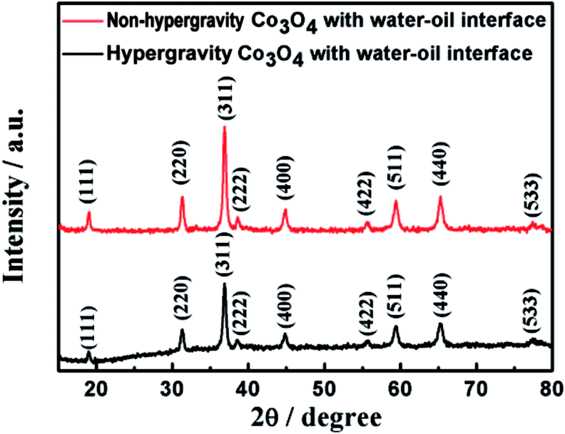 | ||
| Fig. 2 XRD patterns of Co3O4 particles based on the water–oil interface prepared by hypergravity hydrothermal method with the assistance of 0 g−1 and 1000 g−1 respectively. | ||
 | ||
| Fig. 3 HRTEM images of as-prepared Co3O4 particles based on the water–oil interface: (a) non-hypergravity Co3O4, (b) hypergravity Co3O4. | ||
However, the morphology of as-prepared Co3O4 particles, which were assembled by crystallites, was different at the 1,2-dichlorobenzene/water interface. Fig. 4 show the scanning electron microscope (SEM) images of Co3O4 particles at the 1,2-dichlorobenzene/water interface in the assistance of hypergravity of 0 g−1 and 1000 g−1, respectively. As shown in Fig. 4a and (c), the Co3O4 particles prepared at the supergravity of 0 g−1 were the Co3O4 sheet of smooth broken cross-section and no obvious pores can be observed, indicating the formation of sheets by densely packing together of Co3O4 crystallites at the 1,2-dichlorobenzene/water interface. The morphology of Co3O4 particles by the hypergravity hydrothermal method at the supergravity of 1000 g−1 was the flower with the rough broken cross-section and obvious pores were observed as shown in Fig. 4b and (d), so, we can confirm that the hypergravity Co3O4 particles showed 3D porous structure at the supergravity of 1000 g−1. The formation of Co3O4 precursor particles consists of the growth of Co3O4 precursor crystallites in the aqueous solution and their assemble or Ostwald ripening at the 1,2-dichlorobenzene/water interface. With the assistance of hypergravity, the Co3O4 precursor crystallites fast deposited at the 1,2-dichlorobenzene/water interface have poor crystalline and then the flower particles form by the Ostwald ripening of the Co3O4 precursor crystallites, while when the supergravity is 0 g−1, the crystallites deposited at the 1,2-dichlorobenzene/water interface have good crystalline, and then densely packed together at the interface due to no obvious coalescence and growth through boundary diffusion of crystallites. Their schematic mechanism for the formation is shown in Fig. S1.†
 | ||
| Fig. 4 SEM images of as-prepared Co3O4 particles by the hypergravity hydrothermal method in the following conditions: (a) 0 g−1, broken cross-section; (b) 1000 g−1, broken cross-section; (c) 0 g−1, surface and (d) 1000 g−1, surface. | ||
3.2 The rheological properties and morphology of the XG and the XG/Co3O4 nanocomposites
The rheological properties analysis was used to study the gelation kinetics by frequency sweep tests using a rheometer that monitoring the storage modulus (G′) and loss modulus (G′′), as a function of frequency in Fig. 5a. It showed that the values of storage modulus (G′) of the XG was higher than its loss modulus (G′′) between 0.01 Hz and 10 Hz, illustrating that the XG was a kind of gel-like state. However, the values of storage modulus (G′) of the PVDF was smaller than its loss modulus (G′′), showing that the mechanical properties of the XG was more robust than the PVDF. The dynamic viscosity of the XG and the PVDF binder with the scan range from 0 S−1 to 100 S−1 was shown in Fig. S4.† It was observed that the viscosity of 1 wt% XG was higher than the viscosity of 2.5 wt% PVDF. The TEM image of Co3O4/XG composite was displayed in Fig. 5b. It was shown that the XG coated on the outside of the Co3O4 particles and the XG binder can accelerate the Li-ion transfer to the surface of the Co3O4 particles. | ||
| Fig. 5 (a) Dynamic frequency sweep between 0.01 Hz to 1 Hz of the 1 wt% XG binder and the 2.5 wt% PVDF binder; (b) TEM image of the mixture of hypergravity Co3O4 and the XG binder with the ratio of 7:1.5. | ||
3.3 Electrochemical characterization
The electrochemical performance of the Co3O4 particles is related to the assembling structure of crystallites. The electrochemical performance of the Co3O4 anode electrodes with the PVDF and the XG as the binder was shown in Fig. 6. Fig. 6a presented the galvanostatic discharge curves of the different Co3O4 anode electrodes with PVDF binder at the rate of 0.5C. It was found that cycling performance of the Co3O4 anodes with the high gravity field and the water–oil interface was better than the non-hypergravity Co3O4 anode electrodes. After 50 cycles, the discharge capacities of the hypergravity Co3O4 anode with the water–oil interface had reached 237.7 mA h g−1 whereas the non-hypergravity Co3O4 anode with the water–oil interface had only 107 mA h g−1 and the non-hypergravity Co3O4 anode without the water–oil interface had a limited value of 54 mA h g−1. The discharge capacities of Co3O4 anode with the assistance of 1000 g−1 were more than 3 times higher than the other Co3O4 anodes, illustrating that Co3O4 particles with 3D porous structure have a higher discharge capacity than that of dense parking Co3O4 crystallites. It is because that the large size of the non-hypergravity Co3O4 particles without the water–oil interface make it have the smaller specific surface and longer electron/ion diffusion length, which can result in lower electron/ion diffusion efficiency and more severe volume expansion and shrinkage during charge–discharge process. The non-hypergravity Co3O4 with the water–oil interface have the larger sheet structure consisted of many Co3O4 nano-particles, which may be easy to be fractured and separated from the current collector during charge–discharge process, thus its capacity was reduced fast. In comparison with the two kinds of Co3O4 nano-particles above, the hypergravity Co3O4 nano-particles with the smaller size and 3D porous structure have the larger surface area and the shorter electron/ion diffusion length, which will accelerate the electron/ion diffusion, thus it had a higher discharge capacity. | ||
| Fig. 6 (a) Cycling performance of different Co3O4 anode electrodes with PVDF binder at the rate of 0.5C (Co3O4: acetylene black: PVDF = 80 wt%: 10 wt%: 10 wt%); (b) CV curves of the hypergravity Co3O4 electrode with XG binder at a scanning rate of 0.1 mV s−1; (c) compared CV curves of hypergravity Co3O4 electrode with XG binder and pure XG; (d) cycling performance of hypergravity Co3O4/XG and hypergravity Co3O4/PVDF (hypergravity Co3O4: acetylene black: XG/PVDF = 70 wt%: 15 wt%: 15 wt%). | ||
The cyclic voltammetry (CV) curve of the hypergravity Co3O4 anode electrodes that XG as the binder in Fig. 6b was evaluated at a voltage window range of 0.01 to 3.0 V vs. Li/Li+ at a scanning rate of 0.1 mV s−1. In the first scan, a strong reduction peak at 0.8 V was noticed, it was illustrated that the initial reduction of Co3O4 to metal Co and the formation of Li2O.35 During the process, the irreversible solid-electrolyte-interface (SEI) layer was also formed. In the following anodic scan, a peak can be observed at about 2.1 V, which was owe to the reversible oxidation of Co into cobalt oxide.36 The reduction peak was evolved into two peaks at about 0.9 V and 1.2 V and the reduction peak at 0.9 V was disappeared in the second and the third cathodic cycle, indicating the changes of the amorphization and crystallization in the Co3O4 particles. Starting from the second anodic scan, the anode peaks were shown at about 2.1 V and overlapped well. The electrochemical reaction mechanism can be summarized as follows:
| Co3O4 + 8Li+ + 8e− ↔ 3Co + 4Li2O |
In order to study the electrochemical performance of the pure XG, the CV of the pure XG binder evaluated between 0.01 V and 3.0 V in the Fig. S6† indicated that the XG binder was electrochemically inactive illustrated by the very short oxidation and reduction current. It was revealed intuitively and clearly from the comparison diagram of the CV of pure XG and Co3O4 anodes with XG as the binder shown in the Fig. 6c. Therefore, the capacity of the XG binder was ignorable likened to the capacity of the whole working electrodes.
The cycle performance of hypergravity Co3O4 anode electrodes at the rate of 0.5C made by different binders was displayed in Fig. 6d. It was observed that the hypergravity Co3O4 working electrodes with traditional PVDF binder, only displayed a low capacity of 219.9 mA h g−1 after 50 cycles. By contrast, the hypergravity Co3O4 anode electrodes with XG binder can maintain a relatively stable reversible capacity of 742.5 mA h g−1 with a columbic efficiency over 97.1% after 50 cycles, which were more than 3 times higher than the PVDF-based electrode. As shown in Table S1,† the higher capacity and cycle stability of the hypergravity Co3O4 with XG binder is superior to the previous study.37–39 The superior cycle stability of the XG-based electrode should be attributed to the higher viscosity and stronger toughness than PVDF, which can stick with hypergravity Co3O4 particles and current collectors well and retard the volume change of hypergravity Co3O4 particles during the cyclic process of charge and discharge. And the amount of the isolate hypergravity Co3O4 nanoparticles were decreased, thus improved its capacity.40,41 What's more, because the oxygen heteroatoms in the XG molecule can coordinate with the lithium ions similarly to the PEO solid electrolyte, the polarization of the hypergravity Co3O4 electrode was decreased, which also contributed to a high capacity.33,42
Fig. 7a and b, showed the charge and discharge profiles of the hypergravity Co3O4 anode electrodes with PVDF and XG as binder respectively (hypergravity Co3O4: acetylene black: XG/PVDF = 70 wt%: 15 wt%: 15 wt%), in the 1st, 10th, 20th and 30th cycles.
 | ||
| Fig. 7 Charge–discharge curves of the hypergravity Co3O4 electrode with PVDF binder (a) and XG binder (b); (c) rate capability of hypergravity Co3O4/XG electrode and hypergravity Co3O4/PVDF electrode; (d) EIS spectra of the hypergravity Co3O4 anode electrode with the XG binder and the PVDF binder in the frequency range from 0.01 Hz to 100 kHz. | ||
Comparing the two images, it is presented that the capacity decrease of the hypergravity Co3O4 anode electrodes with PVDF binder was much more serious, illustrating that the binding ability of XG was much stronger than that of PVDF because of its higher viscosity and robust mechanical property. And with the increase of the cycling, the discharge capacity of the hypergravity Co3O4 anode electrodes with XG binder is enhancive gradually between 1st cycle and 30th cycles consistent with the cycling performance in Fig. 5d, which can be explained by the electrolyte deposition mechanism previously reported: during the charge and discharge process, a gel-like polymeric layer on the surface of the active material particles, which is believed to enable additional lithium storage on its surface in a capacitive way, thus contributing to the observed gradually increasing trend.43 The rate performance of hypergravity Co3O4 electrode with the XG binder and the PVDF binder respectively studied at the rate of 0.1C, 0.2C, 0.5C, and 0.1C was shown in Fig. 7c. From the figure, we can observe that the rate capability of using XG as the binder was much more excellent than using PVDF as the binder, indicating that XG as binder of the working electrode in the lithium-ion battery can keep electrochemical performance more stable than the traditional PVDF binder.
In order to have an insight into the stable electrochemical performance of the hypergravity Co3O4 anodes with the XG binder clearly, the electrochemical impedance spectroscopy (EIS) of the hypergravity Co3O4 anodes with the XG binder and the PVDF binder after the 1st and 50th cycles were measured in the frequency range from 100 kHz to 0.01 Hz, which showed the typical Nyquist plots of the two electrodes in the Fig. 7d. It was observed that the diameter of the semicircle of the hypergravity Co3O4 electrode with the PVDF binder was much longer than the electrode with the XG binder after the 1st cycle, indicating that the Rct (charge transfer resistance) value of the electrode with the traditional PVDF binder was much higher compared with the XG-based electrode. We can also observed that the Rct of the hypergravity Co3O4 anode with the PVDF binder have a large increase after 50 cycles, while the Rct of the electrode with the XG binder almost remain the same value. It may be attributed to the higher viscosity of the XG binder, which can adhere on the surface of the hypergravity Co3O4 nanoparticles tightly and decrease the contact between the hypergravity Co3O4 nanoparticles and the electrolyte, thus, the decomposition of the electrolyte at the hypergravity Co3O4 nano-particles surfaces was reduced.42,44 In addition, the tough mechanical strength of XG-based electrode can also help to maintain the structure of the hypergravity Co3O4 electrode. Therefore, the XG as binder applied in the lithium ion battery electrode not only improved the electronic conductivity of Co3O4, but also kept stable electrochemical performance.
Fig. 8 displayed the SEM image of 3D porous structured hypergravity Co3O4 electrodes with PVDF binder and XG binder after 50 charging with the electric current density of 890 mA g−1, in comparison with the SEM images of the hypergravity Co3O4 working electrodes before cycling. As shown in Fig. 8a and c, obvious holes and cracks can be observed in the surface of the PVDF-based hypergravity Co3O4 electrode after 50 charging and discharging cycles at the current density of 890 mA g−1, and the electrode with PVDF binder was broken into small bulks because of the weak connection between PVDF and hypergravity Co3O4 particles. However, it can be found that after 50 cycles at 890 mA g−1, both the size of hypergravity Co3O4 particles and the morphology of XG-based whole electrode have no obvious change owing to the higher viscosity of the XG binder (Fig. 8b and d). The electrode with XG binder can keep a certain degree of integrity without pulverization, due to the more robust interaction between the XG binder and the hypergravity Co3O4 particles, which can effectively retard the large volume change of hypergravity Co3O4 particles during the process of charge–discharge.
 | ||
| Fig. 8 SEM images of hypergravity Co3O4 electrodes (a and b) before cycling with PVDF binder (a) and XG binder (b) and (c and d) after 50 cycles with the electric current density of 890 mA g−1 with PVDF binder (c) and XG binder (d). | ||
4. Conclusions
In this work, the Co3O4 particles with 3D porous configuration were prepared by hypergravity hydrothermal method based on the oil/water interface. The electrochemical performance of the Co3O4 anodes with 3D porous configuration was better than the dense sheet Co3O4 anodes. The 1 wt% XG binder displayed higher viscosity and more robust mechanical properties in comparison with the 2.5 wt% PVDF binder. The hypergravity Co3O4 anode with the XG binder delivered a capacity of 742.5 mA h g−1 after 50 charging and discharging cycles at the rate of 0.5C due to many functional groups of hydroxide and carboxyl of the XG molecule, while the hypergravity Co3O4 anode with the PVDF binder only displayed a lower capacity of 219.9 mA h g−1. Because of the robust strength and the high ion conductivity, the rate capability and the conductivity of the hypergravity Co3O4 anode with the XG binder was much more excellent and stable contrasting with using the PVDF binder. Therefore, the study provided a new approach to prepare Co3O4 particles by hypergravity hydrothermal method based on the oil/aqueous interface, and a promising way to decrease the volume change and enhance the stability of Co3O4 anode during charge–discharge process that composed Co3O4 and natural gels with higher viscosity and higher ion conductivity.Acknowledgements
This work was supported by the National Natural Science Foundation of China (No. 21476176, 51473123) and the Recruitment Program of Global Experts.Notes and references
- M. Armand and J.-M. Tarascon, Nature, 2008, 451, 652–657 CrossRef CAS PubMed.
- P. Poizot, S. Laruelle, S. Grugeon, L. Dupont and J.-M. Tarascon, Nature, 2000, 32, 496–499 Search PubMed.
- P.-G. Bruce, G.-B. Prof, B. Scrosati and J.-M. Tarascon, Angew. Chem., Int. Ed., 2008, 47, 2930–2946 CrossRef CAS PubMed.
- C. Zhu, P. Yang, D. Chao, X. Wang, X. Zhang, S. Chen, B.-K. Tay, H. Huang, H. Zhang and W. Mai, Adv. Mater., 2015, 27, 4566–4571 CrossRef CAS PubMed.
- B. Yin, S. Zhang, H. Jiang, F. Qu and X. Wu, J. Mater. Chem. A, 2015, 3, 5722–5729 CAS.
- Y. Wang, Y. Wang, J. Tang, Y. Xia and G. Zheng, 2014, 2, 20177–20181.
- A. Pan, Y. Wang, W. Xu, Z. Nie, S. Liang, Z. Nie, C. Wang, G. Cao and J.-G. Zhang, J. Power Sources, 2014, 255, 125–129 CrossRef CAS.
- D. Ge, H. Geng, J. Wang, J. Zheng, Y. Pan, X. Cao and H. Gu, Nanoscale, 2014, 6, 9689–9694 RSC.
- X.-W. Lou, D. Deng, J.-Y. Lee, J. Feng and L.-A. Archer, ChemInform, 2010, 20, 258–262 Search PubMed.
- F. Li, Q.-Q. Zou and Y.-Y. Xia, J. Power Sources, 2008, 177, 546–552 CrossRef CAS.
- A. Pan, J.-G. Zhang, Z. Nie, G. Cao, B.-W. Arey, G. Li, S. Liang and J. Liu, J. Mater. Chem., 2010, 20, 9193–9199 RSC.
- K. Deng and L. Li, Adv. Mater., 2014, 26, 2619–2635 CrossRef CAS PubMed.
- J. Liu, Y. Zhou, F. Liu, C. Liu, J. Wang, Y. Pan and D. Xue, RSC Adv., 2012, 2, 2262–2265 RSC.
- J.-K. Feng, S.-L. Xiong, Y.-T. Qian and L.-W. Yin, Electrochim. Acta, 2014, 129, 107–112 CrossRef CAS.
- Q. He, T. Yuan, S. Wei, N. Haldolaarachchige, Z. Luo, D.-P. Young, A. Khasanov and Z. Guo, Angew. Chem., Int. Ed., 2012, 51, 8842–8845 CrossRef CAS PubMed.
- S. Liu, J.-K. Feng, X.-F. Bian, J. Liu and H. Xu, Energy Environ. Sci., 2016, 9, 1229–1236 CAS.
- L. Zhang, J. Ni, W. Wang, J. Guo and L. Li, J. Mater. Chem. A, 2015, 3, 11782–11786 CAS.
- J. Ni, Y. Zhao, L. Li and L. Mai, Nano Energy, 2015, 11, 129–135 CrossRef CAS.
- Q. Wang, B.-W. Yu, X. Li, L.-L. Xing and X.-Y. Xue, J. Mater. Chem. A, 2016, 4, 425–433 CAS.
- F. Wu, X. Ma, J. Feng, Y. Qian and S. Xiong, J. Mater. Chem. A, 2014, 2, 11597–11605 CAS.
- H.-F. Long, M.-Y. Zhang, Q. Wang, L.-L. Xing, S. Wang and X.-Y. Xue, J. Alloys Compd., 2017, 701, 200–207 CrossRef CAS.
- L. Li, K.-H. Seng, D. Li, Y. Xia, H.-K. Liu and Z. Guo, Nano Res., 2014, 7, 1466–1476 CrossRef CAS.
- Y.-L. An, J.-K. Feng, L.-J. Ci and S.-L. Xiong, RSC Adv., 2016, 6, 103579–103584 RSC.
- H. Wu, G. Yu, L. Pan, N. Liu, M.-T. Mcdowell, Z. Bao and Y. Cui, Nat. Commun., 2013, 4, 131–140 Search PubMed.
- G. Liu, S. Xun, N. Vukmirovic, X. Song, P. Olaldevelasco, H. Zheng, V. S. Battaglia, L. Wang and W. Yang, Adv. Mater., 2011, 23, 4679–4683 CrossRef CAS PubMed.
- B. Lestriez, C. R. Chim., 2010, 13, 1341–1350 CrossRef CAS.
- F.-S. Li, Y.-S. Wu, J. Chou, M. Winter and N.-L. Wu, Adv. Mater., 2015, 27, 130–137 CrossRef CAS PubMed.
- Y.-T. Kim and E.-S. Smotkin, Solid State Ionics, 2002, 149, 29–37 CrossRef CAS.
- Z. Zhang, M. Liang, X. Liu, F. Zhao, B. Wang, W. Li and Q. Wang, RSC Adv., 2015, 5, 88419–88424 RSC.
- J.-f. Chen, Y.-H. Wang, F. Guo, A. X.-M. Wang and C. Zheng, Ind. Eng. Chem. Res., 2000, 39, 948–954 CrossRef CAS.
- L. Fang and W.-J. Li, Micro Nano Lett., 2012, 7, 353–356 Search PubMed.
- F.-M. Courtel, S. Niketic, D. Duguay, Y. Abu-Lebdeh and I.-J. Davidson, J. Power Sources, 2011, 196, 2128–2134 CrossRef CAS.
- Y.-N. Sudhakar, M. Selvakumar and D.-K. Bhat, Mater. Sci. Eng., B, 2014, 180, 12–19 CrossRef CAS.
- N. Cuesta, A. Ramos, I. Cameán, C. Antuña and A.-B. García, Electrochim. Acta, 2015, 155, 140–147 CrossRef CAS.
- S. Xiong, J.-S. Chen, X.-W. Lou and H.-C. Zeng, Adv. Funct. Mater., 2012, 22, 861–871 CrossRef CAS.
- Z.-S. Wu, W. Ren, L. Wen, L. Gao, J. Zhao, Z. Chen, G. Zhou, F. Li and H.-M. Cheng, ACS Nano, 2010, 4, 3187 CrossRef CAS PubMed.
- G.-X. Wang, Y. Chen, K. Konstantinov, J. Yao, J.-H. Ahn, H.-K. Liu and S.-X. Dou, J. Alloys Compd., 2002, 340, L5–L10 CrossRef CAS.
- Y. Liu and X.-G. Zhang, Electrochim. Acta, 2009, 54, 4180–4185 CrossRef CAS.
- M.-A. Dara, S.-H. Namb, H.-S. Abdoa, A.-A. Almajida, D.-W. Kimd, A. Qurashie and W.-B. Kimb, J. Alloys Compd., 2017, 695, 329–336 CrossRef.
- B. Koo, H. Kim, Y. Cho, K.-T. Lee, N.-S. Choi and J. Cho, Angew. Chem., Int. Ed., 2012, 124, 8892–8897 CrossRef.
- M.-H. Ryou, J. Kim, I. Lee, S. Kim, Y.-K. Jeong, S. Hong, J.-H. Ryu, T. S. Kim, J.-K. Park and H. Lee, Adv. Mater., 2013, 25, 1570 CrossRef.
- J. Liu, Q. Zhang, T. Zhang, J.-T. Li, L. Huang and S.-G. Sun, Adv. Funct. Mater., 2015, 25, 3599–3605 CrossRef CAS.
- Y. Sun, X. Hu, W. Luo, F. Xia and Y. Huang, Adv. Funct. Mater., 2013, 23, 2436–2444 CrossRef CAS.
- M.-Q. Li, M.-Z. Qu, X.-Y. He and Z.-L. Yu, Electrochim. Acta, 2009, 54, 4506–4513 CrossRef CAS.
Footnote |
| † Electronic supplementary information (ESI) available: Hypergravity mechanism image, XRD pattern, SEM patten, viscosity image and CV image. See DOI: 10.1039/c7ra02725g |
| This journal is © The Royal Society of Chemistry 2017 |