 Open Access Article
Creative Commons Attribution 3.0 Unported Licence
Liquefied walnut shell-derived carbon nanofibrous mats as highly efficient anode materials for lithium ion batteries
Lei Tao a,
Yunwu Zhengab,
Yanhua Zhanga,
Huan Mabc,
Mingwei Di*a and
Zhifeng Zheng*b
aCollege of Materials Science and Engineering, Northeast Forestry University, Harbin 150040, China. E-mail: dimingwei@nefu.edu.cn
bEngineering Laboratory for Highly-Efficient Utilization of Biomass, University Key Laboratory for Biomass Chemical Refinery & Synthesis, College of Materials Engineering, Southwest Forestry University, Kunming 650224, Yunnan Province, China. E-mail: zhengzhifeng666@163.com
cChemistry Department, Colorado School of Mines, Golden 80401, USA
First published on 23rd May 2017
Abstract
Mechanically flexible walnut shell-derived carbon nanofibers (CNFs) of 175 nm diameter were fabricated from a liquefied walnut shell—polyvinyl alcohol (PVA) hybrid solution via conventional electrospinning followed by one-step carbonization. The morphology and structure properties, as well as pore structure properties of walnut shell-derived CNFs were comprehensively characterized by field-emission scanning electron microscopy (FE-SEM), X-ray photoelectron spectroscopy (XPS), Raman spectroscopy, and their electrochemical performances were evaluated for the first time as electrode materials in lithium ion batteries, without addition of any conductive agent or binder. The walnut shell-derived CNFs mats exhibited a high specific capacity above 150 mA h g−1 with an initial efficiency of 50.4% at a current density of 100 mA g−1 and good cycle stability at different current rates (above 200 and 120 mA h g−1 at 20 and 1000 mA g−1, respectively). After 100 cycles at a current density of 100 mA g−1, walnut shell-derived CNF mats still maintained a good capacity of about 150 mA h g−1. This demonstrated the great prospect of walnut shell-derived CNF mats as electrode materials for applications in electrical energy storage.
Introduction
Rechargeable lithium batteries (LIBs) with characteristics of great safety performance, large energy density, high output voltage, long cycle life, and environmental friendliness are widely used in various applications, such as next-generation hybrid electric vehicles, and emerging smart grids.1–4 For the electrodes in LIBs, carbon materials have been holding a predominant position and been believed to be the most prospective for industrialization because of their low-cost, easy accessibility, and processability.5,6 To date, various types of carbon materials such as carbon nanotubes,7 carbon spheres,8 carbon fibers,9 and porous carbon10 have been investigated as the major anode materials for LIBs because of their high conductivity and abundant specific surface area. However, the high cost and non-renewability of the carbon precursors (such as petroleum, polyacrylonitrile, coals, etc.) as well as the complicated preparation processes restrained their extensive application. In a world subjected to a severe shortage of resources and various environmental issues, developing “green” and reliable electrode materials that combine high electrochemical performance with low-cost is still a challenge for almost every manufacturer.Nature provides a variety of renewable resources (such as cellulose,11 lignin,12 chitosan,13 peanut shells14 and protein,15 etc.) that can be demonstrated to be promising candidates as carbon electrode materials for energy applications with obvious low cost and environment benefits. Nevertheless, most of the carbon precursors are not self-supporting, binder-free, and are even manufactured from complicated and cumbersome process.
Electrospinning is a straightforward and powerful method for generating highly porous free-standing carbon nanofibers mats that could be directly used as electrode materials for energy storage devices without adding any conductive agent or binder, which could simplify the fabrication process to a great extent.16–18 In recent years, many research results indicated that the carbon fibrous mats made from natural biomass materials—lignin via electrospinning as binder-free electrodes for lithium ion batteries and supercapacitors exhibited high electrochemical performances because of their self-supporting conductive networks.19–21 However, the purity of lignin is one of the critical factors to potentially achieve good fiber electrospinnability.22 There are a variety of lignins commercially available, depending on the different chemical process and pulping techniques, such as Alcell lignin, Kraft lignin and lignosulfonate which were generated from the Alcell, Kraft and sulfite pulping process, respectively.23 However, those lignins contain inorganic or organic impurities like ashes, salts and volatile substances,24 which requires a further purification process such as acid,25 filter membrane26 and organic solvent treatment.27 Walnut shell, abandon lignocellulosic resources in the world containing abundant cellulose and lignin, is widely used as a resource for renewable energy and materials. In order to effectively utilize lignocellulosic resources to produce high value-added products, liquefaction technique was used to prepare biomass-based carbon nanofibers in our laboratory. Compared with the purification of refined lignin, liquefaction is a more convenient technique to maximize the utilization of lignocellulosic resources (e.g. walnut shell). Thus, we have strictly focused on converting this abandon lignocellulosic resource to electrospun carbon nanofibers as electrode materials for energy storage devices. Moreover, there have been no reported studies on (1) the preparation of electrospun carbon nanofibrous mats from liquefied walnut shell (2) the resultant walnut shell-derived CNFs mats as binder-free electrode materials for lithium ion batteries.
In this work, we present a straightforward method to manufacture walnut shell-derived carbon nanofibers from liquefied walnut shell via electrospinning followed by one-step carbonization. The morphology and structure of the walnut shell-derived carbon nanofibers were studied, and their electrochemical properties as anode for lithium ion batteries were investigated for the first time. The results demonstrate that the flexible and ultrafine walnut shell-derived CNF mats have a large specific surface area, fast lithium charge/discharge kinetics, and good electrochemical performance as free-standing/binder-free electrodes for applications in lithium ion batteries.
Experimental
Materials
Walnut shell (Juglans Sigillata Dod) was ground (>100 mesh) and dried in an oven at 80 °C until a constant weight was obtained, then kept in a desiccator before use. Polyvinyl alcohol (PVA) with molecular weight of Mw = 125![[thin space (1/6-em)]](https://www.rsc.org/images/entities/char_2009.gif) 000 g mol−1 and degree of hydrolysis of 88% (typical, CAS number: 8068-05-1) was purchased from Sigma-Aldrich. Phenol (C6H5OH), sulfuric acid (H2SO4, 98 wt%), formaldehyde (CH2O, 37 wt%), and sodium hydroxide (NaOH) were purchased from Sinopharm Chemical Reagent Co., Ltd., China and were all used as received without further purification.
000 g mol−1 and degree of hydrolysis of 88% (typical, CAS number: 8068-05-1) was purchased from Sigma-Aldrich. Phenol (C6H5OH), sulfuric acid (H2SO4, 98 wt%), formaldehyde (CH2O, 37 wt%), and sodium hydroxide (NaOH) were purchased from Sinopharm Chemical Reagent Co., Ltd., China and were all used as received without further purification.
Preparation of electrospinning solution
The mixture of walnut shell powder, phenol and sulfuric acid at a mass ratio of 1/4/0.03 was liquefied for 2 h at 150 °C. Afterwards, the mixture was poured into dioxane/water (8/2, v/v) at a volume ratio of 1/15. The diluted solution was filtrated and concentrated under reduced pressure to obtained impurities-free liquefied products. In the previous work,28 the liquefied phenol formaldehyde resin (LPF) was synthesized by formaldehyde (F), liquefied products (LP) with sodium hydroxide (NaOH) as catalyst (molar ratio, F/LP = 1.45/1, NaOH/LP = 0.2/1). In synthesizing resin (LPF), LP, NaOH solution and 80% of the total F were added into a three-neck flask. The solution was heated to 82 °C for 60 min. After that, the remaining 20% of F was added. Reaction temperature was increased to 87 °C and kept for 120 min under stirring, followed by cooling to room temperature. Subsequently, the synthesized LPF was diluted to 18 wt% in solid content with distilled water and 12 wt% polyvinyl alcohol (PVA) aqueous solution added into the LPF to adjust the electrospinability (mass ratio of LPF/PVA = 8/2). The mixed solution stirring was continued for 2 h. After all, the electrospinning solution was obtained.Preparation and characterization of walnut shell-derived carbon nanofibers
Electrospun nanofibers were manufactured by electrospinning device (ET-2535H, Ucalery, China) which consisted of a high voltage power supply, a syringe pump, and a roller (covered with an aluminium foil) connected to the negative pole for collecting the fibers. The spinning solution was loaded into a 5 mL plastic syringe with a 22 gauge needle which was connected to the positive pole of a voltage generator. During spinning, the distance was adjusted to 25 cm between the tip of needle and the roller, an operating voltage was ranged from 16 kV and the feeding rates of spin was maintained at 0.05 mL min−1. The carbon nanofibers were fabricated by one-step carbonation at 900 °C at a rate of 5 °C min−1 and held for 60 min in a nitrogen atmosphere.The morphology of walnut shell-derived carbon nanofiber (CNFs) was characterized using a scanning electron microscopy (SEM, JSM-5600LV). The Raman spectrometer (Raman-Station 400, PerkinElmer, MA, USA) was used to examine the experimental CNFs in terms of graphite structure. Chemical surface composition of the CNFs was determined by X-ray photoelectron spectroscopy (XPS, ESCALAB250Xi, ThermoFisher). The yield of CNFs after carbonization was characterized by thermogravimetric analysis (TGA, NETZSCH). The specific surface area and pore structure of the nanofibers were analyzed by N2 adsorption–desorption isotherms measured at −196 °C using an ASAP 2020 Plus HD88 analyzer (Micromeritics Co., Ltd.).
Electrochemical measurement
The electrochemical performance was tested with the walnut shell-derived carbon fibrous mats, lithium foil, and 1 M LiPF6 in ethylene carbonate/dimethyl carbonate (1![[thin space (1/6-em)]](https://www.rsc.org/images/entities/char_2009.gif) :
:![[thin space (1/6-em)]](https://www.rsc.org/images/entities/char_2009.gif) 1 v/v ratio) as the working electrode (without addition of any binder and conductive additive), counter electrode, and electrolyte, respectively. The cyclic voltammetry (CV) test was performed on a CHI760E electrochemical workstation (Chenhua Instrument Company, Shanghai, China) at a scan rate of 0.1 mV s−1 between 0 and 3.0 V. The electrochemical impedance spectroscopy (EIS) study was conducted using the same electrochemical work station in a frequency range of 106 to 10−2 Hz and at an ac amplitude of 5 mV. The galvanostatic charge/discharge experiments were conducted using a multi-channel Land Battery Test System over the range of 0.01–3.0 V.
1 v/v ratio) as the working electrode (without addition of any binder and conductive additive), counter electrode, and electrolyte, respectively. The cyclic voltammetry (CV) test was performed on a CHI760E electrochemical workstation (Chenhua Instrument Company, Shanghai, China) at a scan rate of 0.1 mV s−1 between 0 and 3.0 V. The electrochemical impedance spectroscopy (EIS) study was conducted using the same electrochemical work station in a frequency range of 106 to 10−2 Hz and at an ac amplitude of 5 mV. The galvanostatic charge/discharge experiments were conducted using a multi-channel Land Battery Test System over the range of 0.01–3.0 V.
Results and discussion
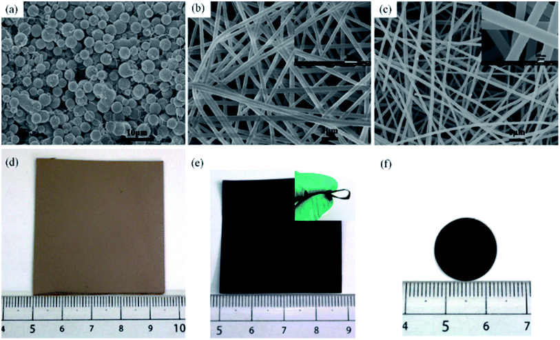
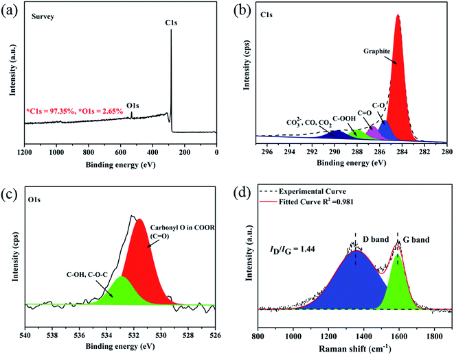
Due to lack of chain structures and/or molecular entanglements of liquefied phenolic resin (LPF), electrospinning of pristine LPF solution at any concentration is challenging and it results in electrospraying of the solution and forming spherical droplets with no fiber collectable (Fig. 1a).29 For these reasons, we must added a few amounts of PVA aqueous solution (spinning auxiliary) blend with LPF to improve its fluid properties and electrospinnability. Fig. 1 shows SEM images of as-spun walnut shell-derived nanofibers resulted from LPF/PVA hybrid solutions. As can be clearly seen from Fig. 1b, uniform nanofibers could be readily formed from LPF/PVA mixture solutions, whereas a higher amount of LPF (>90%) in the solutions resulted in beaded fibers or sprayed particles. At the same time, as-spun nanofibers and resultant carbon nanofibers exhibited long and smooth fibrous morphologies with average diameters decreasing from ∼287 nm to 175 nm (Fig. 1b–e), which are much smaller and more uniform than that of electrospun other walnut shell-derived nanofibers.19,20 Noted that the carbonized membrane still maintains good mechanical flexibility and dimensional stability, and it could be bent without breaking (Fig. 1e), which is demonstrated to be a potential material used in electrical energy storage (Fig. 1f).The walnut shell-derived CNF surface elemental composition and atomic concentrations were characterized by X-ray photoelectron spectroscopy (XPS) method, as shown in Fig. 2a–c. The two main peaks including C 1s and O 1s were seen for the survey spectrum (Fig. 2a), implied that C and O were the major component elements of walnut shell-derived CNFs, by which the carbon content was more than 97%. The C 1s spectra ranging from 280 to 296 eV can be subdivided into five obvious peaks30 corresponding to the C–C (284.38 eV), C–O (285.54 eV), C![[double bond, length as m-dash]](https://www.rsc.org/images/entities/char_e001.gif) O (286.58 eV), –COOH (287.98 eV) and CO32−, CO2, CO (289.78 eV), with the relative percentages of 66.41%, 9.94%, 7.00%, 6.94% and 6.74%, respectively, as shown in Fig. 2b. The O 1s spectrum can be fitted into two components31 centered at 531.5 eV and 532.8 eV, which could be assigned to carbonyl oxygen in COOR (C
O (286.58 eV), –COOH (287.98 eV) and CO32−, CO2, CO (289.78 eV), with the relative percentages of 66.41%, 9.94%, 7.00%, 6.94% and 6.74%, respectively, as shown in Fig. 2b. The O 1s spectrum can be fitted into two components31 centered at 531.5 eV and 532.8 eV, which could be assigned to carbonyl oxygen in COOR (C![[double bond, length as m-dash]](https://www.rsc.org/images/entities/char_e001.gif) O, 2.27%) and hydroxyl oxygen (–OH) or ether oxygen (C–O–C, 0.70%), respectively, as shown in Fig. 2c. The elements' atomic content and the results of the fits of the C 1s and O 1s region were summarized in Table 1.
O, 2.27%) and hydroxyl oxygen (–OH) or ether oxygen (C–O–C, 0.70%), respectively, as shown in Fig. 2c. The elements' atomic content and the results of the fits of the C 1s and O 1s region were summarized in Table 1.
| Content (%) | C 1s | O 1s | |||||
|---|---|---|---|---|---|---|---|
| 97.35 | 2.65 | ||||||
| C–C | C–O | C![[double bond, length as m-dash]](https://www.rsc.org/images/entities/char_e001.gif) O O |
C–OOH | CO32−, CO2, CO | C![[double bond, length as m-dash]](https://www.rsc.org/images/entities/char_e001.gif) O O |
C–OH, C–O–C | |
| BE (eV) | 284.38 | 285.54 | 286.58 | 287.98 | 289.78 | 531.58 | 532.88 |
| Content (%) | 66.41 | 9.94 | 7.00 | 6.94 | 6.74 | 2.27 | 0.70 |
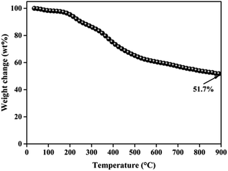
Compared with X-ray diffraction (XRD), the Raman spectroscopy is a more sensitive technique for the characterization of various forms of disordered carbons.32 Thus, Raman spectroscopy was used as to understand structural changes of walnut shell-derived CNFs during the carbonization process. Fig. 2d shows the typical features of carbon materials where two bands are depicted. The strong peak centers at 1340 cm−1 corresponds to the disorder carbon (D) band, which caused by the A1g mode, while another peak appears at 1590 cm−1 corresponds to the graphite (G) band, which caused by the E2g mode of graphite.33 In order to grasp the extract information on peak areas to calculate the intensity ratio (ID/IG), Gaussian fitting for the curve of D- and G-bands was used.34 Noted that the value of ID/IG is 1.44, which demonstrated that walnut shell-derived PCNFs are mainly disordered carbon material. Finally, the yield of walnut shell-derived nanofibers after carbonization was determined by TGA under a nitrogen atmosphere, the TGA result showed that the CNFs contained approximately 51.7 wt% yield (Fig. 3).
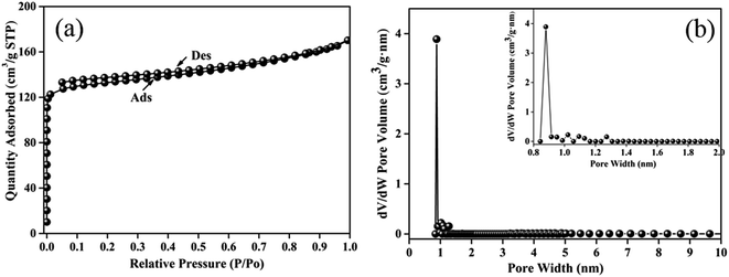
Furthermore, the N2 adsorption/desorption isotherm was tested (Fig. 4a) and analyzed by the density functional theory model (Fig. 4b) to determine the specific surface area and the porous structure of walnut shell-derived CNFs. The isotherms of the nanofibers could be classified as type I, representing the more micropores is formed.35 Walnut shell-derived carbon nanofibers have a BET surface are of 408 m2 g−1 and a microporosity ratio as high as 83% with a narrow microporous range from 0.8–1.0 nm. All the porous structure parameters are summarized in Table 2.
| SBETa (m2 g−1) | Smicrob (m2 g−1) | Vtotalc (cm3 g−1) | Vmicrod (cm3 g−1) | APWe (nm) | |
|---|---|---|---|---|---|
| a SBET: BET method.b Smicro: t-plot method.c Vtotal: total pore volume measured at P/P0 = 0.99.d Vmicro: pore volume of micropore (pore size of <2 nm).e APW: adsorption average pore width (4 V/A by BET). | |||||
| CNFs | 408 | 338 | 0.25 | 0.18 | 2.5 |
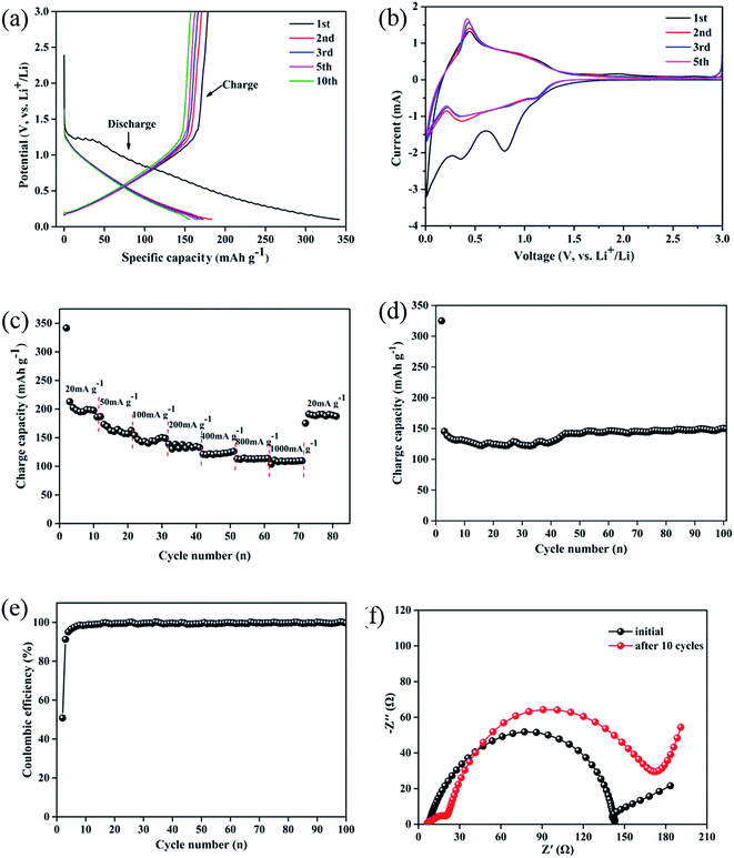
The electrochemical properties of walnut shell-derived CNFs were further investigated as anode material for LIBs. Fig. 5a shows the charge/discharge curves of the walnut shell-derived carbon fibrous mats for 1st, 2nd, 3rd, 5th, 10th cycle at a current density of 100 mA g−1 between 0.1 and 3.0 V. As seen that the walnut shell-derived CNFs electrode delivers an initial discharge and charge capacity of 341.7 and 178.5 mA h g−1, respectively. The high initial irreversible capacity loss likely originates from the solid electrolyte interphase (SEI) film formation and irreversible insertion reactions of lithium-ion into the carbon structure such as the vicinity of residual heteroatoms and some voids or cavity sites.36,37 In subsequent cycles, the irreversible capacities reduce and reversible capacities stabilize. After 10 cycle, there is still 155 mA h g−1 reversible capacity remaining, indicating good reversibility, repeatability and good lithium-ion insertion–extraction stability of the carbon mat electrode. Besides, during the initial discharge curves, an obvious voltage plateau at ∼1.3 V suggests the rapid formation of SEI caused by the decomposition of the electrolyte, contributing to the higher irreversible capacity and lower coulombic efficiencies of the electrode (∼50.4%, see in Fig. 5e).38
This can be verified with the results from the CV curves of the carbon mat (Fig. 5b). In the first scan, two well-defined reduction peaks for the walnut shell-derived CNFs electrode exist distinctly, which are located at 0.31 and 0.81 V, corresponding to the decomposition of the electrolyte on the different active surfaces of the carbon fibrous mats and the formation of SEI film, as discussed above.37 Only one small and sharp oxidation peak located at around 0.44 V is observed, showing the transformation of the lithium ion insertion–extraction from nanopores or nanocavities between the randomly stacked graphite-like domains, respectively.39 The following CV curves almost overlap after 1st cycle, indicating that the capacity decay mainly occurs in the initial cycle and the electrode exhibits a stable lithium ion insertion–extraction mechanism.
The rate capability of the walnut shell-derived CNFs electrode was investigated as shown in Fig. 5c. The result shows that the walnut shell-derived CNFs electrode exhibits an average capacity above 200 mA g−1 in the first ten cycles at 20 mA g−1. Notably, during the initial cycle, the capacity was 345 mA g−1, much higher than other cycles, while has a lower coulombic efficiency, which originates from the SEI formation, as discussed above. Upon increasing the current density, the carbon nanofibers electrode exhibits good capacities remaining at each stage, even at a very high current density (1000 mA g−1), the specific capacity still remains at 120 mA g−1. When the current density was tuned back to 20 mA g−1 after cycling at different rates, the specific capacity of the carbon electrode could be almost recovered to the original value.
Fig. 5d displays the cyclic stability of the walnut shell-derived CNFs electrode investigated at a current density of 100 mA g−1 up to 100 cycles, and the corresponding coulombic efficiency are shown in Fig. 5e. There was an interesting discovery that the initial capacity of the walnut shell-derived CNFs electrode showed an obvious capacity decrease from 151 mA g−1 to 123 mA g−1 during the first forty cycles, which caused by SEI formed on the surface of the carbon electrode. Especially, in subsequent ten cycles, the sample exhibits good cyclic performance and a significant capacity recover to 150 mA g−1. This phenomenon could be attributed to a layer of gelatinous material (which can provide capacity) formation on the surface of the carbon electrode or SEI crack to generate a new thinner SEI film which led to the capacity increasing.40,41 During the last fifty cycles, the walnut shell-derived CNFs electrode still retained to the original capacity of ∼150 mA g−1 and the coulombic efficiency was still around 99% except for the initial columbic efficiency of 50.4%. The good electrochemical stability and high degree of reversibility suggests that walnut shell-derived CNFs is relevant for electrode capacitance applications.
To better understand the electrochemical performances of the walnut shell-derived CNFs electrode, electrochemical impedance spectroscopy (EIS) study was also conducted before and after ten charge/discharge cycles at current density of 100 mA g−1, shown as Fig. 5f. Before charge/discharge cycle, the impedance plot is composed of a depressed semicircle at high to medium frequency range, corresponding to the charge-transfer resistance (Rct) at the electrolyte/electrode interface, and a sloped tail in the low-frequency region, corresponding to the Warburg impedance refers to the lithium-ion diffusion process within the solid material.42 After ten charge/discharge cycles, the curve for the walnut shell-derived CNFs electrode consists two semicircles, the first semicircle (at high frequency) can be ascribed to the SEI film resistance during cycling process and the second semicircle is due to the Rct.43 The value of SEI film resistance and Rct before charge/discharge cycles is 142.8 Ω which increases to 173.3 Ω after 10 cycles. Compared with the other carbonaceous electrodes which are made from mesoporous carbon,44 activated carbon45 and porous carbon,10 the walnut shell-derived CNFs electrode is much smaller. The lower surface charge-transfer resistance of the walnut shell-derived CNFs electrode could be attributed to the favorable charge- and lithium-ion – transfer processes within the nanofiber webs, implying its good electrochemical performance.
Conclusion
In the present work, walnut shell-derived CNF mats with mechanical flexibility were obtained through electrospinning of LPF/PVA hybrid solution, followed by one-step carbonization process. Due to the characteristics of abundant micropore structure (∼338 m2 g−1), high specific surface area (∼408 m2 g−1), and much thinner diameter (∼175 nm), the walnut shell-derived CNFs mats were studied as electrode materials for lithium ion batteries without addition of any conductive agent or binder. As a consequence, the carbon mats showed high performance, exhibiting a reversible charge capacity of about 150 mA h g−1 and initial efficiency of 50.4% at a current density of 100 mA g−1 with good rate capability (120 mA h g−1 at 1000 mA g−1), and excellent cycling stability (150 mA h g−1 over 100 cycles at 100 mA g−1). The excellent performance, combined with inexpensive biomass, convenient fabrication technique and economical synthesis method, make walnut shell-derived CNFs to be sustainable electrode material for lithium ion batteries.Acknowledgements
The work was supported by the Key Project of Yunnan Provincial Science Foundation (No. 2014FA034), and the National natural Science Foundation of China (No. 31670599 and No. 31160147).Notes and references
- Y. M. Sun, N. Liu and Y. Cui, Nat. Energy, 2016, 1, 16071 CrossRef CAS.
- N. Liu, Z. D. Lu, J. Zhao, M. T. McDowell, H. W. Lee, W. T. Zhao and Y. Cui, Nat. Nanotechnol., 2014, 9, 187 CrossRef CAS PubMed.
- B. Scrosati and J. Garche, J. Power Sources, 2010, 195, 2419 CrossRef CAS.
- J. M. Tarascon, Philos. Trans. R. Soc., A, 2010, 368, 3227 CrossRef PubMed.
- M. E. Spahr, D. Goers, A. Leone, S. Stallone and E. Grivei, J. Power Sources, 2011, 196, 3404 CrossRef CAS.
- H. B. Lin, W. Z. Huang, H. B. Rong, J. N. Hu, S. W. Mai, L. D. Xing, M. Q. Xu, X. P. Li and W. S. Li, J. Power Sources, 2015, 287, 276 CrossRef CAS.
- C. Kang, M. Patel, B. Rangasamy, K. N. Jung, C. L. Xia, S. Shi and W. Choi, J. Power Sources, 2015, 299, 465 CrossRef CAS.
- K. Tang, R. J. White, X. K. Mu, M. M. Titirici, P. A. Aken and J. Maier, ChemSusChem, 2012, 5, 400 CrossRef CAS PubMed.
- H. Bi, J. Chen, W. Zhao, S. R. Sun, Y. F. Tang, T. Q. Lin, F. Q. Huang, X. D. Zhou, X. M. Xie and M. H. Jiang, RSC Adv., 2012, 3, 8454 RSC.
- L. W. Ji and X. W. Zhang, Nanotechnology, 2015, 20, 155705 CrossRef PubMed.
- J. Li, R. Klöpsch, S. Nowak, M. Kunze, M. Winter and S. Passerini, J. Power Sources, 2011, 196, 7687 CrossRef CAS.
- S. X. Wang, L. P. Yang, L. P. Stubbs, X. Li and C. B. He, ACS Appl. Mater. Interfaces, 2013, 5, 12275 CAS.
- L. L. Chai, Q. T. Qu, L. F. Zhang, M. Shen, L. Zhang and H. H. Zheng, Electrochim. Acta, 2013, 105, 378 CrossRef CAS.
- G. T. K. Fey, Y. Y. Lin, K. P. Huang, Y. C. Li, T. P. Kumar, Y. D. Cho and H. M. Kao, Adv. Mater. Res., 2012, 415, 1572 Search PubMed.
- L. Wang, D. Wang, Z. H. Dong, F. X. Zhang and J. Jin, Small, 2014, 10, 998 CrossRef CAS PubMed.
- H. G. Wang, S. Yuan, D. L. Ma, X. B. Zhang and J. M. Yan, Energy Environ. Sci., 2015, 8, 1660 CAS.
- V. Aravindan, J. Sundaramurthy, P. S. Kumar, Y. S. Lee, S. Ramakrishna and S. Madhavi, Chem. Commun., 2015, 51, 2225 RSC.
- M. J. Laudenslager, R. H. Scheffler and W. M. Sigmund, Pure Appl. Chem., 2010, 82, 2137 CrossRef CAS.
- W. E. Tenhaeff, O. Rios, K. More and M. A. McGuire, Adv. Funct. Mater., 2014, 24, 86 CrossRef CAS.
- W. L. Zhang, J. Yin, Z. Q. Lin, H. B. Lin, H. Y. Lu, Y. Wang and W. M. Huang, Electrochim. Acta, 2015, 176, 1136 CrossRef CAS.
- H. R. Lu, A. Cornell, F. Alvarado, M. Behm, S. Leijonmarck, J. B. Li, P. Tomani and G. Lindbergh, Materials, 2016, 9, 127 CrossRef.
- E. Frank, L. M. Steudle, D. Ingildeev, J. M. Spörl and M. R. Buchmeiser, Angew. Chem., Int. Ed., 2014, 53, 5262 CrossRef CAS PubMed.
- S. Laurichesse and L. Avérous, Prog. Polym. Sci., 2014, 39, 1266 CrossRef CAS.
- M. Lallave, J. Bedia, R. Ruiz-Rosas, J. Rodríguez-Mirasol, T. Cordero, J. C. Otero, M. Marquez, A. Barrero and I. G. Loscertales, Adv. Mater., 2007, 23, 4292 CrossRef.
- V. Poursorkhabi, A. K. Mohanty and M. Misra, J. Appl. Polym. Sci., 2015, 1322 Search PubMed.
- S. C. Wang, Y. Li, H. X. Xiang, Z. Zhou, T. K. Chang and M. F. Zhu, Compos. Sci. Technol., 2015, 119, 20 CrossRef CAS.
- X. Y. You, K. Koda, T. Yamada and Y. Uraki, Holzforschung, 2015, 69, 1097 CrossRef CAS.
- C. Ma, Y. Song, J. L. Shi, D. Q. Zhang, M. Zhong, Q. G. Guo and L. Liu, Mater. Lett., 2012, 76, 211 CrossRef CAS.
- C. Lai, Z. Zhou, L. Zhang, X. Wang, Q. Zhou, Y. Zhao, Y. Wang, X. F. Wu, Z. Zhu and H. Fong, J. Power Sources, 2014, 247, 134 CrossRef CAS.
- Y. Huang and G. Zhao, Holzforschung, 2016, 70, 195 CAS.
- G. Milczarek, A. Ciszewski and I. Stepniak, J. Power Sources, 2011, 196, 7882 CrossRef CAS.
- Y. Huang, L. Peng, Y. Liu, G. Zhao, J. Y. Chen and G. Yu, ACS Appl. Mater. Interfaces, 2016, 8, 15205 CAS.
- Y. X. Huang, E. Ma and G. J. Zhao, RSC Adv., 2015, 5, 70287 RSC.
- S. X. Hu, S. L. Zhang, N. Pan and Y. L. Hsieh, J. Power Sources, 2014, 270, 106 CrossRef CAS.
- M. X. Wang, Z. H. Huang, T. Shimohara, F. Kang and K. Liang, Chem. Eng. J., 2011, 170, 505 CrossRef CAS.
- J. Yao, G. X. Wang, J. H. Ahn, H. K. Liu and S. X. Dou, J. Power Sources, 2003, 114, 292 CrossRef CAS.
- Y. L. Cao, L. F. Xiao, M. L. Sushko, W. Wang, B. Schwenzer, J. Xiao, Z. Nie, L. V. Laxmikant, Z. G. Yang and J. Liu, Nano Lett., 2012, 12, 3783 CrossRef CAS PubMed.
- P. Guo, H. H. Song, X. H. Chen, L. L. Ma, G. H. Wang and F. Wang, Anal. Chim. Acta, 2011, 688, 146 CrossRef CAS PubMed.
- R. Alcántara, P. Lavela, G. F. Ortiz and J. L. Tirado, Electrochem. Solid-State Lett., 2005, 8, A222 CrossRef.
- V. A. Agubra, L. Zuniga, D. Flores, J. Villareal and M. Alcoutlabi, Electrochim. Acta, 2016, 192, 529 CrossRef CAS.
- H. L. Fei, Z. W. Peng, L. Li, Y. Yang, W. Lu, E. L. Samuel, X. Fan and J. M. Tour, Nano Res., 2014, 7, 502 CrossRef CAS.
- Z. Ma, Z. Li, K. Hu, D. Liu, J. Huo and S. Wang, J. Power Sources, 2016, 325, 71 CrossRef CAS.
- Y. Li, L. B. Kong, M. C. Liu, W. B. Zhang and L. Kang, J. Energy Chem., 2016, 1 DOI:10.1016/j.jechem.2016.11.017.
- H. Q. Wang, Z. B. Zhao, M. Chen, N. Xiao, B. B. Li and J. S. Qiu, New Carbon Mater., 2014, 29, 280 CrossRef.
- L. W. Ji and X. W. Zhang, Electrochem. Commun., 2009, 11, 684 CrossRef CAS.
| This journal is © The Royal Society of Chemistry 2017 |

