 Open Access Article
Creative Commons Attribution 3.0 Unported Licence
WGUs sensor based on integrated wind-induced generating units for 360° wind energy harvesting and self-powered wind velocity sensing
Wenlong Li†
,
Hengyu Guo†,
Yi Xi *,
Chuanshen Wang,
Muhammad Sufyan Javed,
Xiaona Xia and
Chenguo Hu
 *
*
Department of Applied Physics, The State Key Laboratory of Mechanical Transmission, Chongqing University, Chongqing 400044, PR China. E-mail: xiyi.xi@163.com; hucg@cqu.edu.cn; Fax: +86 23 65678362; Tel: +86 23 65678362
First published on 27th April 2017
Abstract
Wind, as a natural power source, can be used to produce electricity using wind generators. However, detecting wind velocity has been challenging because wind always blows in a random direction. In this study, we design a self-powered wind velocity sensor based on integrated wind-induced generating units (WGUs) to harvest wind energy from all directions in a plane and as a self-powered wind velocity sensor (denoted as WGUs sensor). A wind-induced generating unit consists of two parallel plate Cu-electrodes (size 1.5 × 4 cm2, gap 0.5 cm) and a polytetrafluoroethylene (PTFE) thin film between them. The W-TGUs sensor can be effectively used to harvest wind energy from all directions in a plane by integrating the W-TGUs in circular and vertical directions. The output current and voltage of every WGU are 1–3.5 μA, and 13–20 V under a wind speed of 6–27 m s−1. The output rectified current of WGUs, with vertically integrated one to five WGUs, was 1.3–6.8 μA under a wind speed of 8 m s−1. Moreover, the W-TGUs sensor can detect a wind velocity from all directions on a plane with a resolution ratio of 0.13 (m s−1) Hz−1 and a response time of 0.15 s, which is a very important advantage as a self-powered wind velocity sensor. The output power of the WGUs sensor can be greatly enhanced by increasing the number of WGUs. This study provides a novel design for harvesting wind energy and sensing wind velocity from a random direction on a plane.
1. Introduction
Nature has a wealth of energy reserves, and wind is an important source of energy. In fact, people have been collecting wind energy for various applications. As a result, the detection of wind velocity is important for the scientific design of air-based vehicles and airflow related equipment, morphological studies of plants and flying animals, and in meteorology. It is known that anemometers are used to measure wind speed, while vanes are used to measure wind direction, which are commonly used for meteorology. For scientific design purposes, wind velocity sensors are mainly based on ultrasonic vortex measurements and pressure deviation measurements.1,2 Most of them are big, expensive, have long response times, a low resolution ratio and only detect wind velocity in one direction or a narrow range of angles with the necessary power supply. Therefore, it is necessary to construct better wind velocity sensors, having smaller volumes, a lower costs, shorter response times, higher resolution ratios and the ability of simultaneously detecting wind velocity in various directions. Moreover, a wind velocity sensor, capable of collecting surrounding energy that can be converted into electrical energy to sustain its operation, is highly desired.The triboelectric nanogenerator was invented in 2012.3 It was used to convert mechanical energy into electricity through the combination of triboelectrification and electrostatic induction. The TENG can be applied to harvest all types of mechanical energies in our daily life, such as human body motions, mechanical vibrations, triggering and transmission from human activities, natural wind, flowing water and waves.4–14 Recently, TENGs have been used to harvest wind energy and as self-powered wind speed sensors.15–21 However, these TENGs can only harvest wind energy in a narrow range of angles. They can hardly be used to monitor wind speed in real-time and all azimuth directions.
Herein, we designed a self-powered wind velocity sensor based on integrated wind-induced generating units for harvesting wind energy and detecting airflow velocities up to 360°. The airflow-induced generating unit consisted of two parallel plate Cu-electrodes (size 1.5 × 4 cm2, gap 0.5 cm) and a polytetrafluoroethylene (PTFE) thin film between the electrodes. For harvesting more wind energy from all angles, the WGUs sensor was obtained by integrating WGUs in circular and vertical directions. The output current and voltage of every WGU was 1–3.5 μA, and 13–20 V under a wind speed of 6–27 m s−1. The output rectified current of WGUs with one to five vertically integrated WGUs was 1.3–6.8 μA under a wind speed of 8 m s−1. Moreover, the WGUs sensor detected wind velocity from all directions in a plane with a resolution ratio of 8 Hz (m s−1)−1 or 0.13 (m s−1) Hz−1 and a response time of 0.15 s, which is a very important advantage as self-powered wind velocity sensor. Unlike a traditional wind velocity sensor, the WGUs sensor has a smaller volume, lower cost, shorter response time, higher resolution ratio and can simultaneously detect wind velocity in various directions. Moreover, the WGUs sensor can collect surrounding energy and convert it into electric energy and operate automatically. In addition, a solar cell was installed on the top of the WGUs sensor, which enabled an additional function of harvesting solar energy. This study provides a novel design for simultaneously harvesting wind energy and sensing wind velocity from random directions. This novel, advanced and self-powered wind velocity may be applied for practical applications in people's lives. It also provides a useful design of a multi-functional device for simultaneously harvesting wind energy, solar energy and sensing wind velocity from random directions.
2. Experimental
2.1 Fabrication of WGU and WGUs sensor
The wind-induced generating unit (WGU) consisted of two parallel plate Cu electrodes (size 1.5 × 4 cm2, gap 0.5 cm) and a polytetrafluoroethylene (PTFE) thin film (50 μm in thickness) between the electrodes. To increase the electric charge density on the surface of the PTFE film and then enhance the efficiency from wind energy into electric energy, the PTFE film was etched by an inductively coupled plasma reactive-ion technique to produce a nanostructure on the surface. Herein, one end of PTFE film was fixed and the other was suspended in the gap so that the PTFE film could freely flap the two electrodes when wind blew. A WGU sensor can be integrated with only eight WGUs in the eight directions of a plane, such as north, northeast, east, east-south, south, southwest, west, and west-north, and can harvest wind energy and wind information in all azimuth directions. To increase the output power, we set five WGUs vertically in every direction. In above, all units of WGUs sensor for energy conversion from the wind energy to electric energy, and they should be in parallel after be rectificated because of existing different phase position between different units' output current, but only first layer of WGUs are set as wind direction sensor for sample and effective design. Every unit of the first layer of eight WGUs was in series with an LED, and the LED could detect the wind direction due to be lighting with wind energy from the corresponding direction.2.2 Fabrication of WGUs sensor and SC hybrid device
In this hybrid device, the Si solar cell (SC) was built on the top of the WGUs sensor. It should be in parallel with the WGUs sensor after rectification because of the existing different phase positions between different generators. The WGUs sensor and SC hybrid device can individually and simultaneously harvest wind energy and solar energy. The working area of the SC is about 40 cm2.2.3 Characterization of the WGUs sensor
The micro-morphology of the PTFE surface was characterized using a field emission scanning electron microscope (Nova 400 Nano SEM). The output performance of the WGUs sensor was measured using a programmable electrometer (Keithley 6514) and a Data Acquisition Card (NI PCI-6259). To prove its application, WGUs sensor can directly power a temperature sensor, 43 LEDs or a capacitor of 20 μA. During the test, the device was fixed on an optical table, while an air blower (Zero Corp McLean Engineering PR368C60) or an air compressor (Hezheng Machine Model AE1012) was used to drive the WGUs sensor. The device concatenates a rotameter to monitor the speed of wind. The humidity of air was 45% in the performed tests.3. Result and discussion
3.1 Working principle of the WGUs sensor
Fig. 1a and b show the schematics of the WGUs sensor and the WGU structure, respectively. The WGU was structured as a Cu/PTFE film/Cu, and the WGUs sensor was integrated by WGUs vertically in a circle. One end of PTFE film was fixed and the other was suspended in the gap so that the PTFE film could freely flap the two electrodes when the wind blew. A WGU sensor could only be integrated by eight WGUs in the eight directions of a plane, such as north, northeast, east, east-south, south, southwest, west, and west-north, and harvest wind energy and wind information from any direction on a plane. In this study, five WGUs vertically in every direction were used to increase the output power. In the WGUs sensor, all units of the WGUs sensor collected wind energy and converted it into electric energy. Moreover they should be connected in parallel after be rectified because of existing different phase position between different units' output current, but only first layer of WGUs are set as wind direction sensor for sample and effective design. Every unit of the first layer of eight WGUs was in series with an LED, and the LED could detect wind direction due to lighting-up with wind energy from the corresponding direction. To increase the electric charge density on the surface of the PTFE film and enhance the efficiency of conversion of wind energy to electric energy, the PTFE film was etched by an inductively coupled plasma reactive-ion technique to produce a nanostructure on the surface. Its surface charge density could reach −2e−6C/m2 after the above disposing, as shown in Fig. 1c. The photographs of the WGU and WGUs are shown in Fig. 1d and e, respectively, which illustrate that the size of a WGU is 1.5 × 4 cm2 with a gap of 0.5 cm, and the diameter of the WGUs sensor is 12 cm with five layers of WGUs. The WGUs sensor can be enlarged by increasing the layers of the WGU.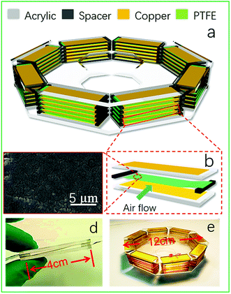 | ||
| Fig. 1 (a and b) Schematic diagrams of the WGUs sensor and WGU structures. (c) The SEM image of the PTFE film. (d and e) The photographs of the WGU and WGUs sensor. | ||
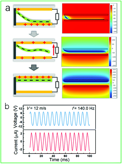
Fig. 2a shows the working principle of a WGU based on the combination of the triboelectric effect and electrostatic induction (left), and its potential distribution is calculated by a finite-element simulation (right). The potential distribution of a WGU was calculated from a finite-element simulation using Comsol Multiphysics software. In the simulation, the necessary parameters were set as follows. The gap of the Cu electrodes was 1.5 mm, the thickness of the PTFE film was 50 μm, and the electric charge density on the surface of the PTFE film was −2e−6C/m2. A WGU is considered to be a flat-panel capacitor with an external load of R. When wind blows through the WGU, its PTFE film contacts/separates on/from the top/bottom electrode. The induced charges on the top/bottom electrode continually change and produce electrical current in the external circuit during the contact and separation processes. Fig. 2b shows the output current and output voltage curve of one WGU under a wind speed of 12 m s−1. The output voltage was about 8 V, the output current was about 2.3 μA and the output frequency was about 140 Hz with a wind speed of 12 m s−1. Because the output frequency (including the frequency of the output current and output voltage) for every WGU was related to wind speed, the output frequency could also be used to detect wind speed.
3.2 Self-powered wind velocity sensor by harvesting wind energy in 360°
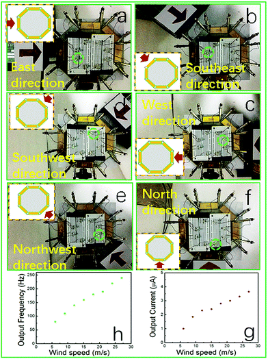
To intuitively prove and qualitatively investigate the self-power wind velocity sensor by harvesting wind energy in 360°, the LEDs were connected in a series in the integrated WGUs, as shown in Fig. 3a–f. For the integrated WGUs sensor, it included five layers, and every layer had eight WGUs. The eight WGUs were simply and effectively designed, and set in eight directions of a plane such as north, northeast, east, east-south, south, southwest, west, and west-north. One LED was connected in series for every direction in the first layer, and the LED could detect wind direction due to lighting-up with wind energy from the corresponding direction. When the wind was blowing in any direction, the corresponding LED lit to illustrate the wind direction, as shown in Fig. 3a–f. The WGUs sensor could successfully detect wind direction and harvest the corresponding wind energy in the eight directions from the visual images. In addition, if the WGU sensor is set in any plane without moving, it also detects wind velocity and harvests corresponding wind energy from any direction excluding the eight azimuthal angles above on the plane. Furthermore, it can detect the adjacent to two direction by the neighboring two lighted LEDs. For example, when wind blows one azimuthal angle which was between north and northeast, it will be divided into two parts by the sharp between in north and northeast, and flow though the WGUs of north and northeast, then the relevant two LEDs will be lighted, then we can find the wind direction from an azimuthal angle between north and northeast. Therefore, we also can harvest wind energy from other directions and judge the direction of wind. Based on the above all analysis, for harvesting wind energy and determining wind direction in these eight directions, it should be essentially equal to the harvest wind energy and wind direction in various azimuthal angles. Overall the WGUs sensor could harvest wind energy and detect wind direction at various azimuthal angles up to 360° on any plane.To quantitatively investigate the properties of the WGUs sensor for detecting wind speed, the relationship between the wind speed and the corresponding output current frequency of a WGU was systematically measured. The measurement results are shown in Fig. 3g. The output current frequency increase from 1 μA at 80 Hz to 3.5 μA at 240 Hz, when wind speed was varied from 6 to 27 m s−1, from which we can see that there was a good linear relationship between wind speed and the corresponding frequency of the output current for a WGU. It indicates that the frequency of the output current of a WGU can be used as a variable for detecting wind speed in a large range (6–27 m s−1). Based on the curve of the output current frequency–wind speed in Fig. 3g, when wind speed was 6–27 m s−1, the relationship between them was  , where v is wind speed, f is the frequency of the output current of a WGU, and 0.13 (m s−1) Hz−1 is the slope of wind speed–current frequency curve (denoted as resolution ratio of the WGUs sensor). This indicates that the wind speed will change to 0.13 m s−1 with a frequency of 1 Hz for the output current, or the frequency of the output current will be changed into 8 Hz with a 1 m s−1 wind speed. In addition, based on our experimental conditions (limited tools in this work), we could only measure the wind speed in the range of 6–27 m s−1. The WGUs sensor could harvest the wind energy in the scope of wind speed. On the basis of the research above, we determined that the WGUs sensor could effectively measure the wind speed in a range larger than 6–27 m s−1.
The WGUs sensor had a shorter response time than traditional wind velocity sensors. To quantitatively investigate its response time, we observed an enlargement of the current–time curves when the wind stopped. The response time was about 0.15 s, as shown in Fig. 3h.
The above experimental results indicate that the device can be used as a self-powered wind velocity sensor to simultaneously detect wind direction and wind speed. The sensor operated in a large range of wind speeds and at a high resolution ratio, with a small response time and in various azimuthal angles up to 360° on any plane.
3.3 Using WGUs to power LEDs
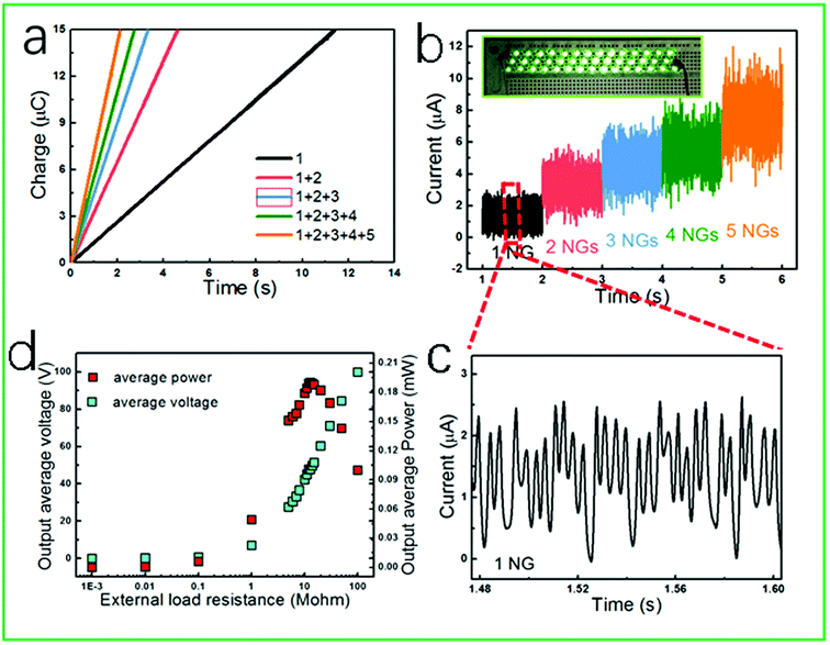
To explore potential applications, the five WGUs were chosen as a power supply with connection of 1–5 WGUs in parallel at the wind speed of an air compressor. Fig. 4 a shows the charge curves of a TENG assembled by 1–5 WGUs, indicating that the charge quantity can reach to 10 μC in 11.15–2.0 s with 1–5 WGUs connected in parallel. Fig. 4b shows the current curves of the TENG assembled by 1–5 WGUs in parallel after being rectified, from which the average output current could be derived as 1.3 μA, 2.7 μA, 4.3 μA, 5.5 μA and 6.8 μA. The average output current linearly increased with the increase in number of WGUs. The inset shows that the TENG, with five WGUs, could light up 43 LEDs in series driven by wind at 12 m s−1. The Fig. 4c is the enlargement of output current after be rectified. Fig. 4d presents the output average voltage and output average power of a WGU versus an external load resistance, from which we can see that the maximum power reached 20 mW m−2, with an external load resistance of 12 MΩ. These results indicate that the WGU had a high output power density and could be used to drive individual or multiple electrical devices.3.4 SC and WGUs hybrid device
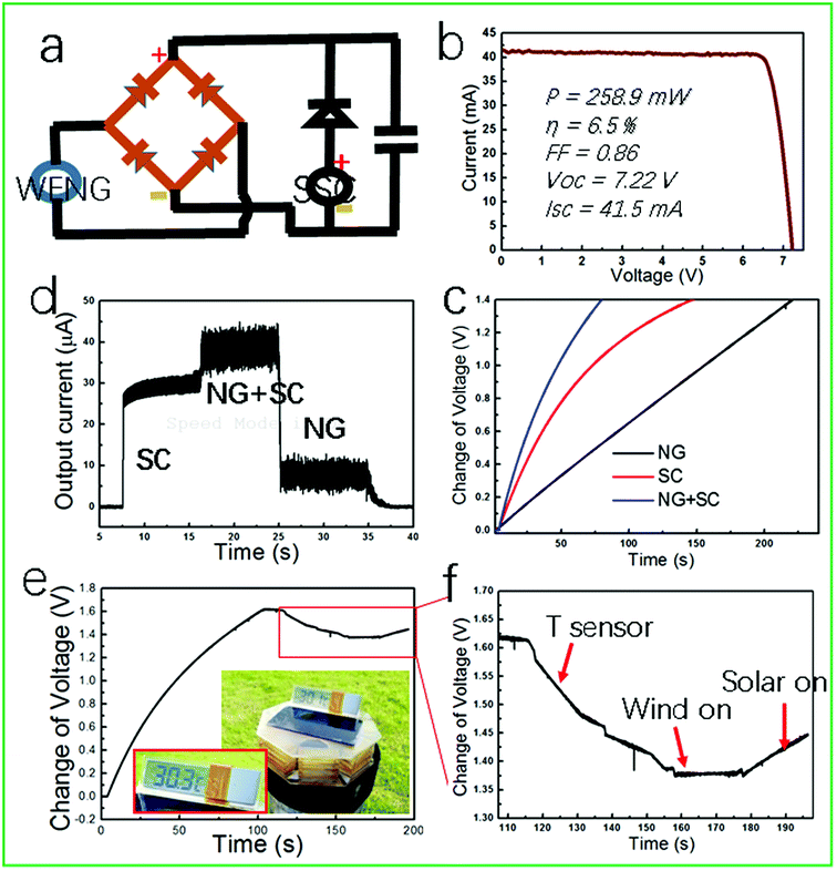
Solar energy and wind energy abundantly exists in our surroundings. If a device can simultaneously harvest both light and wind energy, it can work either in the absence of light or wind, as well as in the presence of both light and wind. Solar cells (SC) represent a new class of photovoltaic devices, which have attracted much attention due to good qualities such as low costs and convenience for multifunction.20 As a result, the SC and WGUs hybrid device are promising because they can harvest both light and wind energy. The rectification and connection circuit of the hybrid device with a capacitor (10 μF) is shown in Fig. 5a. The I–V curve of SC, under irradiation of simulated solar light of 100 mW cm−2, is shown in Fig. 5b. The five assembled WGUs and SC hybrid device can produce a high and stable power output. The capacitor charged to 1.4 V needs 240 s by WGU, 150 s by SC and 75 s by WGUs + SC as shown in Fig. 5c. Moreover, Fig. 5d shows that the rectified output current was found to be 10 μA, 30 μA and 40 μA on harvesting individual wind energy, solar energy and simultaneously harvesting wind and solar energy, illustrating the effectively increased energy. The digital photographs in Fig. 5e show the hybrid device driving a temperature sensor. The voltage output produced by the hybrid device increased with wind and irradiation time since there was a capacitor in the circuit (Fig. 5a). However, when we cut off wind and light, only a small voltage drop was observed, and the sensor still worked with the released electricity from the capacitor. In Fig. 5e, the voltage–time curve was obtained under a wind speed of 8 m s−1, and the output rectified current was 6.8 μA. The normal work current of the temperature sensor is about 6.8 μA, so the voltage drop without generate on by wind generator and solar cell. To power the temperature sensor, the voltage change of the capacitor decreased from 1.62 V to 1.38 V in 60 s when wind and light were turned off, but the drop trend was not observed when the wind was turned on to generate the same current. The voltage increased when wind and light were turned on. This results indicates whether the sensor can work under fluctuating wind and solar conditions.4. Conclusions
In summary, the assembled WGUs sensor based on WGUs has been designed for harvesting wind energy up to 360° on any plane, and can be used as a self-powered wind velocity sensor to detect wind direction and speed. The working principle of the WGUs sensor for harvesting wind energy in 360°, and the sensor has been discussed in detail. For a self-powered wind sensor, the LEDs can be a sign of the wind direction, and the output current frequency of a WGU, without rectification, can be used as a measure of the wind speed. The resolution ratio of the WGUs sensor can reach 0.13 (m s−1) Hz−1, and the response time can approach 0.15 s. The stable output was illustrated by five assembled WGUs, which can be used to light 43 LEDs and charge a commercial capacitor to 10 μC in 2 s. When WGUs were hybridized with SC, it could either individually or simultaneously harvest light energy and wind energy to drive a temperature sensor. In addition, the WGUs sensor has a smaller volume and lower cost than other sensors. This study has significant potential for utilizing wind energy and self-powered wind velocity sensor system.Acknowledgements
This study was supported by the NSFCQ (cstc2014jcyjA50030), the Graduate Scientific Research and Innovation Foundation of Chongqing, China (Grant No. CYS16016), the Chongqing University Postgraduates' Innovation Project (No. CYS15016), NSFC (51572040, 51402112), the Fundamental Research Funds for the Central Universities (No. CDJZR12225501, CQDXWL-2014-001, and No. 106112015CDJXY300004), the National Key Research and Development Programs – Intergovernmental International Cooperation in Science and Technology Innovation Project (Grant No. 2016YFE0111500), and the large-scale equipment sharing fund of Chongqing University.References
- M. Schock and E. J. Spillar, Opt. Lett., 1998, 23, 150 CrossRef CAS PubMed.
- H. L. Kent, B. J. Jay and K. H. Ronald, AIAA J., 2007, 45, 2204 CrossRef.
- F. R. Fan, Z. Q. Tian and Z. L. Wang, Nano Energy, 2012, 1, 328 CrossRef CAS.
- Z. L. Wang, ACS Nano, 2013, 7, 9533 CrossRef CAS PubMed.
- X. M. He, H. Y. Guo and X. L. Yue, Nanoscale, 2015, 7, 1896 RSC.
- Y. F. Hu, J. Yang, Q. S. Jing, S. M. Niu, W. Z. Wu and Z. L. Wang, ACS Nano, 2013, 7, 10424 CrossRef CAS PubMed.
- B. Saravanakumar, R. Mohan and K. Thiyagarajan, RSC Adv., 2013, 3, 16646 RSC.
- X. J. Zhao, G. Zhu and Z. L. Wang, ACS Appl. Mater. Interfaces, 2015, 7, 6025 CAS.
- Y. H. Ko, G. Nagaraju and J. S. Yu, RSC Adv., 2015, 5, 6437 RSC.
- T. C. Hou, Y. Yang, H. Zhang, J. Chen, L. J. Chen and Z. L. Wang, Nano Energy, 2013, 2, 856 CrossRef CAS.
- X. L. Yue, Y. Xi and C. G. Hu, RSC Adv., 2015, 5, 32566 RSC.
- J. M. Liu, N. Y. Cui and L. Gu, Nanoscale, 2016, 8, 4938 RSC.
- J. Chen, J. Yang, Z. Li, X. Fan, Y. Zi, Q. Jing, H. Guo, Z. Wen, K. C. Pradel, S. Niu and Z. L. Wang, ACS Nano, 2015, 9, 3324 CrossRef CAS PubMed.
- H. Y. Guo, X. M. He, J. W. Zhong, Q. Z. Zhong, Q. Leng, C. G. Hu, J. Chen, L. Tian, Y. Xi and J. A. Zhou, J. Mater. Chem. A, 2014, 2, 2079 CAS.
- X. Zhao, Z. Shang and G. Luo, Microelectron. Eng., 2015, 142, 47 CrossRef CAS.
- Y. Yang, G. Zhu, H. L. Zhang, J. Chen, X. D. Zhong, Z. H. Lin, Y. J. Su, P. Bai, X. N. Wen and Z. L. Wang, ACS Nano, 2013, 7, 9461 CrossRef CAS PubMed.
- H. Y. Guo, J. Chen, L. Tian, Q. Leng, Y. Xi and C. G. Hu, ACS Appl. Mater. Interfaces, 2014, 6, 17184 CAS.
- S. Lee, Adv. Funct. Mater., 2013, 23, 2445 CrossRef CAS.
- F. Fei, J. D. Mai and W. J. Li, Sens. Actuators, A, 2012, 173, 163 CrossRef CAS.
- R. Zhang, Energy Environ. Sci., 2012, 5, 8528 CAS.
- S. H. Wang, X. Wang, Z. L. Wang and Y. Yang, ACS Nano, 2016, 10, 5696 CrossRef CAS PubMed.
Footnote |
| † These authors contributed equally to this work. |
| This journal is © The Royal Society of Chemistry 2017 |

