 Open Access Article
Creative Commons Attribution 3.0 Unported Licence
Basalt fiber reinforced porous expanded polystyrene-ceramsite concrete wrapped with a brass strip
Song Lu *ab,
Jinyu Xuab,
Erlei Baia and
Xin Luoc
aDepartment of Airfield and Building Engineering, Air Force Engineering University, Xi'an 710038, China. E-mail: lusong647@163.com; xujinyu647@163.com; baierlei647@163.com
bState Key Laboratory of Disaster Prevention & Mitigation of Explosion & Impact, PLA University of Science and Technology, Nanking 210007, China
cConstruction Engineering Planning & Design Institute, Logistic Support Department, Central Military Commission, Beijing 100036, China. E-mail: luoxin647@163.com
First published on 27th April 2017
Abstract
This paper aims to study the effect of brass strip wrapping on the dynamic performance of basalt fiber reinforced porous expanded polystyrene-ceramsite concrete (BECC). The specimens of BECC-B were prepared by wrapping those of BECC with brass strips. A Φ 100 mm split Hopkinson pressure bar (SHPB) apparatus was used to conduct dynamic experiments. The stress–strain curves of BECC and BECC-B were systematically analyzed. The mechanical properties, including strength properties, deformation properties and failure patterns were studied. Based on these, the energy absorbing properties were explored. The results show that the stress–strain curves have three periods: an elastic period, plateau period and declining period. Moreover, the plateau period of BECC-B is more obvious than that of BECC. The mechanical properties of BECC-B are more sensitive to strain rate than those of BECC. Analysis of the energy absorbing properties indicates that the specimens of BECC-B can absorb much more energy than those of BECC under the same strain rate. To sum up, BECC-B is a promising energy absorbing material, which can be used as the distribution layers in defensive engineering.
1 Introduction
Today, the explosion-proof safety has become a major issue around the world. A number of studies have been conducted on the resistance to impact and explosion loading especially in relation to military engineering. Previous investigations have shown that there are two effective measures to improve the resistance to impacts and shock waves: thickening the structure layer1 and developing new materials.2,3 However, thickening the structure layer is not the best solution, which also increases the cost. Consequently, it is necessary to conduct further research to develop new materials with excellent energy absorbing performance.Previous investigations4 indicate that porous materials have a promising application in the protection engineering. The fundamental difference between porous materials and normal materials lies in the beehive-like holes, which give porous materials high plasticity.5 So far, almost all the attention paid to the researches of porous materials focuses on foamed aluminum6 and polymer materials.7 However, these materials cannot meet the requirements of defensive engineering for the plasticity and strength. In fact, a new cellular material, with the dual advantages of porous materials and concrete, has been developed by substituting porous materials for aggregates in concrete.8 However, the cement matrix is brittle and the porous material in matrix cannot deform fully under impact loadings.9 So, this new cellular material cannot show excellent performance in energy absorbing. In practice, the thin-walled tube structure10 is a traditional energy absorbing structure, which is mainly used in transportation11 and aerospace.12 Therefore, a new material can be developed by making good use of the advantages of cellular material and thin-walled tube structure. The materials for the thin-walled tube structure mainly include fiber cloth and steel tube. Fiber cloth13 is a linear elastic material which is different from steel tube. Steel tube,14 which aims to improve the compressive strength, has large constraint on the lateral deformation of confined concrete. However, most studies indicate that brass strip,15 which is made of copper and zinc, has the dual merit of fiber cloth and steel tube.14,16 With excellent mechanical properties and high insurability, brass strip is suitable for the wrapping material. Moreover, in order to prevent the brass strip from tearing, two rings of wire, with an excellent performance of ductility, are tied at both ends. Above all, basalt fiber reinforced porous expanded polystyrene-ceramsite concrete (BECC) was prepared by the method of substituting expanded polystyrene (EPS) and ceramsite for sands and stones, and adding basalt fiber into the concrete matrix. BECC-B was prepared by wrapping BECC with brass strip.
The objective of this paper was to investigate the effect of brass strip-wrapping on the dynamic performance of BECC. The dynamic performance was conducted using a 100 mm-diameter Spilt Hopkinson Pressure Bar (SHPB) apparatus. The stress–strain curves, the mechanical properties and the energy absorption performance were systematically studied by comparing BECC with BECC-B.
2 Material and methods
2.1 Raw material and mixture ratio
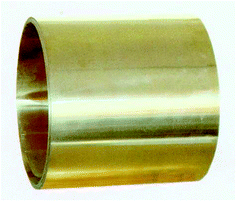
Cementitious materials include 42.5 R ordinary Portland cement, fly ash with specific gravity of 2.05 g cm−3 and silica fume with average particle size 0.1–0.15 mm. A naphthalene-based super-plasticizer with 20% water reducing rate was employed to improve mixture's workability. Porous aggregates include expanded polystyrene (EPS) with particle diameter 2–8 mm and ceramsite with shape coefficient of “globular shape < 1.6”. Basalt fiber with tensile strength 4150–4800 MPa was used as the reinforcing materials. As shown in Fig. 1, H63 (C2720) brass strip with thickness 1 mm, tensile strength 350–470 MPa and elongation at break 30% was used as the wrapping materials.The optimum packing density of a particle system, which has a great influence on system's mechanical properties, can be obtained according to dense packing theory.17 Based on dense packing theory, the optimal mixture ratio of BECC can be presented in every 1 m3 with 386 kg cement, 213.5 kg fly ash, 29.7 kg silica fume, 5.9 kg super-plasticizer, 188.7 kg water, 5.3 kg basalt fiber, 362 kg ceramsite, 2.5 kg EPS and 5.21 kg basalt fiber.
2.2 Specimen preparation methods
A 60 L forced mixer was employed to prepare specimens. The preparation methods were designed as follows. Ceramsite and basalt fiber were firstly added and mixed for 120 s. Meanwhile, the basalt fiber was manually added to achieve uniform distribution during the mixing procedure. Then, EPS were added and mixed for 30 s. Later, all the cementitious materials were added and mixed for 60 s. At last, the water super-plasticizer mixture were added and mixed for another 120 s. After the mixing, the mixtures were poured into moulds, which were vibrated for 120 s. The specimens were demoulded 24 hours after casting and were cured in an environmentally-controlled room under 20 degrees centigrade and 95% relative humidity for 28 days. They were cut with two ends smooth and parallel to produce 50 mm-long and 99 mm-diameter cylindrical for SHPB experiments, and 150 mm-length standard cube for quasi-static experiments. In the end, a piece of brass strip was wrapped around the cylindrical specimen for SHPB test and two groups of wire were tied at both ends of brass strip in case of tearing (make sure the wire stick to brass strip tightly).2.3 Compression experiments
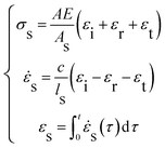
Dynamic compression experiments were conducted by a Φ 100 SHPB system, which was is shown in Fig. 2. Main body mainly includes striker bar, input bar, output bar, damping bar and shock absorber. Energy source mainly includes gas tank. Measuring system mainly includes strain rate and velocity measuring device. The input bar, output bar and damping bar share the same standard as they are made 48 CrMoA, Poisson's ratio is 0.25–0.3, elastic modulus is 210 GPa and density is 7850 kg m−3.When the striker bar is pulsed by high pressure gas, it will strike the input bar with high velocity from the gas tank. Then, an elastic stress wave will propagate through the input bar. The specimen placed between the input bar and output bar is compressed. The incident pulse (εi); reflected pulse (εr) and transmitted pulse (εt) are measured by the strain gauges mounted on the bar. Based on one dimensional wave propagation theory, the strain rate (![[small epsi, Greek, dot above]](https://www.rsc.org/images/entities/i_char_e0a1.gif) s), stress (σs) and strain (εs) are calculated in eqn (1).
s), stress (σs) and strain (εs) are calculated in eqn (1).
 | (1) |
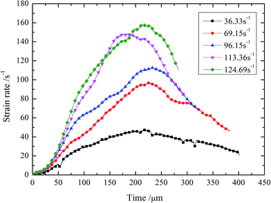
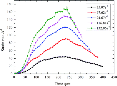
Painting a layer of compound made up with graphite and lubricant can eliminate the interface friction.18 In addition, copper discs with 1 mm in thickness and 30–50 mm in diameter are used as pulse shapers,19 which are employed to solve the problems of nearly constant-strain rate loading. Fig. 3 and 4 presents the strain rate history. It can be seen that the pulse shaping technique has basically achieved nearly constant strain-rate loading, which could improve the test accuracy and ensure the test validity.
Quasi-static compression experiments were carried out by the improved HYY series electro-hydraulic servo system. The results show that the quasi-static compressive strength of BECC and BECC-B are 12.91 MPa and 13.53 MPa, respectively.
3 Results and discussion
3.1 Stress–strain curves
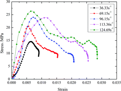
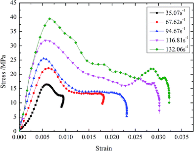
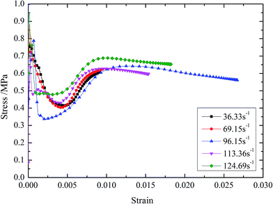
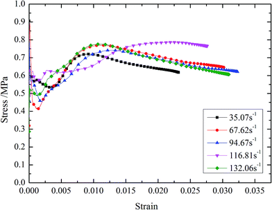
The dynamic stress–strain curves of BECC and BECC-B are shown in Fig. 5 and 6. It can be seen that the stress–strain curves can be generally divided into three periods. (1) Elastic period. The stress showed a linear growth with the strain. The basalt fiber reinforced cement matrix, bearing the main external loadings, generated elastic deformation. (2) Yielding period. When the stress reached the peak value, the specimen began to lose its strength, but it entered into a yielding plateau stage after a certain degree of stress declining. Then, the stress kept in a certain level while the strain increased very much. External loadings energy was mainly absorbed in this period. The stress corresponding to yielding plateau stage increases with strain rate. It was resulted by two effects:20 micro inertia effects and gas effects. When the pore structure collapsed, the local strain rate was greater than the whole one. It caused higher stress in the collision of pore wall. The gas in pore was compressed by the collapsing wall. As a result, the materials stress can be further improved by the high pressure gas. These two effects became more obvious with the increasing of strain rate. (3) Declining period. In this period, external loadings ended and stress decreased sharply. The energy accumulated in composite was liberated. When strain rate was below 69.15 s−1, there was a rebound phenomenon in BECC, namely, stress and strain decreased at the same time. The impulse energy was too weak to damage specimen and the elastic deformation accumulated in elastic period sprang back. BECC-B shared the same law when strain rate was below 67.62 s−1.The stress–strain curves of BECC and BECC-B are similar, but also different slightly. Under the same strain rate, the yielding period of BECC-B is more obvious than that of BECC. This phenomenon gives the credit to the wrappage of brass strip. Radial expansion occured when the pore structure was subjected to impulse loadings. The brass strip, with radial expansion, produced large plastic deformation and didn't break. The yielding period of BECC-B was longer. Another observation is that the stress–strain curve of BECC in Fig. 5 (at 113.36 s−1) shows a different behavior in the elastic period as well as in the yielding period compared to the others. The possible reason for this phenomenon is the discreteness and nonlinearity of concrete material. Above all, the wrapping with brass strip can increase material's plasticity.
3.2 Strength properties
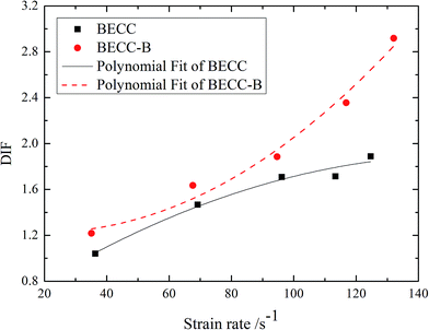
For a better analysis of concrete strength properties, this paper introduced an concept of dynamic increase factor (DIF) of compressive strength, which was defined as the ratio of dynamic compressive strength fc,d to the quasi-static compressive strength fc,s. It is shown in eqn (2). According to the results in Fig. 5 and 6, the relationship between DIF and average strain rate![[small epsi, Greek, dot above]](https://www.rsc.org/images/entities/i_char_e0a1.gif) are shown in Fig. 7.
are shown in Fig. 7.
 | (2) |
According to Fig. 7, the relationships can be expressed as the empirical formulas shown in eqn (3) and (4) through a nonlinear fitting procedure.
BECM: DIF = 0.452 + 0.0186![[small epsi, Greek, dot above]](https://www.rsc.org/images/entities/i_char_e0a1.gif) − 5.936 × 10⁻⁵ − 5.936 × 10⁻⁵![[small epsi, Greek, dot above]](https://www.rsc.org/images/entities/i_char_e0a1.gif) 2, (R2 = 0.958) 2, (R2 = 0.958)
| (3) |
BECM-B: DIF = 1.280 + 0.00520![[small epsi, Greek, dot above]](https://www.rsc.org/images/entities/i_char_e0a1.gif) − 1.294 × 10⁻⁴ − 1.294 × 10⁻⁴![[small epsi, Greek, dot above]](https://www.rsc.org/images/entities/i_char_e0a1.gif) 2, (R2 = 0.965) 2, (R2 = 0.965)
| (4) |
It is obvious that the DIF of BECC and BECC-B increase continuously with average strain rate. The DIF of BECC at 124.69 s−1 is 1.82 times of that at 36.33 s−1. The DIF of BECC-B at 132.06 s−1 is 2.40 times of that at 35.07 s−1. The failure of concrete materials was resulted from the formation and expansion of micro cracks. When the strain rate was relatively low, the concrete failure was contributed to the development of original micro cracks. The development of original cracks need a certain time. The time for the development of original cracks would become less as the strain rate increased. When the strain rate was relatively high, the original cracks didn't have enough time to develop. As a result, the high inner stress forced the concrete matrix to form new cracks. It needed much more energy to produce new cracks than to develop cracks. Consequently, the stress would become larger according to the theory of theorem of impulse.21 The higher the strain rate is, the larger the compressive strength is. Therefore, DIF increases continuously with the strain rate.
The DIF of BECC-B is larger than that of BECC under the same strain rate. This trend is more evident with the increase of strain rate. The DIF of BECC-B is 1.17 times of that of BECC when the strain rate is around 35 s−1. When the strain rate increases to 130 s−1, the times also increases to 1.54. This phenomenon was contributed to the radial constraint of brass strip. When the specimen was under compression, the longitudinal deformation occurred along the loading direction. Meanwhile, the lateral expansion also occurred in specimen due to the effect of Poisson's ratio. Then, the brass strip wrapping around BECC-B would restrain the development of lateral expansion in specimen. Consequently, the development of inner micro cracks were delayed. When the strain rate was higher, more new cracks produced in specimen. Owing to the constraints of brass strip, these new cracks developed gradually. As for the specimens of BECC without radial constraint, a large amount of new cracks were intertwined with each other and developed faster relatively. So, compared with DIF of BECC, the increasing amplification of DIF of BECC-B is larger with the increase of strain rate.
3.3 Deformation properties
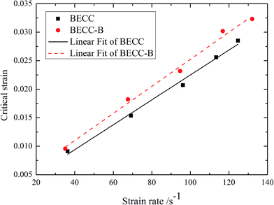
To better understand the deformation properties of concrete materials, this paper introduced a concept of critical strain (εmax), which was defined as the strain corresponding to the failure of concrete. By analysing the results in Fig. 5 and 6, the curves of critical strain with average strain rate were obtained, just as shown in Fig. 8. The relationship between critical strain and average strain rate can be expressed as the empirical formulas in eqn (5) and (6).
BECC: εmax = 6.448 × 10⁻⁴ + 2.185 × 10⁻⁴![[small epsi, Greek, dot above]](https://www.rsc.org/images/entities/i_char_e0a1.gif) , R2 = 0.991 , R2 = 0.991
| (5) |
BECC-B: εmax = 0.00151 + 2.373 × 10⁻⁴![[small epsi, Greek, dot above]](https://www.rsc.org/images/entities/i_char_e0a1.gif) , R2 = 0.991 , R2 = 0.991
| (6) |
It is obvious that the critical strain of BECC and BECC-B increase linearly with average strain rate. When the strain rate increases from 36.33 s−1 to 124.69 s−1, the critical strain of BECC increases 3.13 times. When the strain rate increases from 35.07 s−1 to 132.06 s−1, the critical strain of BECC increases 3.38 times. There are lots of beehive-like micro-holes insider porous materials. These micro-holes yield and collapse under the impact loading. According to the analysis of strength properties, the higher the strain rate is, the larger the compressive strength is. Under the high compressive strength, the micro-holes in specimen deform more fully. More new cracks also form in concrete matrix with the increase of strain rate. The formation and expansion of new cracks could result in more micro-holes to yield and collapse. Under the effect of external loading, the unstable cracks in specimen developed into a damage zone.22 The failure cracks always form in this zone. However, the formation and expansion of new cracks could absorb much energy, which delayed the development of unstable cracks. So the specimen was softened and the critical strain increased. The critical strain of BECC-B was larger than BECC under the same strain rate. The brass strip wrapping around BECC-B imposed radial constraints which restrained the development of cracks. This effect delayed the development of unstable cracks to be further. Therefore, the critical strain of BECC-B became larger relative to BECC.
3.4 Failure patterns
The facture patterns of BECC and BECC-B are shown in Fig. 9 and 10. It can be seen that all specimens are more seriously damaged with the increase of stain rate. As the strain rate increasing, the facture patterns of specimens can be listed as the following: unbroken, edge crack, edge broken, totally broken and totally crushing. When the strain rate was relatively low, the external loading energy was too small to break up specimens. So the facture patterns showed to be unbroken. The external loading energy became larger as the strain rate increased. Because constraint to the middle part concrete was larger than that to the edge part, the edge part concrete broken up firstly. So the facture patterns turned to be edge crack and edge broken. When the energy was large enough to break up the middle part of specimens, the facture patterns turned to be totally broken and totally crushing.Comparing the facture patterns in Fig. 9 and 10, we can see that BECC-B is more seriously damaged than BECC under the same strain rate except for the first sample at 35.07 s−1. The failure of concrete always takes place in the zone of unstable cracks. Under the effect of external loading, a certain amount of new cracks also formed in specimens. On the one hand, the constraints from the brass strip restrained the development of unstable cracks in BECC-B. The delay of concrete failure make more new cracks develop into unstable cracks. However in BECC, less new cracks developed into unstable cracks because of no radial constraints. On the other hand, the radial constraints also made more new cracks form in specimens. So the damage degree is more serious in BECC-B under the same strain rate, which also reflects that BECC-B has a better energy absorbing performance than BECC.
As shown in Fig. 9 and 10, another interesting observation is that the first sample of BECC-B is unbroken while that of BECC is edge crack, which is different from the others. The reason for this phenomenon is discussed as follows. According to the research of damage mechanics,23 the material is subjected to failure only when the energy absorbed by it exceeds its critical value. On the surface, the sample of BECC is edge crack and that of BECC-B is unbroken, indicating that the energy absorbed by BECC exceeds its critical value while the energy absorbed by BECC-B doesn't. As a result, BECC-B has a better energy absorbing performance than BECC.
3.5 Energy absorbing properties
A yielding plateau stage will form in the compression of porous materials. The external loading energy will be converted into irreversible deformation energy by squeezing the pore structure, such as brittle destruction, plastic failure, fragment friction and thermal energy. Then, the goal of absorbing energy and buffering external loadings will be achieved. J. Miltz24 put forward ideal energy absorbing efficiency in the study of foamed aluminum for properly evaluating the energy absorbing performance. Ideal energy absorbing efficiency is defined as the ratio of energy absorbed by actual materials to that absorbed by ideal materials. It's shown in eqn (7).
 | (7) |
Eqn (7) can be well applied to evaluate the energy absorbing performance of foamed aluminum, while it is not suitable for BECC-B and BECC. Their stress don't go up all the way, but fall up to a certain degree and then enter into plateau stage. Consequently, eqn (7) was developed into eqn (8).
 | (8) |
In reality, eqn (8) is the common form of eqn (7). The ideal energy absorption efficiency curves of BECC and BECC-B were calculated according to their stress–strain curves, just as shown in Fig. 11 and 12. Under different strain rate, the average ideal energy absorption efficiency of BECC varies from 55.1% to 63.2%, while that of BECC-B varies from 58.5% to 73.3%. It is obvious that BECC-B wrapped with brass strip have a better energy absorption performance than BECC. BECC itself have a certain energy absorption performance. The pore structure in BECC formed a yielding plateau stage in the compression. External loadings energy was mainly absorbed in this plastic deformation. The brass strip, with excellent toughness, produced large plastic deformation and didn't break. As a result, the plastic deformation was extended and more energy was absorbed. So BECC-B wrapped with brass strip has a better energy absorption performance. With the scope of the study the effects of strain rate on ideal energy absorption efficiency are not obvious.
BECC-B is a promising energy-absorbing material. Wrapping with brass strip can greatly improve its energy absorption performance. The wrapping is easy and simple to make. With advantages of low density, low cost, high toughness and excellent energy absorption performance, BECC-B has a vast prospect to be used as the distribution layers in defensive engineering.
4 Conclusions
A Φ 100 mm SHPB system was employed to conduct dynamic compression experiments. The stress–strain curves of BECC and BECC-B were systematically analyzed. The mechanical properties, including strength properties, deformation properties and failure patterns, were analyzed. Based on these, the energy absorbing properties were also analyzed.The stress–strain curves can be divided into three periods: elastic period, plateau period and declining period. The plateau stress increases with strain rate. The plateau period of BECC-B is more evident than that of BECC under the same strain rate. The mechanical properties of BECC-B are more sensitive to strain rate than that of BECC. The facture patterns of specimens can be listed as the following: unbroken, edge crack, edge broken, totally broken and totally crushing. BECC-B is more seriously damaged than BECC under the same strain rate. The specimens after being wrapped with brass strip have higher ideal energy absorption efficiency. It suggests that BECC-B has a better energy-absorbing performance than BECC. To sum up, BECC-B is a promising energy-absorbing material, which can be used as the distribution layers in defensive engineering.
Acknowledgements
We gratefully acknowledge financial support from Projects of National Natural Science Foundation of China (51208507, 51378497).References
- L. B. Jayasinghe, D. P. Thambiratnam and N. Perera, et al., Blast response and failure analysis of pile foundations subjected to surface explosion, Eng. Failure Anal., 2014, 39(4), 41–54 CrossRef.
- C. G. Zang, X. D. Zhu and Q. J. Jiao, Study of New Materials Design and Application for Multi-functional Munitions Packaging, Packag. Eng., 2011, 32(23), 46–49 CAS.
- X. Yu, X. Chen and W. Zhao, et al., The Influence of an EPS Concrete Buffer Layer Thickness on Debris Dams Impacted by Massive Stones in the Debris Flow, Shock Vib., 2015, 2015(4), 1–11 Search PubMed.
- S. Q. Xu, Study on the characteristics, preparation and application of porous materials, Vaccine, 2015, 20(Suppl. 2), S36–S43 Search PubMed.
- W. J. Roth, B. Gil and W. Makowski, et al., Layer like porous materials with hierarchical structure, Adv. Mater., 2015, 23(22–23), 2602–2615 Search PubMed.
- R. Dou, S. Qiu and Y. Ju, Simulation of Effect of Loading Rate on Compression Properties in the Two-Dimensional Model of Aluminum Foam Sandwich Panels, Mater. Trans., 2016, 57(2), 99–102 CrossRef CAS.
- H. Wisniewski and L. Plonecki, The dynamic properties of the IPMC polymer, Carpathian Control Conference (ICCC), 2015 16th International. IEEE, 2015, pp. 555–580 Search PubMed.
- X. Luo, J. Y. Xu and W. M. Li, Basalt fiber reinforced porous aggregates-geopolymer based cellular material, Funct. Mater. Lett., 2015, 08(1), 1–4 CrossRef.
- A. Khademi and H. Sar, Comparison of Sulfur Concrete, Cement Concrete and Cement-Sulfur Concrete and their Properties and Application, Curr. World Environ., 2015, 10(1), 201–207 CrossRef.
- V. S. Kumar and G. Manikandaraja, Numerical study on energy absorbing characteristics of thin-walled tube under axial and oblique impact, Alexandria Eng. J., 2016, 55(1), 187–192 CrossRef.
- T. Umeda, T. Yamaguchi and K. Mizushiri, et al., Energy Absorption Due to Quasi-Static, Low-Speed and Impact Oblique Crushing of Thin-Walled Tube Structure, J. Soc. Mater. Sci., Jpn., 2015, 64(10), 806–813 CrossRef CAS.
- A. Moradpour, M. Elyasi and S. Montazeri, Developing a New Thin-Walled Tube Structure and Analyzing its Crushing Performance for AA 60601 and Mild Steel Under Axial Loading, Trans. Indian Inst. Met., 2015, 1–11 Search PubMed.
- E. Choi, J. W. Kim, I. Rhee and J. W. Kang, Behavior and modeling of confined concrete cylinders in axial compression using FRP rings, Composites, Part B, 2014, 58, 175–184 CrossRef.
- J. A. Abdullah, Z. Sumei and L. Jiepeng, Shear strength and behavior of tubed reinforced and steel reinforced concrete (TRC and TSRC) short columns, Thin Wall. Struct., 2010, 48(3), 191–199 CrossRef.
- F. Zhang and C. L. De, Effect of Applied Tension on Quality of Brass Strip Manufactured by Extrusion Cutting, CIRP Ann. Manuf. Technol., 1987, 36(1), 53–56 CrossRef.
- J. T. Chen, Z. T. Qian and X. J. Zhang, The Way of H65 Brass Strip Performance Control, Copper Eng., 2015, 5, 5–8 Search PubMed.
- H. T. Liu, S. Q. Liu and Q. I. Feng-Zhong, Research Progress of Cement Slurry System Optimized by Dense Packing Theory, Bull. Chin. Ceram. Soc., 2014, 9(33), 2269–2274 Search PubMed.
- Q. M. Li and H. Meng, About the dynamic strength enhancement of concrete-like materials in a split Hopkinson pressure bar test, Int. J. Solids Struct., 2012, 40(2), 343–360 CrossRef.
- D. J. Frew, M. J. Forrestal and W. Chen, Pulse shaping techniques for testing elastic–plastic materials with a split Hopkinson pressure bar, Exp. Mech., 2005, 45(2), 186–195 CrossRef.
- M. Fathalilou, M. Sadeghi and G. Rezazadeh, Micro-inertia effects on the dynamic characteristics of micro-beams considering the couple stress theory, Mech. Res. Commun., 2014, 60, 74–80 CrossRef.
- R. Seliktar, M. Yekutiel and A. Bar, Gait consistency test based on the impulse-momentum theorem, Prosthet. Orthot. Int., 2009, 3(2), 91–98 Search PubMed.
- C. A. Ross, D. M. Jerome, J. W. Tedesco and M. L. Hughes, Moisture and strain rate effects on concrete strength, ACI Mater. J., 1996, 93(3), 293–300 CAS.
- Y. U. Hai-Xiang, W. U. Jian-Hua and L. I. Qiang, A rational method for defining damage variables in one dimension, J. Chongqing Univ., 2008, 31(11), 1261–1266 Search PubMed.
- J. Miltz and G. Gruenbaum, Evaluation of cushioning properties of plastic foams from compressive measurements, Polym. Eng. Sci., 1981, 21(15), 1010–1014 CAS.
| This journal is © The Royal Society of Chemistry 2017 |

