 Open Access Article
Enhanced magnetization in unusual carbon-nanotube/carbon-foam cm-scale hybrid-buckypaper films with high α-Fe filling-ratio†
J. Zhu‡
a,
D. Liu‡a,
J. Wanga,
H. Yib,
S. Wangb,
J. Wenb,
M. A. C. Willisa,
Y. Houa,
J. Borowiec*a and
F. S. Boi *a
*a
aCollege of Physical Science and Technology, Sichuan University, Chengdu CN, China. E-mail: f.boi@scu.edu.cn; borowiec@scu.edu.cn
bAnalytical and Testing Centre, Sichuan University, Chengdu CN, China
First published on 10th April 2017
Abstract
We report the synthesis of novel and unusual α-Fe-filled carbon nanotube (CNT)/carbon foam (CFM) hybrid-buckypaper films via pyrolysis of ferrocene/dichlorobenzene mixtures. The presence of a direct connection between the CFM and the CNT-buckypapers is found to significantly enhance the magnetization properties revealing room temperature saturation magnetizations as high as 73 emu g−1. The magnetic properties of these films are compared to those typical of cm-scale horizontally aligned and randomly oriented Fe3C-filled CNTs buckypapers and to those observed for Fe-filled and Ni-filled CFMs. This finding has a great significance in the field of ferromagnetically filled CNTs, since it implies that the properties of α-Fe-filled CFM can be combined with those of ferromagnetically filled CNTs in a single buckypaper-structure for possible future application as a microwave absorber. The properties of the obtained films are characterized in detail with scanning electron microscopy, transmission electron microscopy, X-ray diffraction, Fourier transform infrared spectroscopy and vibrating sample magnetometry.
Introduction
In the last decade carbon based materials like carbon nanotubes (CNTs), graphite and graphene have attracted great attention thanks to their outstanding physical, chemical and electronic properties.1–4 Several approaches have been reported in the fabrication of CNT paper and film structures. For example, CNTs have been generally fabricated in the form of films with high vertical alignment through chemical vapour deposition (CVD) experiments involving the pyrolysis of organometallic precursors (i.e. ferrocene)5–13 or pyrolysis of mixtures of organometallics with benzene-based precursors.14–17 On the other hand, the use of Cl-based liquid precursors (i.e. chlorobenzene, dichlorobenzene, trichlorobenzene) mixed with ferrocene has also been reported for the synthesis of randomly oriented entangled CNTs films (also known as buckypapers) partially filled with ferromagnetic crystals.18–23 Alternatively, the addition of small quantities of sulfur to ferrocene has been considered for the synthesis of hollow single walled (SW) CNTs or thin walled CNTs buckypapers.24–26 In addition, elastic buckypaper membranes have been fabricated also for the case of very low concentrations of Cl radicals to achieve high ferromagnetic filling ratios and high ferromagnet-crystallinity.27,28 Specifically the concentration of Cl radicals has been reported to strongly affect the alignment of the synthesised CNTs leading to either random orientation in the horizontal plane under conditions of low vapour flow rates (10–20 ml min−1) or to horizontal alignment under conditions of high vapour flow rates (100 ml min−1).28,29 Other methods of buckypaper fabrication have also been proposed, such as the domino method and filtration methods.30,31 In filtration-based approaches the use of specific solvents or surfactants has been proposed for the buckypaper preparation.31 In addition to bucky papers, other types of CNTs-film morphologies known as aerogels have been the subject of great interest owing to their ultra-light weight and highly porous nature.32 The methods for production of CNT-aerogels differ significantly from the vertically aligned CNT and buckypaper cases. CNT aerogels are indeed generally fabricated through chemical methods by subjecting a wet-gel precursor to critical-point drying or lyophilization (freeze-drying).32 Ultralight CNT aerogels with a density of 4 mg cm−3 have also been reported in 2010, produced from a wet gel of well-dispersed pristine MWCNTs. Such ultralight CNT aerogel structures were found to have an ordered macroporous honeycomb structure.33 In this type of material surface areas of 580 m2 g−1 have been reported, which are much higher than those measured in the case of pristine multiwall CNTs (241 m2 g−1)33 but lower than those measured in empty SWCNTs buckypapers (300–950 m2 g−1).34 Alternatively to the CNTs-film and aerogel cases is another type of carbon material, known as carbon foam (CFM), which has attracted much attention owing to its ultralow and tuneable density (1–1000 mg cm−3).35 Recent work has also shown that in some cases CFM morphologies can be filled with continuous quantities of ferromagnetic α-Fe, giving rise to giant magnetizations properties.36In this work we report the synthesis of novel and unusual α-Fe-filled CNT/CFM hybrid-buckypaper films using pyrolysis of ferrocene/dichlorobenzene mixtures on Si/SiO2 substrates. The presence of a direct connection between the Fe–CFM and the buckypapers is found to significantly enhance the magnetization properties of the films revealing room temperature saturation magnetizations as high as 73 emu g−1. The magnetic properties of these films are compared to those typical of large scale (i.e. many cm-scale) horizontally aligned and randomly oriented Fe3C-filled CNTs buckypapers, as well as those observed for Fe-filled, Ni-filled and Co-filled CFMs. This finding has great significance in the field of ferromagnetically filled CNTs since it implies that the properties of α-Fe-filled CFM can be combined with those of ferromagnetically filled CNT, in a single buckypaper-structure, for future applications in the design of microwave absorbers. The observed high filling-ratio of the nanotubes is demonstrated in detail through scanning electron microscopy (SEM) analyses and cross-sectional transmission electron microscopy (TEM) analyses. The structural arrangement of the films is then investigated through the use of X-ray diffraction (XRD) and Fourier transform infrared spectroscopy (FT-IR) analyses.
Experimental
The method used for the production of the hybrid CNT/CFM buckypaper can be described as follows: mixtures of dichlorobenzene (0.75 ml) and ferrocene (1 gram) were evaporated and pyrolyzed in a CVD system comprising of a quartz-tube reactor of 1.5 m (inner diameter of 44 mm, wall thickness of 3 mm), smooth Si/SiO2 substrates with a 111 preferential crystal orientation (SiO2 thickness in the order of 90 nm and substrate dimensions of 6 cm length, 2.5 cm width and 0.525 mm thickness) and a tube furnace set at 990 °C. Note that the substrates were positioned in the region of the reactor at a temperature of approximately 750–820 °C during the reaction stage (much lower than the 900 °C used for the growth of CNTs buckypapers). The evaporation temperature of approximately 150–160 °C used in these reactions is higher with respect to that used in previous work on buckypapers grown in presence of similar dichlorobenzene quantities28 (120 °C or lower). An Ar flow rate of 11 ml min−1 is used in the reaction to deliver the ferrocene and dichlorobenzene species to the reaction zone. The duration of the reaction was of 2 hours. The obtained samples were cooled down by removing the furnace along a rail system (quench). The hybrid-buckypapers were then peeled off from the Si/SiO2 substrates and washed in distillate water. In order to compare the properties of the hybrid buckypaper films with those of ferromagnetically filled CFM, other experiments were performed for the formation of Fe-filled, Ni-filled and Co-filled CFM samples. The first type of foam was produced following the method of Boi et al. in presence of 0.65 ml of dichlorobenzene.36 The second type of foam was instead produced by evaporation (temperature of 150 °C) and pyrolysis of 1 g of nickelocene at 750–820 °C, with an Ar flow rate of 11 ml min−1. Differently, the third type of foam was produced by direct sublimation and pyrolysis of cobaltocene at 900 °C, with an Ar flow rate of 11 ml min−1. SEM and backscattered electrons investigations were performed with a JSM-7500F at 10–20 kV. TEM was performed with a 300 kV American FEI Tecnai F30. XRD analyses were performed with an Empyrean Panalytical diffractometer (Cu K-α with λ = 0.154 nm). The magnetic properties were investigated through VSM at room temperature with a VSM Quantum Design. The Raman spectra were investigated with a triple grating monochromator (Andor Shamrock SR-303i-B, EU) equipped with an EMCCD (ANDOR Newton DU970P-UVB, EU). A solid-state laser at 532 nm (RGB laser system, NovaPro 300 mW, Germany) and collection by a 100×, 0.90 NA objective (Olympus, Japan) were used. The Raman system was calibrated using the band at 520 cm−1 of a silicon wafer with an error of 0.5 cm−1. FT-IR measurements were performed with a Nicolet 6700 in air at room temperature.Result and discussion
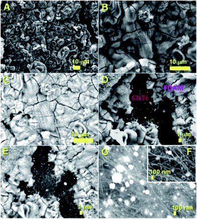
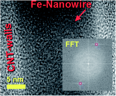
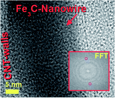
The decomposition mechanism of the ferrocene precursor is often explained via a high temperature exothermic process which leads to the formation of Fe + H2 + CH4 + C5H6 + … species that react to form the metal-particles from which the CNTs and single-crystal filling will grow simultaneously.36,40 In this type of mechanism the Cl radicals play a fundamental role since they can enhance the carbon nanotubes filling rates through the formation of the CCl4 species. These species can remove carbon feedstock from the pyrolyzing vapour and consequently slow down the CNT growth and filling processes by chemically etching the catalyst surface.28 Also, in the presence of very high concentrations of Cl radicals, the formation of metal chlorides has been reported.28 In contrast to the CNT case, the CFM formation mechanism has been reported to be favoured in conditions of relatively low pyrolysis temperatures of the ferrocene/dichlorobenzene precursors. This is due to the lower quantity of carbon and very high concentration of iron achievable during the pyrolysis process.36 In light of the chemical mechanism described above, the formation of the novel buckypapers morphologies reported in this work can be attributed to the interplay of numerous parameters; namely Cl-concentration, Ar-flow rate, evaporation temperature of the precursors and the local-pyrolysis temperature. The evaporation temperature of 150–60 °C together with the quantity of dichlorobenzene used (0.75 ml) were chosen in the attempt to remove large quantities of carbon from the pyrolysis region and induce the formation of α-Fe filled amorphous CFM in the first stages of the reaction. In this manner a pyrolysis temperature of 750–820 °C was chosen, which is slightly higher than that used by Boi et al. for the growth of iron filled CFM36 but can guarantee a low% of carbon since the temperature is too low to induce the complete pyrolysis of ferrocene (i.e. a high concentration of catalyst will be present in this chosen area of the reactor).36 Thus the concentration of carbon is therefore expected to be very low in the first stages of the reaction, given the presence of Cl-radicals, favouring the foam-formation. Meanwhile the buckypaper formation can be considered a consequence of a second reaction-stage in which the Cl-radicals are completely consumed, leading to an increase of the carbon concentration. The buckypaper film is therefore expected to lift-up the Fe-filled amorphous CFM film through a lift-up mechanism similar to those reported in literature.37,38 Note that the use of higher evaporation temperatures led to a disappearance of the buckypaper morphology and the formation of only amorphous CFM structures similar to those observed by Boi et al. with high concentrations of Cl radicals.36 A disappearance of these morphologies is instead observed for high pyrolysis temperatures due to an increase in the concentration of Cl radicals and consequently the formation of amorphous carbon and metal chlorides species.The morphology of the hybrid CNT/CFM buckypaper films was firstly revealed using SEM. The top-side of the film is shown in Fig. 1. In Fig. 1A and B a micrometre-thick layer of CFM is found to completely cover the buckypaper on the top-side. The expected high metal content of CFM was investigated by the use of backscattered electrons (B.E.). BE analyses are very sensitive to atomic number differences and are consequently frequently used for imaging the contrast between metal phases. As shown in Fig. 1C, these analyses revealed the presence of extremely high and continuous metal filling ratios within the foam (bright areas). The surface of the foam appears to exhibit unusual cracks which may have been induced by the SEM-sample preparation. The fact that these cracks are observed suggests that the structure of this type of CFM-film may not have a high degree of flexibility. Interestingly, as shown in Fig. 1D and E SEM and BE imaging in the regions of the CFM-cracks clearly reveals a direct interfacial contact between the CFM and the buckypaper. Note that specifically a direct connection between the Fe–CFM and the buckypaper was clearly observed in these interfacial regions (see Fig. 1D and E). The morphology of the CNTs at the interface was revealed under high magnification of the buckypaper interface. In Fig. 1F and G the observed CNTs are found to contain high metal filling ratios. Similar results were also obtained from images taken in the bottom-regions of the buckypaper, as shown in Fig. 2A and B. Note that also in this case the presence of high filling ratios was revealed by BE analyses. In order to further verify the filling-ratio of the CNTs within the buckypaper the use of TEM was then considered. Typical micrographs showing the CNTs cross-sectional morphology are shown in Fig. 2C–F. These micrographs confirm the presence of high filling ratios within the CNTs capillaries. This interpretation was also confirmed by the high resolution TEM analyses of the Fe-based nanowires shown in Fig. 3 and 4 (see also ESI Fig. 3† for more cross-sectional TEM examples of the CNTs comprised in the buckypaper). The scanning TEM images of the foam/CNTs connection and foam-side compositional analyses are shown in ESI Fig. 4–6.† The observed CNTs-diameter was in the order of 40–50 nm. Further structural analyses were then carried out with XRD. The analyses performed on both the sides of the buckypaper-hybrid films are shown in ESI Fig. 1 and 2.† The analyses performed on the top-side (CFM-side) of the buckypaper-hybrid film revealed the presence of a single peak corresponding to the 110 reflection of α-Fe. Similarly, also in the case of the back side of the buckypaper, the presence of an intense 110 reflection of α-Fe was found together with other Fe3C reflections with lower intensity (ESI Fig. 2A†). The quantity of α-Fe and Fe3C in the CNTs were quantified using the Rietveld refinement method as shown in ESI Fig. 2B.† Note that the use of thermogravimetric (TGA) analyses was not considered since there is no means to distinguish the Fe3C phase from the α-Fe phase within the buckypaper. Most notably the Rietveld refinement revealed the presence of 85% of graphitic carbon, together with 6.35% of Fe3C and 8.65% of α-Fe. Rescaling the relative abundances with respect to the only ferromagnetic components it yields 42.3% of Fe3C and 57.7% of α-Fe. In addition, the following unit cell parameters were extracted. For α-Fe: a = b = c: 0.2859 nm, for Fe3C a: 0.5092 nm, b: 0.6741 nm and c: 0.4527 nm. The extracted graphitic unit cell of the CNTs was as follow: a = b: 0.2470 nm and c: 0.6800 nm.
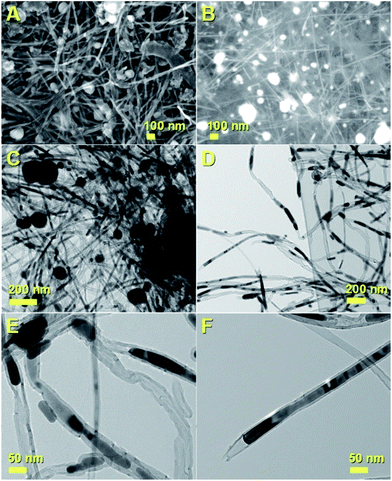 | ||
| Fig. 2 SEM micrographs showing the lower-side (opposite-side with respect to Fig. 1) region of the α-Fe-filled CNT/CFM hybrid-buckypaper films obtained by pyrolysis of ferrocene/dichlorobenzene mixtures with secondary electrons (in A) and BE (in B) imaging. Note that backscattered electron allows visualizing the atomic contrast in the sample, therefore the Fe-containing areas will appear bright in the image, while carbon will appear with a grey-like colour. The TEM analyses of the CNTs comprised within the buckypaper are shown in (C–F). The CNTs exhibit high filling rates. | ||
Differently, as shown by the XRD diffractogram in ESI Fig. 1,† only α-Fe is found within the CFM side of the hybrid buckypaper sample (110 reflection). For typical examples of Fe-content quantification within the only Fe-filled CFM measured with TGA see ref. 36. The presence of thin walls in the CNTs structure was also confirmed by the observation of the 002 reflection of graphite in the region of 26 degrees 2θ.
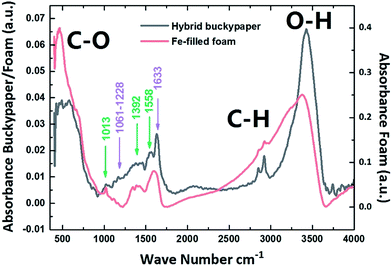
The structural properties of the buckypaper-hybrid films were then examined using FT-IR and compared to those of amorphous CFM continuously filled with α-Fe. The result of these measurements is shown in Fig. 5. These analyses revealed the presence of similar absorbance peaks in the regions of 1013 cm−1, 1392 cm−1 and 1558 cm−1 (see green arrows) for both the hybrid-buckypaper and the Fe-filled CFM-case. These measurements confirm the presence of CFM in our sample. In addition, the presence of CNTs within the buckypaper was confirmed by the observation of other absorbance peaks in the region of 1061–1228 cm−1 and of 1633 cm−1 (magenta-arrows). These can be assigned to the D band and G band respectively.41–43 In addition, the bands at approximately 1300 cm−1 and 1500 cm−1 can be attributed to the coexistence of sp2 and sp3 hybridization in the foam structure. In particular to a mixed sp2–sp3 C–C vibration mode and have been generally reported at 1250 cm−1 and 1515 cm−1.44 An un-assigned peak is also found in the region of approximately 1000 cm−1 and appears to be present in both the hybrid buckypaper and the pure foam sample.
Further analyses were then performed on the foam films produced by pyrolysis of nickelocene and cobaltocene. The first type of films (obtained by pyrolysis of nickelocene) were found to be characterized by a graphitic structure with unusual cages as shown in ESI Fig. 7A–F† and by a high metal content, as demonstrated by the BE analyses in ESI Fig. 7† and scanning TEM analyses in ESI Fig. 8D.† The structural analyses of this kind of foam, performed using XRD, Raman and FT-IR, are shown in ESI Fig. 8.† Similar structural and morphological characteristics were found also for other type of porous carbon-foam samples filled with Co produced by pyrolysis of cobaltocene (see ESI Fig. 9 and 10†). Also in this case the structural arrangement of the foam was analysed by SEM, EDX, FTIR (ESI Fig. 9†) and XRD (ESI Fig. 10†). The comparison between the magnetic properties of the hybrid-buckypaper films and those of the Fe-filled, Ni-filled and Co-filled CFM films was then considered through room temperature VSM measurements. Interestingly, as shown in Fig. 6 saturations magnetizations as high as 73 emu g−1 (black hysteresis) were found for the case of the hybrid buckypaper. These are much higher with respect to those recently reported in the case of cm-scale (i.e. many cm scale) buckypapers filled with Fe3C (i.e. 58.7 emu g−1).21,28 The observed saturation magnetization is also higher with respect to that recently reported in the case of other type of buckypaper morphologies filled with α-Fe39 and with respect to that reported by R. Lv et al. in the case of FeNi and FeCo filled CNTs.20,23
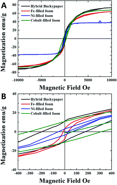 | ||
| Fig. 6 VSM analyses at room temperature of the hybrid-buckypaper (black) and Fe-filled (red), Ni-filled (blue) and Co-filled (green) foam-films. | ||
The presence of such a high value of magnetization can be associated to the large quantity of α-Fe present within the carbon foam which strongly enhances the magnetization properties of the ferromagnetically filled buckypaper. Indeed the saturation magnetization of CNTs is expected to increase with the increase of the quantity of encapsulated Fe-based material. Note also that the absence of iron-oxide by-products makes this material suitable for numerous applications in microwave absorption and electrodes for data recording devices. The measured saturation magnetization is also much higher with respect to that measured for the Fe-filled CFM films (red hysteresis in Fig. 6, saturation magnetization of 63 emu g−1) produced with ferrocene–dichlorobenzene mixtures (with comparable concentration of dichlorobenzene of 0.65 ml) and with respect to that measured in the case of the Ni-filled CFM and Co-filled CFM (blue and green hysteresis in Fig. 6, saturation magnetizations of 37 emu g−1 and 67 emu g−1 respectively). The magnetization properties are however lower with respect to those of the Fe-filled foam-films (200–220 emu g−1) produced by pyrolysis of ferrocene with lower quantities of dichlorobenzene (0.15 ml).36 On the other hand, the measured coercivity of 200 Oe is lower with respect to those measured in previous reports on large scale (many cm-scale) buckypapers filled with Fe3C.21,28 Note that in the case of the CFM-samples filled with Fe and Ni, much lower values of coercivity in the order of 11 Oe (Fe-filled CFM) and 55 Oe (Ni-filled CFM) were found. Instead coercivities in the order of 300 Oe were found in the case of CFM samples filled with Co (green hysteresis).
Conclusion
In conclusion we reported the synthesis of novel and unusual α-Fe-filled CNT/CFM hybrid-buckypaper films by pyrolysis experiments of ferrocene/dichlorobenzene mixtures. The presence of a direct connection between the Fe-filled CFM and the Fe-filled-CNTs buckypapers is found to significantly enhance the magnetization properties of the hybrid-films revealing room temperature saturation magnetizations as high as 73 emu g−1. The magnetic properties of these films are compared to those typical of large scale (many cm-scale) horizontally aligned and randomly oriented Fe3C-filled CNTs buckypapers previously reported in literature as well as those observed for Fe-filled, Ni-filled and Co-filled CFMs. The structure of these unusual films is investigated in detail using SEM, TEM, XRD and FT-IR analyses and is compared to that of Fe-filled and Ni-filled CFMs. This finding implies that the properties of α-Fe-filled CFM can be combined with those of ferromagnetically filled CNTs in a single buckypaper-structure for possible future applications as electrodes for magnetic data recording applications or as microwave absorbers.Acknowledgements
We acknowledge the young NSFC 11404227 researcher found, and professor Gong Min for his continuous support to this research project. We also acknowledge professor Lei Li for the help in the Raman measurements.Notes and references
- S. Iijima, Nature, 1991, 354, 56 CrossRef CAS.
- S. Iijima and T. Ichihashi, Nature, 1993, 363, 603 CrossRef CAS.
- K. S. Novoselov, A. K. Geim, S. V. Morozov, D. Jiang, Y. Zhang, S. V. Dubonos, I. V. Grigorieva and A. A. Firsov, Science, 2004, 306, 666–669 CrossRef CAS PubMed.
- J. Guo, M. Lan, Y. He, Y. Hou, X. Zhang, S. Zhang, S. Wang, G. Xiang and F. S. Boi, RSC Adv., 2016, 6, 99960–99968 RSC.
- H. Terrones, F. López-Urías, E. Muñoz-Sandoval, J. A. Rodríguez-Manzo, A. Zamudio and A. L. Elías, et al., Solid State Sci., 2006, 8, 303–320 CrossRef CAS.
- C. Muller, S. Hampel, D. Elefant, K. Biedermann, A. Leonhardt and M. Ritschel, et al., Carbon, 2006, 44, 1746–1753 CrossRef.
- C. Muller, D. Golberg, A. Leonhardt, S. Hampel and B. Buchner, Phys. Status Solidi A, 2006, 203, 1064–1068 CrossRef.
- S. Hampel, A. Leonhardt, D. Selbmann, K. Biedermann, D. Elefant and Ch. Muller, et al., Carbon, 2006, 44, 2316–2322 CrossRef CAS.
- A. Leonhardt, M. Ritschel, M. Elefant, D. N. Mattern, K. Biedermann and S. Hampel, et al., J. Appl. Phys., 2005, 98, 074315 CrossRef.
- A. Leonhardt, M. Ritschel, R. Kozhuharova, A. Graff, T. Muhl and R. Huhle, et al., Diamond Relat. Mater., 2003, 12, 790–793 CrossRef CAS.
- F. S. Boi, S. Maugeri, J. Guo, M. Lan, S. Wang and J. Wen, et al., Appl. Phys. Lett., 2014, 105, 243108 CrossRef.
- F. C. Dillon, A. Bajpai, A. Koos, S. Downes, Z. Aslam and N. Grobert, Carbon, 2012, 50, 3674–3681 CrossRef CAS.
- A. L. Danilyuk, A. L. Prudnikava, I. V. Komissarov, K. I. Yanushkevich, A. Derory and F. Le Normand, et al., Carbon, 2014, 68, 337–345 CrossRef CAS.
- A. Morelos-Gomez, F. Lopez-Urias, E. Munoz-Sandoval, C. L. Dennis, R. D. Shull and H. Terrones, et al., J. Mater. Chem., 2010, 20, 5906 RSC.
- R. Xiang, G. Luo, W. Qian, Q. Zhang, Y. Wang, F. Wei, Q. Li and A. Cao, Adv. Mater., 2007, 19, 2360–2363 CrossRef CAS.
- R. Zhang, Q. Wen, W. Qian, D. S. Su, Q. Zhang and F. Wei, Adv. Mater., 2011, 23, 3387–3391 CrossRef CAS PubMed.
- R. Zhang, Y. Zhang, Q. Zhang, H. Xie, W. Qian and F. Wei, ACS Nano, 2013, 7, 6156–6161 CrossRef CAS PubMed.
- W. Wang, K. Wang, R. Lv, J. Wei, X. Zhang, F. Kang, J. Chang, Q. Shu, Y. Wang and D. Wu, Carbon, 2007, 45, 1127–1129 CrossRef CAS.
- R. Lv, F. Kang, W. Wang, J. Wei, J. Gu, K. Wang and D. Wu, Carbon, 2007, 45, 1433–1438 CrossRef CAS.
- R. Lv, A. Cao, F. Kang, W. Wang, J. Wei and J. Gu, J. Phys. Chem. C, 2007, 111, 11475 CAS.
- R. Lv, S. Tsuge, X. Gui, K. Takai, F. Kang and T. Enoki, et al., Carbon, 2009, 47, 1141–1145 CrossRef CAS.
- X. Gui, K. Wang, W. Wang, J. Wei, X. Zhang and R. Lv, et al., Mater. Chem. Phys., 2009, 113, 634–637 CrossRef CAS.
- R. Lv, F. Kang, J. Gu, X. Gui, J. Wei and K. Wang, et al., Appl. Phys. Lett., 2008, 93, 223105 CrossRef.
- L. Song, L. Ci, L. Lv, Z. Zhou, X. Yan, D. Liu, H. Yuan, Y. Gao, J. Wang, L. Liu, X. Zhao, Z. Zhang, X. Dou, W. Zhou, G. Wang, C. Wang and S. Xie, Adv. Mater., 2004, 16, 1529–1534 CrossRef CAS.
- W. Ma, L. Song, R. Yang, T. Zhang, Y. Zhao, L. Sun, Y. Ren, D. Liu, L. Liu, J. Shen, Z. Zhang, Y. Xiang, W. Zhou and S. Xie, Nano Lett., 2007, 7, 2307–2311 CrossRef CAS PubMed.
- W. Zhou, Q. Fan, Q. Zhang, K. Li, L. Cai, X. Gu, F. Yang, N. Zhang, Z. Xiao, H. Chen, S. Xiao, Y. Wang, H. Liu, W. Zhou and S. Xie, Small, 2016, 12, 3407–3414 CrossRef CAS PubMed.
- J. Guo, M. Lan, S. Wang, Y. He, S. Zhang and G. Xiang, et al., Phys. Chem. Chem. Phys., 2015, 17, 18159–18166 RSC.
- F. S. Boi, J. Guo, S. Wang, Y. He, G. Xiang, X. Zhang and M. Baxendale, Chem. Commun., 2016, 52, 4195–4198 RSC.
- J. Guo, Y. He, S. Wang and F. S. Boi, Carbon, 2016, 102, 372–382 CrossRef CAS.
- D. Wang, P. Song, C. Liu, W. Wu and S. Fan, Nanotechnology, 2008, 19, 075609 CrossRef PubMed.
- M. T. Byrne and Y. K. Gunko, Adv. Mater., 2010, 22, 1672–1688 CrossRef CAS PubMed.
- M. B. Bryning, D. E. Milkie, M. F. Islam, L. A. Hough, J. M. Kikkawa and A. G. Yodh, Adv. Mater., 2007, 19, 661–664 CrossRef CAS.
- J. Zou, J. Liu, A. S. Karakoti, A. Kumar, D. Joung, Q. Li, S. I. Khondaker, S. Seal and L. Zhai, ACS Nano, 2010, 4, 7293–7302 CrossRef CAS PubMed.
- A. A. B. Davijani, H. C. Liu, K. Gupta and S. Kumar, ACS Appl. Mater. Interfaces, 2016, 8, 24918–24923 Search PubMed.
- A. Zani, D. Dellasega, V. Russo and M. Passoni, Carbon, 2013, 56, 358–365 CrossRef CAS.
- F. S. Boi, J. Guo, M. Lan, T. Yu, S. Wang, Y. He, J. Wen and G. Xiang, Carbon, 2016, 101, 28–36 CrossRef CAS.
- X. Li, A. Cao, Y. J. Jung, R. Vajtai and P. M. Ajayan, Nano Lett., 2005, 5, 1997–2000 CrossRef CAS PubMed.
- L. Zhu, D. W. Hess and C.-P. Wong, J. Phys. Chem. B, 2006, 110, 5445–5449 CrossRef CAS PubMed.
- F. S. Boi, Y. Hu, S. Wang and Y. He, RSC Adv., 2016, 6, 69226 RSC.
- U. Weissker, S. Hampel, A. Leonhardt and B. Buchner, Materials, 2010, 3, 4387–4427 CrossRef CAS.
- A. Misra, P. K. Tyagi, P. Rai and D. S. Misra, J. Nanosci. Nanotechnol., 2007, 7, 1820–1823 CrossRef CAS PubMed.
- N. Kouklin, M. Tzolov, D. Straus, A. Yin and J. M. Xu, Appl. Phys. Lett., 2004, 85, 4463–4465 CrossRef CAS.
- D. B. Mawhinney and J. T. Yates Jr, Carbon, 2001, 39, 1167–1173 CrossRef CAS.
- V. Tucureanu, A. Matei and A. M. Avram, Crit. Rev. Anal. Chem., 2016, 46, 502–520 CrossRef CAS PubMed.
Footnotes |
| † Electronic supplementary information (ESI) available. See DOI: 10.1039/c7ra02669b |
| ‡ These authors contributed equally to this work. |
| This journal is © The Royal Society of Chemistry 2017 |

