 Open Access Article
Creative Commons Attribution 3.0 Unported Licence
A PEO-based gel polymer electrolyte for lithium ion batteries†
Wangyu Li,
Ying Pang,
Jingyuan Liu,
Guanghui Liu,
Yonggang Wang and
Yongyao Xia *
*
Department of Chemistry, Shanghai Key Laboratory of Molecular Catalysis and Innovative Materials, Institute of New Energy, Fudan University, Shanghai, 200433, China. E-mail: yyxia@fudan.edu.cn
First published on 28th April 2017
Abstract
A lithium-ion conducting gel polymer electrolyte (GPE) membrane containing PEO as a polymer host and liquid electrolyte has been prepared by a simple one-step procedure. The prepared electrolyte membrane exhibits a good ionic conductivity of 3.3 × 10⁻³ S cm−1 and high lithium transference number of 0.76 at room temperature. Meanwhile, the gel polymer electrolyte membrane shows very good thermal stability. A Li/GPE/LiFeO4 cell was fabricated to demonstrate the electrochemical performance of the GPE. The cell exhibits good cycling stability with a high capacity retention of 81% after 500 cycles and as good a rate performance as LiFeO4 tested in liquid electrolyte.
1. Introduction
The demand for rechargeable lithium-ion batteries has been increasing rapidly over the past several decades with the development of electronic devices, electric vehicles (EV) or hybrid electric vehicles (HEV) and the growing need for storage of new green energy (wind, solar, nuclear, tide energy, biomass, etc.) in smart grids.1–3 However, the commercial application of lithium ion batteries with large capacity and high energy and power density has been limited due to the use of liquid organic electrolytes.4 They suffer from safety problems because of their flammable nature. With liquid electrolytes, batteries can easily catch fire and even be explosive in case of misusage, short circuits or local overheating.5,6 Therefore, it is urgent to develop safer and more reliable electrolyte systems. Polymer electrolytes have been widely studied as a safe and promising alternative to meet the challenges for application in lithium ion batteries during recent years.7–11 In recent years, polymer electrolytes have also shown promising applications in lithium–sulfur and lithium–oxygen batteries.12–17 Polymer electrolyte shows no worry of overheating, electrolyte leakage and fire safety. In addition, polymer electrolyte has more advantages in shape flexibility and manufacture process ability.11,18,19Polymer electrolytes mainly include solid polymer electrolyte and gel polymer electrolyte. For solid polymer electrolytes, it still needs a long way for their industrial application because they have low ionic conductivity at ambient temperature.20–23 Gel Polymer Electrolytes (GPE) have received a lot of attention in recent years as a compromise by possessing the advantages of both solid and liquid electrolytes.24–26 Gel polymer electrolyte is a hybrid system formed by trapping a large amount of liquid electrolyte a lithium ion conducting organic solution in a polymer matrix (e.g. poly(ethylene oxide) (PEO), poly(vinylidene difluoride) (PVdF), polyvinyl chloride (PVC), poly(methyl methacrylate) (PMMA) and poly-(vinylidene fluoride-hexafluoropropylene) (P(VDF-HFP)) copolymer) through physical and chemical methods.27–32 For gel polymer electrolyte, the transfer of lithium-ion mainly depends on the swollen gelled phase or the absorbed liquid electrolyte. By sharing both the beneficial characteristics of solid and liquid electrolyte, gel polymer electrolyte system has advantages of high ionic conductivity, good mechanical strength, better flexibility, wide electrochemical window, good compatibility with electrodes, and an improved trapping capability of liquid electrolytes than conventional separators. In addition, the better thermal stability of the GPE will lead to the improved safety of the lithium ion batteries,33 and the encapsulated liquid electrolyte in a solid polymer host can lead to enhanced electrode/electrolyte interface stability toward both electrodes.34
Normally, the most common preparation methods for the gel polymer involves the preparation of a porous membrane first and then absorb some of the liquid electrolyte.35–37 But the preparation process is a little too difficult to be scaled up for industry use. So an easier synthesis method is needed.
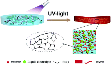
Here, an in situ polymerization method was adopted as a simpler method. PEO was chosen as the polymer matrix which has been studied for decades.38–40 Commercialized lithium (hexafluoro) phosphate (LiPF6) based liquid electrolytes are used as gelling agents. Trimethylolpropane ethoxylate triacrylate was added as the ionomer. After the treatment of UV light, trimethylolpropane ethoxylate triacrylate was polymerized and liquid electrolyte were confined into the solidified framework of the polymer (Scheme 1). The electrochemical properties of the as-prepared gel polymer electrolyte have been evaluated by the study of its ionic conductivity, lithium ion transference number and the electrochemical stabilities against lithium metal. The thermal stability of the GPE has also been tested and compared with commercialized separator saturated with liquid electrolyte. The electrochemical performance of the GPE was tested by measuring the electrochemical properties of solid state Li/GPE/LiFePO4 battery which is fabricated with the gelled polymer as electrolyte and separator at the same time and commercialized LiFePO4 as cathode material.
2. Experimental section
2.1 Preparation of gel electrolyte
Polyethylene oxide (PEO) (Mw = 60![[thin space (1/6-em)]](https://www.rsc.org/images/entities/char_2009.gif) 000) and LB303 were mixed together to form a solution A. 2-Hydroxy-2-methyl-1-phenyl-1-propanone (0.01 g) was added to trimethylolpropane ethoxylate triacrylate (3 g) to form solution B. The two kinds of solution were mixed together to form the precursor. Then the precursor solution was poured in to the PTFE plate and exposed to UV irradiation (wavelength of 365 nm) for ∼10 s. A solidified and flexible gel electrolyte was obtained. All samples were processed and prepared in an argon-filled glove box.
000) and LB303 were mixed together to form a solution A. 2-Hydroxy-2-methyl-1-phenyl-1-propanone (0.01 g) was added to trimethylolpropane ethoxylate triacrylate (3 g) to form solution B. The two kinds of solution were mixed together to form the precursor. Then the precursor solution was poured in to the PTFE plate and exposed to UV irradiation (wavelength of 365 nm) for ∼10 s. A solidified and flexible gel electrolyte was obtained. All samples were processed and prepared in an argon-filled glove box.
2.2 Characterization of gel polymer electrolyte
Thermal gravimetric analysis (TGA) was performed by using a Q20 analyzer manufactured by TA instruments. The experiments were conducted under N2 atmosphere from 0 °C to 400 °C at a heating rate of 5 °C min−1. Differential Scanning Calorimetry (DSC) scans were performed using a DSC 200F3 instrument (NETZSCH, Germany) with a scanning rate of 5 °C min−1 under continuous nitrogen purge (50 mL min−1).The ionic conductivity (σ) of electrolyte membrane was measured by means of electrochemical impedance spectroscopy (EIS) on Autolab. The electrolyte membrane was cut into round disk and sandwiched between two stainless steels,
 | (1) |
 | (2) |
2.3 Cell assembly and electrochemical measurements
The electrochemical property of gel polymer electrolyte was determined with the CR2016 coin cell. The cathode material was composed of LiFePO4, Super-P and PVDF by weighed ratio in 8![[thin space (1/6-em)]](https://www.rsc.org/images/entities/char_2009.gif) :
:![[thin space (1/6-em)]](https://www.rsc.org/images/entities/char_2009.gif) 1
1![[thin space (1/6-em)]](https://www.rsc.org/images/entities/char_2009.gif) :
:![[thin space (1/6-em)]](https://www.rsc.org/images/entities/char_2009.gif) 1. The Lithium metal was used as the anode. All cells were assembled in an argon-filled glove box. The gel polymer electrolyte was hired as both the electrolyte and membrane. The charge–discharge performance and rate capability and cyclic property were tested on LAND CT2001A Battery Cycler (Wuhan, China). The charge/discharge tests were performed in the voltage range of 2.8–4.0 V at different current densities (1C = 160 mA g−1) at room temperature in a battery testing system (Land Instruments).
1. The Lithium metal was used as the anode. All cells were assembled in an argon-filled glove box. The gel polymer electrolyte was hired as both the electrolyte and membrane. The charge–discharge performance and rate capability and cyclic property were tested on LAND CT2001A Battery Cycler (Wuhan, China). The charge/discharge tests were performed in the voltage range of 2.8–4.0 V at different current densities (1C = 160 mA g−1) at room temperature in a battery testing system (Land Instruments).
3. Results and discussion
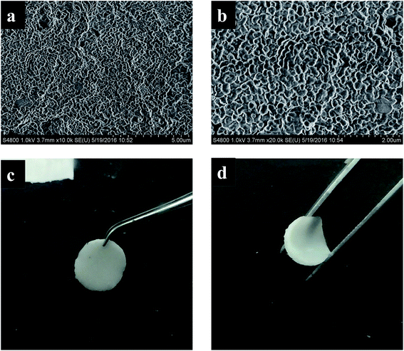
Fig. 1 shows photograph and the scanning electron microscopy (SEM) images of the prepared GPE. From the photograph it can be seen, the gel polymer electrolyte is a white membrane and is flexible which will be useful for designing wearable or other kinds of electrical devices. The SEM images show the GPE membrane formed a uniform structure which is favorable for lithium ion transference. The IR spectra and XRD of the gel polymer electrolyte was also tested and shown in Fig. S1.†The weight content of the liquid electrolyte of the prepared GPE is 71.4%. For comparison, gel polymer electrolyte of different liquid content is synthesized (see ESI†) and the influence on ionic conductivity is shown in Table 1. From the data of Table 1, it is clear that the ionic conductivity increases with the weight content of the liquid electrolyte. But the heat flow of the GPE calculated from DSC test shows a contrary tendency. For comparison, the that the amount of exothermic heat of pure liquid electrolyte heat is also tested by calculating from the heat flow of the DSC test, the value is 405 J g−1. Taking into account of all the factors, the composition of GPE-0 was chosen to be studied in this paper.
| Number | η/% | σ/mS cm−1 | Exothermic heat/J g−1 |
|---|---|---|---|
| 0 | 71.4 | 3.3 | 498 |
| 1 | 72.7 | 3.6 | 595 |
| 2 | 73.4 | 3.9 | 620 |
| 3 | 57.1 | 1.5 | 632 |
Thermal stability is one of the most important factors for the application of the polymer electrolyte. Good thermal stability can definitely enhance the safety property of the lithium ion battery. The thermal properties of the synthesized GPE were tested and presented in Fig. 2. The synthesized gel polymer electrolyte membrane and the commercialized Celgard separators were both heated in the air under the same temperature for same time. When heated at 150 °C for 30 min in air, the gel polymer electrolyte shows no different change, while the commercialized Celgard separators treated under the same conditions suffer from severe thermal shrinkage (Fig. 2b). Then the treated temperature was raised to 200 °C for another 30 min. The gel polymer electrolyte maintained its original dimension, while the commercialized Celgard separator was almost burnt up (Fig. 2c). The shrinkage of the separator could cause severe internal shortcuts, which could lead to fire breakout or battery explosion. It's easy to tell that gel polymer electrolyte gained improved thermal stability than the commercialized separator, which is beneficial for the improvement of safety properties for lithium ion batteries. The thermogravimetric analysis (TGA) and differential scanning calorimetry (DSC) thermograms were shown in Fig. 4. From the DSC thermogram, it can be seen that the GPE start to decompose at 200 °C. The weight loss of GPE from TGA before 200 °C can be ascribed to the evaporation of the liquid solvent. The GPE shows a better flame retarding ability which is an important factor for the enhancement of the safety property of the lithium ion battery. Most of the commercialized separators are combustible due to the component materials. The combustion test of the commercial separator and the gel polymer electrolyte membrane is performed in this paper by setting both of the membranes on fire. When set on fire, the commercial separator shrank severely and on fire immediately. The separator saturated with the electrolyte was also set on fire, the absorbed liquid electrolyte was on fire immediately and the flame was very big. When the gel polymer electrolyte was set on fire, it was on fire after a relatively longer time and the dimension was unchanged during the process. The composite membrane shows better flame retarding ability (Fig. 3). This property also provides a higher safety performance for the composite membrane compared to the commercial separators.
 | ||
| Fig. 2 Photo image of GPE and commercial separator (a) initial state, (b) heat treatment at 150 °C for 30 min and (c) further heat treatment at 200 °C for 30 min. | ||
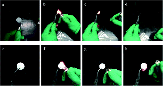 | ||
| Fig. 3 The combustion test of the (a–d) commercialized separator and (e–h) gel polymer electrolyte membrane. | ||
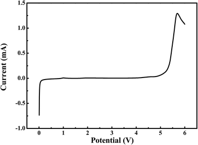
The electrochemical window of the as-obtained gel polymer electrolyte were examined by linear-sweep voltammetry (LSV) with stainless steel as the working electrode and lithium metal as the reference and counter electrode (Fig. 5). The measurements were carried out in the potential range between 0 and 6.0 V (vs. Li/Li+) at a scan rate of 0.5 mV s−1 at room temperature. As presented in Fig. 4, no obvious significant oxidation current was observed until 4.9 V, indicating that the obtained gel-polymer electrolyte samples were electrochemically stable up to 4.9 V (vs. Li/Li+), which is similar to that of the commercialized Celegard membrane soaked with liquid electrolyte because liquid electrolytes are the main composition of the gel polymer electrolyte. This wide electrochemical window is enough for lithium ion batterie.
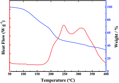 | ||
| Fig. 4 Thermogravimetric analysis and Differential Scanning Calorimetry (DSC) curves of the gel polymer electrolyte. | ||
The ionic conductivities of the composite gel-polymer electrolytes were examined by electrochemical impedance spectroscopy (EIS) with stainless-steel as blocking electrodes. The EIS plot of the prepared GPE is shown in Fig. 5. There is a semicircle at high frequency area and a straight line at low frequency area, which corresponds to the EIS plots in other published literature. The ionic conductivity (σ) of gel electrolyte was calculated using equation of σ = l/(R × A). The ionic conductivity of the gel polymer electrolyte at ambient temperature is 3.3 × 10⁻³ S cm−1, which is comparable to the commercial liquid electrolyte with commercial separator of Celgard saturated with liquid electrolyte (Fig. S2†). This can be ascribed to the high uptake amount of the liquid electrolyte. These data clearly present that the ionic conductivity of the GPE is at the same level for the commercial separator, which is also satisfactory for practical lithium ion batteries. The ionic conductivity of the GPE at different temperature was tested. Fig. 6a shows the EIS plot of the Li/GPE/Li cell at temperatures from 30 to 60 °C, from which the ionic conductivity of the GPE at different temperatures was obtained. The relationship of the lithium ion conductivity and temperature was shown in Fig. 6b. It can be seen that the ionic conductivity of the gel polymer electrolyte remains unchanged with the increasement of temperature and the activation energy is very low. As is known, it's better to have a uniform conductivity over a wide temperature range in order to make electrical devices applicable to a wide range of service temperatures. Hence the synthesized gel polymer electrolyte in this paper has a high conductivity and shows a promising application in electrical devices.
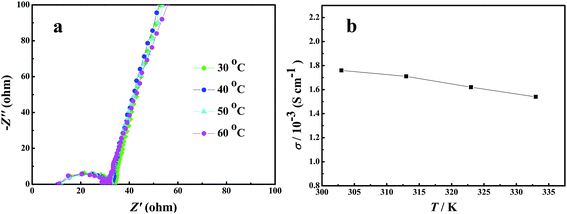 | ||
| Fig. 6 (a) EIS plots of SS/GPE/SS at different temperatures and (b) ionic conductivity of the GPE at different temperatures. | ||
During charge–discharge cycling process of Li-ion batteries, anions such as PF6− in the electrolyte are also movable besides the transfer of lithium ion. Those anions will probably concentrate and be absorbed or decomposed on the surface of electrodes during the cycles, thus will affect the performance of the battery. Therefore, high lithium ion transference number will promote the performance of lithium ion batteries. Here, the lithium-ion transference number of the gel polymer electrolyte is estimated by chronoamperometry by using lithium as both work electrode and counter electrode. The selected impedance spectra and the time dependence response of DC polarization for the gel polymer electrolyte is shown in Fig. 7. The calculated Li+ ion transference numbers by comparing the initial and final current value is 0.76 for the gel polymer electrolyte. That is a satisfactory value when compared to that reported in the literature and is suitable for future application of the GPE. The high lithium transference number of the gel membrane is probably attributed to the large amount of organic solvent trapped within the polymer matrix.
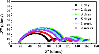
Chemical stability of the gel polymer electrolyte against metal Li is evaluated by monitoring the impedance of a Li/Li symmetric cell during storage at room temperature. The gel polymer electrolyte was cut into pieces and sandwiched between two lithium foils. The impedance of the symmetric cell was monitored to character the chemical stability of the GPE. Some of the selected EIS spectra are displayed in Fig. 8. Initially, the impedance of the cell gradually increased with the storage time, reaching a maximum impedance value of 156 Ω, then decreased a little, finally stabilizes at around 135 Ω. This may be attributed to the formation of a solid electrolyte interphase (SEI) on the lithium surface. Upon time the SEI experiences a series of dissolution and re-formation steps, accounting for the stabilization of the impedance value. This can also been explained in other literature.34 The impedance value change is slightly during this process, which means the GPE shows an excellent chemical stability.
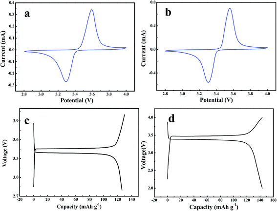
The electrochemical performance of the obtained gel-polymer electrolytes was evaluated in a solid-state battery using the synthesized GPE as both electrolyte and separator with CR2016 coin cell. LiFePO4 as the cathode and Li metal as the counter and reference electrode. The cells were cycled over a voltage range of 2.8–4.0 V. The cyclic voltammetry curve of the battery is presented in Fig. 9a. The oxidation peak is at 3.5 V; the reduction peak is at 3.3 V (vs. Li+/Li). The charge–discharge curve of the battery is shown in Fig. 9c. The charge–discharge profile shows a typical flat-shaped plateau at around 3.4–3.5 V, and the voltage difference between charge and discharge curves is less than 0.2 V, which are corresponds to the cyclic voltammetry test and consistent with LiFePO4 cathode tested in liquid electrolyte (Fig. 9b). The reversible capacity of the LiFePO4 at 0.5C for GPE is 133 mA h g−1 for (Fig. 9c).
The cycling behavior of LiFePO4 tested with gel polymer electrolyte was presented in Fig. 10. The battery was tested by charged and discharged between 2.8–4.0 V under a constant current density of 0.5C (1C = 160 mA g−1). During cycling process, there is no evident capacity fading. The discharge capacity of the cell using GPE is found to be 103 mA h g−1 after 500 cycles. The capacity retention is around 81%, indicating that the gel polymer electrolyte membrane exhibits as a good cycling performance as to the commercial separator (Fig. S4†).
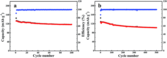 | ||
| Fig. 10 Cycling performance of LiFePO4/GPE/Li battery testing at current density of (a) 0.5C, (b) 0.2C. | ||
Fig. 11 shows the rate performances of LiFePO4 tested with the gel polymer electrolyte membrane. The battery was tested at various charge/discharge current densities from 0.1 to 1C with five cycles performed at each current density. When the cells were charged and discharged at 0.1C, 0.2C, 0.5C and 1C, the discharge capacities of the LiFePO4 were 150, 139, 123 and 109 mA h g−1 (Fig. 11). When the discharge current density went back to 0.5C at the end, the discharge capacity was almost recovered to the original value at the same rate for 130 mA h g−1. The discharge capacity of LiFePO4 tested with gel polymer electrolyte is similar with that tested with traditional liquid electrolyte under the same condition (Fig. S4†). The satisfactory rate capability of the gel polymer electrolyte is probably due to the higher ionic conductivity of the electrolyte.
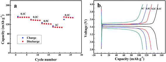 | ||
| Fig. 11 (a) Charge–discharge curves of Li/GPE/LiFePO4 at varying currents from 16 mA g−1 (0.1C) to 160 mA g−1 (1C). (b) Discharge capacities of Li/SPE/AQ at different currents. | ||
4. Conclusion
In summary, a gel polymer electrolyte membrane consisting of PEO as the polymer matrix has been prepared and the performance of the GPE was characterized. The ionic conductivity of the gel polymer electrolyte is 3.3 × 10⁻³ S cm−1 at room temperature, which is the same level of the commercial separator saturating with liquid electrolyte. The lithium ion transference number of the gel polymer membrane is as high as 0.76, which is probably due to the high amount of the absorbed liquid electrolyte. The thermal stability of the GPE is improved a lot which will definitely improve the safety of lithium ion batteries. Meanwhile, the electrochemical performance of the gel membrane was evaluated by fabricating a battery using LiFePO4 as the cathode material and GPE as the electrolyte and separator. The battery shows an initial discharge capacity of 150 mA h g−1 at current density of 16 mA g−1 and 81% of capacity remained after 500 cycles of the charge–discharge process under 0.5C. And the rate capability is also very good when compared with that using commercial separator saturated with liquid electrolyte under the same condition. The GPE prepared here shows promising application ability in lithium ion batteries.Acknowledgements
This work was partially supported by the National Natural Science Foundation of China (No. 21333002), the National Key Research and Development Plan (2016YFB0901503).References
- J. B. Goodenough and J. M. Tarascon, nature, 2008, 451, 652–657 CrossRef PubMed.
- N.-S. Choi, Z. Chen, S. A. Freunberger, X. Ji, Y.-K. Sun, K. Amine, G. Yushin, L. F. Nazar, J. Cho and P. G. Bruce, Angew. Chem., Int. Ed., 2012, 51, 9994–10024 CrossRef CAS PubMed.
- B. Scrosati, J. Hassoun and Y.-K. Sun, Energy Environ. Sci., 2011, 4, 3287 CAS.
- J. B. Goodenough and Y. Kim, J. Power Sources, 2011, 196, 6688–6694 CrossRef CAS.
- G. G. Eshetu, J.-P. Bertrand, A. Lecocq, S. Grugeon, S. Laruelle, M. Armand and G. Marlair, J. Power Sources, 2014, 269, 804–811 CrossRef CAS.
- A. S. Aricò, P. G. Bruce, B. Scrosati, J. M. Tarascon and W. v. Schalkwijk, Nat. Mater., 2005, 4, 366–377 CrossRef PubMed.
- M. Nakayama, S. Wada, S. Kuroki and M. Nogami, Energy Environ. Sci., 2010, 3, 1995–2002 CAS.
- J. Hassoun, P. Reale and B. Scrosati, J. Mater. Chem., 2007, 17, 3668 RSC.
- W. Li, L. Chen, Y. Sun, C. Wang, Y. Wang and Y. Xia, Solid State Ionics, 2017, 300, 114–119 CrossRef CAS.
- J. Yi, X. Liu, S. Guo, K. Zhu, H. Xue and H. Zhou, ACS Appl. Mater. Interfaces, 2015, 7, 23798–23804 CAS.
- K. Fu, Y. Gong, J. Dai, A. Gong, X. Han, Y. Yao, C. Wang, Y. Wang, Y. Chen, C. Yan, Y. Li, E. D. Wachsman and L. Hu, Proc. Natl. Acad. Sci. U. S. A., 2016, 113, 7094–7099 CrossRef CAS PubMed.
- S. Wu, J. Yi, K. Zhu, S. Bai, Y. Liu, Y. Qiao, M. Ishida and H. Zhou, Adv. Energy Mater., 2017, 7, 1601759 CrossRef.
- J. Yi and H. Zhou, ChemSusChem, 2016, 9, 2391–2396 CrossRef CAS PubMed.
- J. Yi, S. Wu, S. Bai, Y. Liu, N. Li and H. Zhou, J. Mater. Chem. A, 2016, 4, 2403–2407 CAS.
- S. S. Zhang and D. T. Tran, J. Mater. Chem. A, 2014, 2, 7383 CAS.
- H. Zhong, C. Wang, Z. Xu, F. Ding and X. Liu, Sci. Rep., 2016, 6, 25484 CrossRef CAS PubMed.
- K. N. Jung, J. I. Lee, J. H. Jung, K. H. Shin and J. W. Lee, Chem. Commun., 2014, 50, 5458–5461 RSC.
- L. Hu and Y. Cui, Energy Environ. Sci., 2012, 5, 6423 Search PubMed.
- M. Que, Y. Tong, G. Wei, K. Yuan, J. Wei, Y. Jiang, H. Zhu and Y. Chen, J. Mater. Chem. A, 2016, 4, 14132–14140 CAS.
- C. Ma, J. Zhang, M. Xu, Q. Xia, J. Liu, S. Zhao, L. Chen, A. Pan, D. G. Ivey and W. Wei, J. Power Sources, 2016, 317, 103–111 CrossRef CAS.
- Y. Zhang, W. Cai, R. Rohan, M. Pan, Y. Liu, X. Liu, C. Li, Y. Sun and H. Cheng, J. Power Sources, 2016, 306, 152–161 CrossRef CAS.
- Y. Zhao, C. Wu, G. Peng, X. Chen, X. Yao, Y. Bai, F. Wu, S. Chen and X. Xu, J. Power Sources, 2016, 301, 47–53 CrossRef CAS.
- D. Zhou, Y.-B. He, R. Liu, M. Liu, H. Du, B. Li, Q. Cai, Q.-H. Yang and F. Kang, Adv. Energy Mater., 2015, 5, 1500353 CrossRef.
- J. Zhang, L. Yue, P. Hu, Z. Liu, B. Qin, B. Zhang, Q. Wang, G. Ding, C. Zhang, X. Zhou, J. Yao, G. Cui and L. Chen, Sci. Rep., 2014, 4, 6272–6279 CrossRef CAS PubMed.
- A. Ngamaroonchote and C. Chotsuwan, J. Appl. Electrochem., 2016, 46, 575–582 CrossRef CAS.
- X. Luo, Y. Liao, H. Xie, Y. Zhou, Q. Huang and W. Li, Electrochim. Acta, 2016, 220, 47–56 CrossRef CAS.
- A. Manuel Stephan, Eur. Polym. J., 2006, 42, 21–42 CrossRef CAS.
- Y. Zhu, S. Xiao, Y. Shi, Y. Yang, Y. Hou and Y. Wu, Adv. Energy Mater., 2014, 4, 1300647 CrossRef.
- Y. Zhu, F. Wang, L. Liu, S. Xiao, Z. Chang and Y. Wu, Energy Environ. Sci., 2013, 6, 618–624 CAS.
- Y. Tominaga and M. Endo, Electrochim. Acta, 2013, 113, 361–365 CrossRef CAS.
- C. V. Amanchukwu, H. H. Chang, M. Gauthier, S. Feng, T. P. Batcho and P. T. Hammond, Chem. Mater., 2016, 28, 7167–7177 CrossRef CAS.
- W. Yang, W. Yang, J. Feng, Z. Ma and G. Shao, Electrochim. Acta, 2016, 210, 71–78 CrossRef CAS.
- Y. Zhu, F. Wang, L. Liu, S. Xiao, Y. Yang and Y. Wu, Sci. Rep., 2013, 3, 3187 CrossRef PubMed.
- C. Fasciani, S. Panero, J. Hassoun and B. Scrosati, J. Power Sources, 2015, 294, 180–186 CrossRef CAS.
- P. Hu, J. Zhao, T. Wang, C. Shang, J. Zhang, B. Qin, Z. Liu, J. Xiong and G. Cui, Electrochem. Commun., 2015, 61, 32–35 CrossRef CAS.
- H. Gao, B. Guo, J. Song, K. Park and J. B. Goodenough, Adv. Energy Mater., 2015, 5, 1402235 CrossRef.
- Y. S. Zhu, S. Y. Xiao, M. X. Li, Z. Chang, F. X. Wang, J. Gao and Y. P. Wu, J. Power Sources, 2015, 288, 368–375 CrossRef CAS.
- H. Cheng, C. Zhu, B. Huang, M. Lu and Y. Yang, Electrochim. Acta, 2007, 52, 5789–5794 CrossRef CAS.
- Y. Tominaga, S. Asai, M. Sumita, S. Panero and B. Scrosati, J. Power Sources, 2005, 146, 402–406 CrossRef CAS.
- S. S. Jeong, Y. T. Lim, Y. J. Choi, G. B. Cho, K. W. Kim, H. J. Ahn and K. K. Cho, J. Power Sources, 2007, 174, 745–750 CrossRef CAS.
Footnote |
| † Electronic supplementary information (ESI) available. See DOI: 10.1039/c7ra02603j |
| This journal is © The Royal Society of Chemistry 2017 |

