 Open Access Article
Hierarchical design of nitrogen-doped porous carbon nanorods for use in high efficiency capacitive energy storage†
Mei Nia,
Zhenghong Huangc,
Xiaoling Zhang*a,
Jinping Liua,
Liang Qiaoa and
Wen Yang *ab
*ab
aKey Laboratory of Cluster Science of Ministry of Education, Beijing Key Laboratory of Photoelectronic/Electrophotonic Conversion Materials, School of Chemistry and Chemical Engineering, Beijing Institute of Technology, 5 Zhongguancun Road, Beijing 100081, P. R. China. E-mail: wenyang@bit.edu.cn; Fax: +86-10-68914780
bState Key Laboratory for Modification of Chemical Fibers and Polymer Materials, School of Material Science and Engineering, DongHua University, 2999 North Renmin Road, Shanghai 201620, China
cLaboratory of Advanced Materials, Department of Materials Science and Engineering, Tsinghua University, Beijing 100084, China
First published on 24th April 2017
Abstract
We report a novel synthesis route for creating 3D interconnected hierarchical porous nitrogen-doped carbon nanorods (3D-IPCRs) using 1D polyaniline nanorods as a precursor and SiO2 as a porogen. The 1D carbon nanorod/SiO2 composites initially formed during carbonization further act as raw materials for a KOH activation process. After subsequent removal of the templates, as-prepared 3D-IPCRs exhibit a high specific surface area (1765 m2 g−1), a large total pore volume (1.06 cm3 g−1), an interconnected porous structure, and a moderate nitrogen doping (2.63 wt%). This interconnectivity is beneficial to improving ion diffusion properties and electrolyte wettability. The resulting carbon exhibits a much lower impedance resistance and smaller contact angle, compared with conventional mesoporous carbon, and thus has better electric double layer performance. As obtained 3D-IPCR electrodes achieve a high specific capacitance of 302 F g−1 at a current density of 0.05 A g−1 in 6 M KOH (two-electrode system), high coulombic efficiency (99.8%) and excellent cycling stability (92.8% of capacitance retention after 10![[thin space (1/6-em)]](https://www.rsc.org/images/entities/char_2009.gif) 000 cycles) even with a high mass loading (11 mg cm−2) and thick electrode film (300 μm). Furthermore, the energy density of 3D-IPCRs reaches 23 W h kg−1, and the power density can be as high as 18.2 kW kg−1 when the energy density remains at 9.11 W h kg−1 in an organic electrolyte.
000 cycles) even with a high mass loading (11 mg cm−2) and thick electrode film (300 μm). Furthermore, the energy density of 3D-IPCRs reaches 23 W h kg−1, and the power density can be as high as 18.2 kW kg−1 when the energy density remains at 9.11 W h kg−1 in an organic electrolyte.
Introduction
Supercapacitors (SCs) based on electrical double-layer charge storage have attracted extensive attention due to their high power density, fast charge–discharge rate and long life cycle.1,2 However, compared to lithium ion batteries, the SCs that are commercially available still cannot satisfy the requirements for large energy density. Although gravimetric capacitance as the figure-of-merit is useful for comparing fully packaged SCs, unrealistic performance may be predicted for packaged devices fabricated from small amounts of electrode materials.3–5 Experimental data have shown that there is a drop in capacitance when the mass loading is increased.4,6 In addition, the increased weight of the electrode on the current collector will obviously determine the thickness of the electrode.7,8 It has been observed that gravimetric capacitance shrinks and the equivalent series resistance (ESR) increases on thicker electrodes because of the reduced adhesion of carbon materials in the thicker electrodes.9 In addition, electrolyte decomposition may be accelerated by loading of carbon materials on a thicker electrode, which will further deteriorate the SCs performance.10,11 Nevertheless, for the purpose of realistic applications, high mass loading (e.g. 10 mg cm−2) of active materials with thick electrode microstructures (100 to 200 μm) are recommended by Simon and Gogotsi.5 Therefore, it is still a great challenge to achieve good capacitance behavior at significantly high electrode material loading.One of the strategies for increasing energy density of SCs is the use of electrode materials with high specific surface area. For that reason, activated carbon is the most used electrode material for SCs.12 Unfortunately, these advantages are severely limited by the decreased electrolyte accessibility associated with the activated carbon electrode materials used currently because most of their surface area resides in micropores.2,13 Mesoporous carbon, fabricated by templates, has also been developed as an electrode material for application in SCs due to controllable pore sizes, which are readily approachable to electrolyte ions.14–18 However, both the gravimetric capacitance and rate performance of nanostructured mesoporous carbon materials are restricted due to its limited surface area, disordered mesostructure and randomly connected porous structures.16,17,19,20 As Oh et al. mentioned in their study, the blind or isolated pores in the carbon framework may not be accessed by electrolytes, and random pore connection makes ion movement difficult.16
Recently, porous carbon materials with interconnected hierachical porous structures, including micropore, mesopore, and macropore, have enhanced electrochemical performance in SCs because of the improvement of ion transport through macropores and mesopores and the improvement of ion storage on the micropore scale.13,15,21 It is believed that an interconnected porous structure not only promotes penetration of electrolyte, but also significantly shortens electron transport distance and increases the surface area of ion accessibility.22 Moreover, the morphology of carbon materials also has great influence on the performance of SCs. 1D porous carbon materials have shown enhanced capacitance, excellent rate performance, and improved stability due to their high conductivity, high surface area, and good chemical stability.23,24 Another strategy for enhancing the performance of SCs is incorporation of heteroatoms in the carbon skeleton as a result of pseudocapacitance.25 Therefore, development of 1D heteroatom-doped carbon materials with interconnected hierachical porous structures are highly desired for enhance both energy density and power density of SCs.
Herein, novel 3D interconnected hierarchical porous nitrogen-doped carbon nanorods (3D-IPCRs) are prepared by direct KOH activation of 1D nitrogen-doped carbon nanorod/SiO2 composites, followed by NH4HF2 removal of the silica hard template. To our best knowledge, only a few reports have mentioned the synthesis of 3D-IPCRs and their application in SCs.23,24 In contrast with traditional KOH activation of mesoporous carbon, the presence of SiO2 during the KOH activation can protect and maintain the original 1D nanostructure of nitrogen-doped carbon nanorods with shortened electron and ion transport distances, and avoid nanostructure fragmentation during KOH activation. Moreover, the novel synthetic strategy provides an opportunity to introduce micropore into the mesopore walls to interconnect blind or isolated pores. After subsequent removal of templates, as-prepared porous carbon has high surface area (1765 m2 g−1), moderate N (2.63 wt%) and O (9.52 wt%) contents, enlarged micropore volume, increased mesopore size, additional macropores, and interconnected hierarchical porous structure. As obtained 3D-IPCRs electrodes with high mass loading (11 mg cm−2) and thick electrode film (300 μm) still deliver a high specific capacity of 302 F g−1 at 0.05 A g−1 and excellent cycle stability in 6 M KOH solutions. Furthermore, the energy density of carbon nanorods reaches 23 W h kg−1, and the power density can be as high as 18.2 kW kg−1 when the energy density remains 9.11 W h kg−1 in an organic electrolyte.
Experimental
Preparation of MeMiCP-800
Typically, 2.0 g aniline was dissolved in 2 M HCl solution, followed by adding 10 g silica colloid solution (∼12 nm, Ludox HS40). The suspension was kept below 10 °C while 4.56 g oxidant (ammonium peroxydisulphate, APS) was added with stirring. The above suspensions was transferred to an autoclave, sealed and heated at 180 °C. After drying in an evaporator, the mixture was pyrolysed at 800 °C in N2 atmosphere, and then cooled to room temperature. For the activation, a mixture of KOH and the prepared carbon (KOH![[thin space (1/6-em)]](https://www.rsc.org/images/entities/char_2009.gif) :
:![[thin space (1/6-em)]](https://www.rsc.org/images/entities/char_2009.gif) carbon = 2
carbon = 2![[thin space (1/6-em)]](https://www.rsc.org/images/entities/char_2009.gif) :
:![[thin space (1/6-em)]](https://www.rsc.org/images/entities/char_2009.gif) 1, weight ratio) was heated to 800 °C and kept for 1 h in N2 flow. The activated mixture was subsequently washed with HCl and deionized water until the supernatant became neutral. The silica templates were etched away by NH4HF2 to obtain the 3D-IPCRs labelled as MeMiCP-800.
1, weight ratio) was heated to 800 °C and kept for 1 h in N2 flow. The activated mixture was subsequently washed with HCl and deionized water until the supernatant became neutral. The silica templates were etched away by NH4HF2 to obtain the 3D-IPCRs labelled as MeMiCP-800.
Characterization
Morphology was observed using transmission electron microscopy (TEM, FEI Tecnai G2 F20) and scanning electron microscopy (SEM, Hitachi S4800). X-ray diffraction (XRD) with CuKα radiation was measured using a diffractometer (Rigaku). The thermogravimetric analysis (TGA) was performed in a DTG-60 (TGA, SHIMADZU). X-ray photoelectron spectroscopy (XPS) were recorded on a Thermo Scientific ESCALab 250Xi system. The Raman spectrum was acquired on a Renishaw-2000 spectrometer. Nitrogen adsorption–desorption isotherms were measured at 77 K with an Autosorb-iQ2 (Quantachrome) analyzer after degassing the sample at 300 °C for 6 h.Preparation of electrodes and electrochemical measurement
In a three-electrode device, the supercapacitor tests of the carbon materials were measured using Hg/HgO reference electrode and platinum foil counter electrode. The samples were mixed with acetylene black and poly(tetrafluoroethylene) (PTFE) binder in a weight ratio of 8![[thin space (1/6-em)]](https://www.rsc.org/images/entities/char_2009.gif) :
:![[thin space (1/6-em)]](https://www.rsc.org/images/entities/char_2009.gif) 1
1![[thin space (1/6-em)]](https://www.rsc.org/images/entities/char_2009.gif) :
:![[thin space (1/6-em)]](https://www.rsc.org/images/entities/char_2009.gif) 1; then the slurry was loaded into Ni foam, and dried at 80 °C. The area of the electrodes were about 1 cm2 (mass loading of active electrode: 3–5 mg cm−2). The electrochemical behavior of electrodes was measured in 6 M KOH electrolyte. In a two-electrode cell, the samples were mixed with acetylene black and PTFE binder in a weight ratio of 8
1; then the slurry was loaded into Ni foam, and dried at 80 °C. The area of the electrodes were about 1 cm2 (mass loading of active electrode: 3–5 mg cm−2). The electrochemical behavior of electrodes was measured in 6 M KOH electrolyte. In a two-electrode cell, the samples were mixed with acetylene black and PTFE binder in a weight ratio of 8![[thin space (1/6-em)]](https://www.rsc.org/images/entities/char_2009.gif) :
:![[thin space (1/6-em)]](https://www.rsc.org/images/entities/char_2009.gif) 1
1![[thin space (1/6-em)]](https://www.rsc.org/images/entities/char_2009.gif) :
:![[thin space (1/6-em)]](https://www.rsc.org/images/entities/char_2009.gif) 1 and formed into pellets (300 μm in thickness). Then the pellets were pressed on Ni foam, and dried at 80 °C. The two-electrode system was assembled with two nearly identical electrodes using membrane as separator, with 6 M KOH aqueous solution as electrolyte. The mass loading of active electrode materials of MeMiCP-800 was about 11 mg cm−2. Two-electrode system tests with 1 M LiPF6 in EC/DMC used as electrolyte were conducted in a 2032-type cell. The mass loading of active electrode materials of MeMiCP-800 was about 1 mg cm−2. The galvanostatic charge/discharge studies were measured on an Arbin testing system. Electrochemical Impedance Spectroscopy (EIS) was collected over the frequency range from 100 kHz to 0.01 Hz. The measured specific capacitance of acetylene black was about 7 F g−1 in 6 M KOH electrolyte in a three-electrode cell. In a three-electrode cell, the specific capacitance was calculated from:
1 and formed into pellets (300 μm in thickness). Then the pellets were pressed on Ni foam, and dried at 80 °C. The two-electrode system was assembled with two nearly identical electrodes using membrane as separator, with 6 M KOH aqueous solution as electrolyte. The mass loading of active electrode materials of MeMiCP-800 was about 11 mg cm−2. Two-electrode system tests with 1 M LiPF6 in EC/DMC used as electrolyte were conducted in a 2032-type cell. The mass loading of active electrode materials of MeMiCP-800 was about 1 mg cm−2. The galvanostatic charge/discharge studies were measured on an Arbin testing system. Electrochemical Impedance Spectroscopy (EIS) was collected over the frequency range from 100 kHz to 0.01 Hz. The measured specific capacitance of acetylene black was about 7 F g−1 in 6 M KOH electrolyte in a three-electrode cell. In a three-electrode cell, the specific capacitance was calculated from:| C = It/mΔV | (1) |
| C = 2It/mΔV | (2) |
| E = 1/2C(ΔV)2 | (3) |
| P = E/t | (4) |
Results and discussion
Structural characterization of samples
KOH activation has been used as an effective strategy to make 1D carbon materials attaining a high-surface area and porous structure. During the pyrolysis of the mixture of carbon nanorods and KOH, the process starts with solid–solid reactions and then proceeds by solid–liquid reactions, including the oxidation of carbon to carbonate and carbon oxide, the reduction of potassium (K) compounds to form metallic K, and other reactions among various active intermediates, leading to a surface area of even higher than 3000 m2 g−1.11,26 However, it is still a challenge to use the KOH activation process to develop 1D carbon materials with porosity, especially with an interconnected hierarchical porous structure, because the original 1D nanostructures are destroyed under harsh conditions.27To address this problem, in the present study SiO2 hard templates were used as structural support for 1D carbon materials to prevent collapse of the 1D nanostructure caused by the KOH activation. In contrast with traditional KOH activation of mesoporous carbon, the presence of SiO2 during the KOH activation could protect and maintain the original 1D nanostructures of the carbon, while suppressing nanostructures fragmentation. After subsequent etching of the silica hard templates, randomly distributed mesopores in the skeleton of carbon nanorods were enlarged and interconnected by extra micropores introduced by KOH activation.
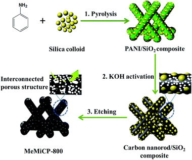
The synthesis process of 3D-IHPCRs is illustrated in Scheme 1. First, aniline polymers co-assembled with colloidal silica nanoparticles are pyrolyzed at 800 °C to obtain 1D nitrogen-doped carbon nanorod/SiO2 composites, providing morphology control and pore size adjustability. Moreover, nitrogen-containing precursors can incorporate N atoms into the carbon skeleton during pyrolysis. Second, the initially formed 1D carbon nanorod/SiO2 composites are directly used as raw materials for the KOH activation process at 800 °C without removing hard templates. It should be noted that the 1D nanostructures of the original carbon nanorods are maintained during the KOH activation process probably due to the SiO2, which can help prevent the collapse of 1D nanostructures of the carbon materials in harsh reaction conditions. Third, after removing silica hard templates, micropores are introduced into the skeleton of mesoporous carbon nanorods and the mesopores are enlarged and interconnected, resulting in the desired 3D-IHPCRs labeled as MeMiCP-800. To further confirm the superior electrochemical performance of MeMICP-800, as-prepared MeMiCP-800 is compared with carbon nanorods derived from polyaniline (CP), mesoporous carbon nanorods derived from polyaniline nanorod/SiO2 composites (MeCP), and microporous carbon nanorods obtained by chemical activation of carbon nanorods (MiCP-800), as well as hierarchical porous carbon prepared by chemical activation of the carbon nanorod/SiO2 precursor at 700 °C (MeMiCP-700). One commercial carbon black, BP2000, is used for comparison of electrochemical performance.
Fig. 1 and S1† show SEM images of MeCP, MeMiCP-800, CP, MiCP-800, and MeMiCP-700. As shown in Fig. 1a, MeCP prepared from PANI/SiO2 nanorods have an average diameter of 200 nm. The mesoporous structure of MeCP is confirmed by TEM showing that mesopores are well-developed (Fig. 1b, S2a†). As seen in the SEM image (Fig. 1d), MeMiCP-800 retain the original 1D nanorod shape of the PANI/SiO2. The TEM images of MeMiCP-800 highlight its 3D interconnected hierarchical porous structure and the average diameter of the nanorods decreased to 150 nm without obvious structural collapse (Fig. 1e and 2a and b). The retention of the 1D nanorods is attributed to the sequence of experimental steps (KOH activation first and then removal of the template), indicating that SiO2 hard templates play an important role in maintaining the morphology. Moreover, Fig. 2a and b show that the neighboring mesopores are connected to each other after KOH activation and removal of the added colloidal silica. The 1D carbon nanorods with plentiful interconnected hierarchical pores (micro-, meso- and macropores) are urgently needed because they allow rapid ion diffusion.22
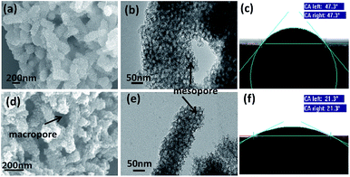 | ||
| Fig. 1 SEM images: (a) MeCP; (d) MeMiCP-800. TEM images: (b) MeCP; (e) MeMiCP-800. Wetting contact angles (CA) of a water droplet on (c) MeCP and (f) MeMiCP-800 substrates. | ||
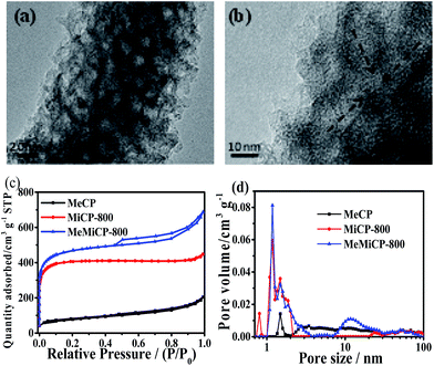 | ||
| Fig. 2 (a) and (b) HRTEM image of MeMiCP-800. (c) Nitrogen adsorption–desorption isotherms and (d) pore size distributions of samples. | ||
Raman and XRD results for samples are shown in Fig. S3.† All samples exhibit two characteristic peaks corresponding to D-band and G-band. The intensity ratio of ID/IG obviously increases from 0.98 for MeCP to 1.03 for MeMiCP-800, indicating the increased defects after activation with KOH. As shown in Fig. S3b,† the (002) reflection in the XRD patterns can be observed at 25.2° for MeCP, originating from the interlayer stacking of the graphitic layer.28 Compared to the MeCP, the (002) peak of MeMiCP-800 has slightly shifted to lower angles (24.6°) and is broadened, indicating a larger interlayer distance, and an increased disordered structure after activation which is consistent with the Raman spectral analysis.29 Meanwhile, both MeCP and MeMiCP-800 are hydrophilic and can be wetted by a water droplet (Fig. 1c and f). The contact angle of the MeCP surface is 47.3°. MeMiCP-800 could absorb the water droplet within its 3D interconnected hierarchical porous structure, demonstrating improvement of the electrolyte wettability (contact angle, CA = 21.3°).30–32
The N2 adsorption–desorption isotherms were acquired to analyse the porosities of the resulting carbon materials (Fig. 2c). The Brunauer–Emmett–Teller (BET) surface areas and pore structure parameters are shown in Table 1. It can be seen that the isotherm of MiCP-800 can be classified as a type I isotherm, revealing a microporous structure (Fig. 2c). The isotherm of MeCP exhibited type IV isotherm characteristics, and an H3 hysteresis loop can be observed, indicating the presence of mesopores in the sample.33–35 This behavior is similar to that of mesophase pitch and polyacrylonitrile-derived carbon materials using colloidal silica as a hard template, where the mesopores make up most of the total pores.20,36 After KOH activation, the isotherm of MeMiCP-800 shows a combined type I/IV isotherm with strong adsorption at low pressure and an H3 hysteresis loop, indicating that micro- and mesopores coexist in the sample and form an interconnected pore system (Fig. 2c).37–40 Pore size distributions of MeCP and MeMiCP-800 obtained by the Density Functional Theory (DFT) method clearly show the increasing diameter of the mesopore due to KOH activation, and the mesopore volume increases from 0.24 to 0.50 cm3 g−1 (Fig. 2d, Table 1). In MeMiCP-800, the micropores can be readily further activated to form an interconnected pore structure via mesopore widening, wall crumbling and fusing (Fig. 2d).41 This 3D hierarchical nano-architecture of MeMiCP-800 with high specific surface area (1765 m2 g−1) and large pore volume (1.06 cm3 g−1) is highly desirable for energy storage and conversion than activated carbon.42
| Carbon type | SBET (m2 g−1) | Smicroa (m2 g−1) | Vmicrob (cm3 g−1) | Vmesoc (cm3 g−1) |
|---|---|---|---|---|
| a DFT micropore specific surface area (pore size < 2 nm).b DFT micropore volume (pore size < 2 nm).c DFT mesopore volume (2 nm < pore size < 50 nm). | ||||
| MeCP | 272 | 71 | 0.03 | 0.24 |
| MiCP-800 | 1558 | 1285 | 0.50 | 0.10 |
| MeMiCP-800 | 1765 | 1257 | 0.49 | 0.50 |
The XPS survey spectras of the MeMiCP-800 sample are shown in Fig. S4.† Table S1† shows nitrogen and oxygen contents of 2.63 and 9.52 at%, respectively. The peaks around 398.1, 400.0 and 400.9 eV correspond to pyridinic (N-6, 11.7 at%), pyrrolic (N-5, 51.6 at%) and quaternary (N-Q, 34.4 at%) chemical binding states.43 This demonstrates that N atoms within the PANI are partly converted into N-5, N-6 or N-Q by pyrolysis.44 Owing to the incorporation of oxygen during the polymerization process of the PANI precursor and chemical activation, the existence of oxygen functional groups in the PANI-derived carbon is almost unavoidable.23,41 The deconvoluted C 1s XPS can be fit by four characteristic peaks at 284.7, 285.2, 286.2, and 288.2 eV, attributed to C–C, C–N, C–O, and C![[double bond, length as m-dash]](https://www.rsc.org/images/entities/char_e001.gif) O, respectively.41,44,45 The binding energies around 531.6 and 533 eV, represent C
O, respectively.41,44,45 The binding energies around 531.6 and 533 eV, represent C![[double bond, length as m-dash]](https://www.rsc.org/images/entities/char_e001.gif) O quinone type groups, C–OH phenol groups and/or C–O–C ether groups, respectively. Based on the XPS results, it is shown that N and O functional groups are contained in the carbon frame. The TGA curve of the MeMiCP-800 shows complete decomposition at 616 °C (Fig. S5†), indicating that the SiO2 had been removed completely.
O quinone type groups, C–OH phenol groups and/or C–O–C ether groups, respectively. Based on the XPS results, it is shown that N and O functional groups are contained in the carbon frame. The TGA curve of the MeMiCP-800 shows complete decomposition at 616 °C (Fig. S5†), indicating that the SiO2 had been removed completely.
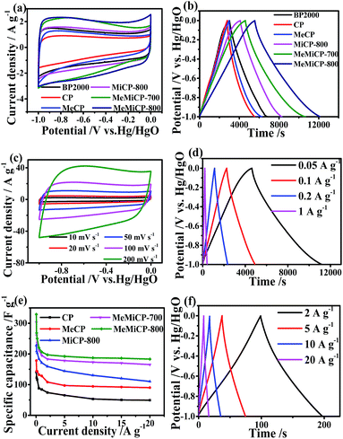
Electrochemical performance of samples
In order to evaluate the capacitive characteristics of the obtained carbon materials for capacitors, cyclic voltammetry (CV), galvanostatic charge/discharge (GCD) and electrochemical impedance were tested via a three-electrode device. Fig. 3a shows the CV curves of samples at the scan rate of 10 mV s−1. Compared with that of commercial carbon black (BP2000), the CV curves of MeMiCP-700 and MeMiCP-800 at about −0.6 V display slight humps, which can be attributed to the pseudocapacitance from redox reaction of N/O functional groups, i.e. quinone group and N-6.23,46,47 Note that as-prepared MeMiCP-800 has relatively low electrochemical active N-6 contents. Thus, it may be deduced that the pseudocapacitance mainly comes from oxygen functional groups attached to the carbon, formed during the KOH activation process. The MeMiCP-800 retains rectangular voltammogram profiles when the scan rate is increased to 200 mV s−1 (Fig. 3c), indicating MeMiCP-800 has high rate capability at high scan rate.41The capacitive performance was further tested with GCD measurements, as shown in Fig. 3b. The specific capacitance values were calculated using eqn (1). GCD curves of the six electrodes appear nearly triangular and symmetrical, indicating good capacitive properties.48 The capacitances of the BP2000, CP, MeCP, MiCP-800, MeMiCP-700, and MeMiCP-800 electrodes calculated from the discharge curves are 194, 141, 178, 228, 303 and 329 F g−1 at 0.05 A g−1, respectively, in good agreement with the CV results. The normalized capacitance of MeMiCP-800 is 18.6 μF cm−2, which is larger than that of commercial activated carbon BP2000 (12.9 μF cm−2), but smaller than that of MeCP (65.4 μF cm−2), indicating that the BET surface area of MeMiCP-800 were increased and micropores were introduced on the mesopore walls to interconnect blind or isolated mesopores, resulting in an enhanced double layer capacitance and electrolyte wettability, while the reduced nitrogen contents lead to the decline of pseudocapacitance, which confirmed by the decreased capacitance per unit area (Fig. S6, Table S1†).47
The rate performance was also evaluated by a three-electrode device. The specific capacitances of MeMiCP-800 in 6 M KOH are 329, 268, 206, 187 and 183 F g−1 at current densities of 0.05, 0.1, 1, 10 and 20 A g−1, respectively (Fig. 3d and f). The specific capacitance of the MeMiCP-800 sample dropped by 44% (from 329 to 183 F g−1) as the current density increased from 0.05 to 20 A g−1, while the MeCP lost 50% of its capacitance (from 178 to 90 F g−1) under the identical conditions (Fig. 3e). Therefore, the interconnected hierarchical porous structures are capable of providing a short and unimpeded diffusion channel for electrolyte ions in the charge–discharge process to achieve higher capacitance and better charge/discharge rate.
As shown in the Nyquist plot (Fig. 4a), MeMiCP-800 displays low equivalent series resistance in the high frequency region, better than that of other samples. The low interface resistance may be attributed to the improved wettability of MeMiCP-800.25 The arc in the EIS diagram of MeMiCP-800 indicates a minimized charge transfer resistance in the MeMiCP-800 electrode.40 In Fig. 4b, the corresponding relaxation time constant τ0 exhibits a similar trend. The MeMiCP-800 samples demonstrated a frequency response of 0.52 Hz, higher than that of MeCP (0.27 Hz), corresponding to relaxation time constants τ0 = 1.92 s and 3.70 s, respectively (τ0 = 1/f0).48,49 The relaxation time constant corresponds to the ion transport time in internal pores, and a smaller time constant shows easier ion diffusion. The better rate performance of the MeMiCP-800 sample is attributed to the KOH activation process which increased the mesopore volume from 0.24 cm3 g−1 to 0.50 cm3 g−1 and led to interconnected pore structures.50,51 The interconnected structure of MeMiCP-800 with the largest mesopore volumes further favors rapid ion transport channels, leading to higher specific capacitance at high current density.
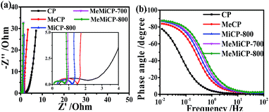 | ||
| Fig. 4 (a) Nyquist plots (b) Bode plots of phase angle versus frequency of all samples measured in a three-electrode system in 6 M KOH. | ||
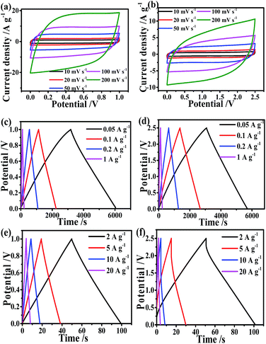
To evaluate the practical applications of MeMiCP-800 for SCs, the electrochemical behavior of MeMiCP-800 was measured in a two-electrode device using 6 M KOH and 1 M LiPF6 EC/DMC as electrolytes. The CV curves of MeMiCP-800 were tested at various scan rates in the voltage window of 0 to 1 V and 0 to 2.5 V (Fig. 5a and b). All the curves display similar rectangular shape without obvious redox peaks, showing typical capacitive behavior.44,52 When the scan rate was increased to 200 mV s−1, the CV curves of MeMiCP-800 retained a rectangular shape with little polarization (Fig. 5a and b), indicating that the MeMiCP-800 has excellent rate performance. Fig. 5c–f show the GCD curves of MeMiCP-800 at various current densities from 0.05 to 20 A g−1. The specific capacitance of MeMiCP-800 reached 302 and 105 F g−1 at 0.05 A g−1 in 6 M KOH and 1 M LiPF6 EC/DMC electrolytes, respectively. In this study, our electrodes were 300 μm in thickness, and the active electrodes had mass loadings of 11 mg cm−2 in aqueous electrolyte, which satisfied the suggested standard by Simon and Gogotsi.5 The curves are nearly linear, and MeMiCP-800 discharged without obvious IR drop even when the current density was increased to 20 A g−1 in KOH electrolyte, indicating small ESR, high coulombic efficiency and excellent reversibility. MeMiCP-800 showed higher capacitive performance, especially compared with previous reports for carbon-based materials (as shown in Table S2†). The excellent electrochemical performance is attributed to the 3D interconnected hierarchical porous texture and the 1D nanostructure of MeMiCP-800, which can promote penetration of electrolyte, shorten electron transport distance and increase the surface area of ion accessibility in the capacitor.
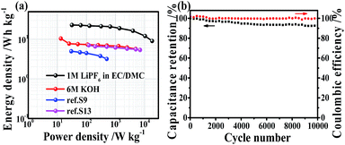
The Ragone plot of the symmetric supercapacitor is shown in Fig. 6a. The energy density of MeMiCP-800 reaches 23 W h kg−1 in the organic electrolyte at a current density of 0.1 A g−1, which is better than that of the commercial devices (<3 W h kg−1).5 The power density of MeMiCP-800 reaches 18.2 kW kg−1 at an energy density of 9.11 W h kg−1 in organic electrolyte. In the 6 M KOH electrolyte, MeMiCP-800 shows performance higher or comparable to that of other reports based on lower mass loading of electrode. The reason is that the S-doped carbon/graphene material reported in ref. S3† has low mesopore volume, and the nitrogen-doped porous carbon nanofibers reported in ref. S13† have low micropore volume. Therefore, the MeMiCP-800, which contains both large micropore and mesopore volumes, results in better performance as a supercapacitor electrode. Moreover, MeMiCP-800 shows high coulombic efficiency and 92.8% capacitance retention after 10![[thin space (1/6-em)]](https://www.rsc.org/images/entities/char_2009.gif) 000 consecutive cycles (Fig. 6b), indicating that the charge/discharge process of the electrode is highly invertible.
000 consecutive cycles (Fig. 6b), indicating that the charge/discharge process of the electrode is highly invertible.
Conclusions
In summary, 3D-IPCRs with high surface area (1765 m2 g−1) and moderate N (2.63 wt%) and O (9.52 wt%) contents were fabricated by using 1D nitrogen-doped carbon nanorod/SiO2 as raw materials for KOH activation. Compared to mesoporous carbon, the carbon materials with unique 3D interconnected hierarchical porous structures display better electron transport, ion diffusion, and electrolyte surface wettability, and thus have a better electric double layer performance, even at high mass loading and greater electrode thickness. Additionally, heteroatoms doping in the carbon framework could also provide pseudocapacitance, and thus can further enhance the electrochemical performance of SCs. In conclusion, our results may provide new insights for synthesis 3D-IPCRs, which are promising candidates for applications in EDLC capacitors or other electrochemical energy storage devices.Acknowledgements
This work was financially supported by the Natural Science Foundation of Beijing Municipality (No. 2172051), National Natural Science Foundation of China (No. 21575015, 21505004), Beijing National Laboratory for Molecular Sciences (BNLMS) (20140121), the Open Funds of the State Key Laboratory of Electroanalytical Chemistry (SKLEAC201708), Research Fund for the Doctoral Program of Higher Education of China (RFDP) (No. 20121101110049) and the 111 Project (B07012). We thank Prof. Gaoping Cao (Research Institute of Chemical Defense) for help with testing, and Prof. Zhiqiang Shi (Tianjin Polytechnic University), Prof. Shaojun Guo (Peking University), and Prof. Ruitao Lv (Tsinghua University) for useful discussions.References
- M. Winter and R. J. Brodd, Chem. Rev., 2004, 104, 4245–4269 CrossRef CAS PubMed.
- W. Lu, Carbon nanotubes, carbon nanotubes supercapacitors, Wiley-VCH, Germany, 2004 Search PubMed.
- A. Burke, Electrochim. Acta, 2007, 53, 1083–1091 CrossRef CAS.
- M. D. Stoller and R. S. Ruoff, Energy Environ. Sci., 2010, 3, 1294–1301 CAS.
- Y. Gogotsi and P. Simon, Science, 2011, 334, 917–918 CrossRef CAS PubMed.
- L. B. Hu, J. W. Choi, Y. Yang, S. Jeong, F. L. Mantia and Y. Cui, et al., Proc. Natl. Acad. Sci. U. S. A., 2009, 106, 21490–21494 CrossRef CAS PubMed.
- S. H. Yoon, J. H. Jang, B. H. Ka and S. M. Oh, Electrochim. Acta, 2005, 50, 2255–2262 CrossRef CAS.
- C. Y. Wan, L. Y. Yuan and H. Y. Shen, Int. J. Electrochem. Sci., 2014, 9, 4024–4038 Search PubMed.
- S. Kumagai, K. Mukaiyachi and D. Tashima, Journal of Energy Storage, 2015, 3, 10–17 CrossRef.
- Y. G. Wang, L. Cheng and Y. Y. Xia, J. Power Sources, 2006, 153, 191–196 CrossRef CAS.
- J. C. Wang and S. Kaskel, J. Mater. Chem., 2012, 22, 23710–23725 RSC.
- L. Wei and S. G. Yu, Nano Energy, 2012, 1, 552–565 CrossRef CAS.
- F. Béguin, V. Presser, A. Balducci and E. Frackowiak, Adv. Mater., 2014, 26, 2219–2251 CrossRef PubMed.
- M. Sevilla, S. Álvarez, T. A. Centeno, A. B. Fuertes and F. Stoeckli, Electrochim. Acta, 2007, 52, 3207–3215 CrossRef CAS.
- Q. Zhang, F. Wei and D. W. Wang, Advanced hierarchical nanostructured materials, Wiley-VCH, 2014, pp. 443–457 Search PubMed.
- S. H. Yoon, J. Lee, T. Hyeon and S. M. Oh, J. Electrochem. Soc., 2000, 147, 2507–2512 CrossRef CAS.
- H. Nishihara and T. Kyotani, Adv. Mater., 2012, 24, 4473–4498 CrossRef CAS PubMed.
- W. Yang, M. Ni, X. Ren, Y. F. Tian, N. Ling and Y. F. Su, et al., Curr. Opin. Colloid Interface Sci., 2015, 20, 416–428 CrossRef CAS.
- A. H. Lu and F. Schüth, C. R. Chim., 2005, 8, 609–620 CrossRef CAS.
- J. Lee, S. J. Han and T. Hyeon, J. Mater. Chem., 2004, 14, 478–486 RSC.
- Z. Y. Yuan and B. L. Su, J. Mater. Chem., 2006, 16, 663–677 RSC.
- Y. Liang, D. C. Wu and R. W. Fu, Langmuir, 2009, 25, 7783–7785 CrossRef CAS PubMed.
- W. Li, F. Zhang, Y. Q. Dou, Z. X. Wu, H. J. Liu, X. F. Qian, D. Gu, Y. Y. Xia, B. Tu and D. Y. Zhao, Adv. Energy Mater., 2011, 1, 382–386 CrossRef CAS.
- D. Y. Lee, J. Y. Jung, M. J. Jung and Y. S. Lee, Chem. Eng. J., 2015, 263, 62–70 CrossRef CAS.
- T. Q. Lin, I. W. Chen, F. X. Liu, C. Y. Yang, H. Bi and F. F. Xu, et al., Science, 2015, 350, 1508–1513 CrossRef CAS PubMed.
- L. Zhang, F. Zhang, X. Yang, G. K. Long, Y. P. Wu and T. F. Zhang, et al., Sci. Rep., 2013, 3, 1408–1417 Search PubMed.
- S. H. Yoon, S. Lim, Y. Song, Y. Ota, W. M. Qiao, A. Tanaka and I. Mochida, Carbon, 2004, 42, 1723–1729 CrossRef CAS.
- Y. Zhu, S. Murali, M. D. Stoller, K. J. Ganesh, W. Cai and P. J. Ferreira, et al., Science, 2011, 332, 1537–1541 CrossRef CAS PubMed.
- H. L. Wang, Z. W. Xu, A. Kohandehghan, Z. Li, K. Cui and X. H. Tan, et al., ACS Nano, 2013, 7, 5131–5141 CrossRef CAS PubMed.
- W. Wang, S. R. Guo, M. Penchev, I. Ruiz, K. N. Bozhilov and D. Yan, et al., Nano Energy, 2013, 2, 294–303 CrossRef CAS.
- M. M. Vadiyar, S. C. Bhise, S. K. Patil, S. S. Kolekar, A. R. Shelke and N. G. Deshpande, et al., Chem. Commun., 2016, 52, 2557–2560 RSC.
- J. Zhao, H. W. Lai, Z. Y. Lyu, Y. F. Jiang, K. Xie and X. Z. Wang, et al., Adv. Mater., 2015, 27, 3541–3545 CrossRef CAS PubMed.
- G. Y. Gor, M. Thommes, K. A. Cychosz and A. V. Neimark, Carbon, 2012, 50, 1583–1590 CrossRef CAS.
- V. M. Gun'ko, Appl. Surf. Sci., 2014, 307, 444–454 CrossRef.
- G. Wang, Y. H. Sun, D. B. Li, H. W. Lian, R. H. Dong and X. L. Feng, et al., Angew. Chem., Int. Ed., 2015, 54, 15191–15196 CrossRef CAS PubMed.
- Z. Li and M. Jaroniec, J. Am. Chem. Soc., 2001, 123, 9208–9209 CrossRef CAS PubMed.
- L. Zhang, X. Yang, F. Zhang, G. K. Long, T. F. Zhang and K. Leng, et al., J. Am. Chem. Soc., 2013, 135, 5921–5929 CrossRef CAS PubMed.
- L. Zhang, F. Zhang, X. Yang, G. K. Long, Y. P. Wu and T. F. Zhang, et al., Sci. Rep., 2013, 3, 1408–1417 Search PubMed.
- J. Pampel and T. P. Fellinger, Adv. Energy Mater., 2016, 6, 1502389–1502397 CrossRef.
- S. J. Gregg and K. S. W. Sing, Adsorption, Surface Area and Porosity, Academic Press, New York, 1982 Search PubMed.
- X. M. Fan, C. Yu, J. Yang, Z. Ling, C. Hu and J. S. Qiu, Adv. Energy Mater., 2015, 5, 401761–401767 Search PubMed.
- A. Ahmadpour and D. D. Do, Carbon, 1996, 34, 471–479 CrossRef CAS.
- M. Sevilla, L. H. Yu, C. O. Ania and M. M. Titirici, ChemElectroChem, 2014, 1, 2138–2145 CrossRef CAS.
- F. B. Su, C. K. Poh, J. S. Chen, G. W. Xu, D. Wang and Q. Li, et al., Energy Environ. Sci., 2011, 4, 717–724 CAS.
- H. Tong, W. L. Bai, S. H. Yue, Z. Z. Gao, L. Lu, L. F. Shen, S. Y. Dong, J. J. Zhu, J. P. He and X. G. Zhang, J. Mater. Chem. A, 2016, 4, 11256–11263 CAS.
- D. W. Wang, F. Li, L. C. Yin, X. Lu, Z. G. Chen, I. R. Gentle and G. Q. Lu, Chem.–Eur. J., 2012, 18, 5345–5351 CrossRef CAS PubMed.
- B. Xu, H. Duan, M. Chu, G. P. Cao and Y. S. Yang, J. Mater. Chem. A, 2013, 1, 4565–4570 CAS.
- C. W. Lee, S. B. Yoon, H. K. Kim, H. C. Youn, J. Han and K. C. Roh, et al., J. Mater. Chem. A, 2015, 11, 2314–2322 Search PubMed.
- L. L. Jiang, L. Z. Sheng, C. L. Long and Z. J. Fan, Nano Energy, 2015, 11, 471–480 CrossRef CAS.
- L. Qie, W. Chen, H. Xu, X. Xiong, Y. Jiang and F. Zou, et al., Energy Environ. Sci., 2013, 6, 2497–2504 Search PubMed.
- Z. J. Zhu, H. Jiang, S. J. Guo, Q. L. Cheng, Y. J. Hu and C. Z. Li, Sci. Rep., 2015, 5, 15936–15941 CrossRef CAS PubMed.
- Q. H. Liang, L. Ye, Z. H. Huang, Q. Xu, Y. Bai and F. Kanga, et al., Nanoscale, 2014, 6, 13831–13837 RSC.
Footnote |
| † Electronic supplementary information (ESI) available: SEM images, TEM images, Raman spectra, XRD patterns, XPS spectrum, thermogravimetric analysis (TGA) curve, surface concentration (in at%) of the nitrogen and oxygen species, performance of various carbon-based ECs in aqueous electrolytes. See DOI: 10.1039/c7ra02425h |
| This journal is © The Royal Society of Chemistry 2017 |

