DOI:
10.1039/C7RA02112G
(Paper)
RSC Adv., 2017,
7, 17244-17253
Highly efficient red emission and multiple energy transfer properties of Dy3+/Mn4+ co-doped Ca14Zn6Ga10O35 phosphors
Received
20th February 2017
, Accepted 12th March 2017
First published on 20th March 2017
Abstract
Novel Dy3+/Mn4+ co-doped Ca14Zn6Ga10O35 phosphors have been synthesized by a solid state reaction technique. Strong blue emission ranging from 370 nm to 500 nm was observed for the Ca14Zn6Ga10O35 host, attributed to the recombination of a donor–acceptor pair through a tunneling process. High internal and external quantum efficiencies of 64.4% and 56.2% respectively were obtained under the excitation of 310 nm in Mn4+ doped Ca14Zn6Ga10O35. This external quantum efficiency is the highest one reported for Mn4+ doped oxides. The temperature-dependent quantum efficiency of Ca14Zn6Ga10O35:Mn4+ is also measured, indicating the unchanged absorption of the excitation light with temperature. In Ca14Zn6Ga10O35:Dy3+, Mn4+ phosphors, multiple energy transfer from the host to Dy3+ and from Dy3+ to Mn4+ is observed and is confirmed to be a result of the dipole–dipole interaction. The emission changes from deep blue to white to deep red according to the different Dy3+/Mn4+ concentration ratio, and the warm white emission can be realized with the chromaticity coordinate (0.345, 0.275), CCT 3525 K and CRI 87. These results suggest that Ca14Zn6Ga10O35:Mn4+ phosphors have potential application as high efficiency red phosphors for solid-state lighting, while Dy3+/Mn4+ co-doped Ca14Zn6Ga10O35 phosphors can be used as a single-phased white phosphor.
1 Introduction
The Mn4+ ion, which is similar to the isoelectronic Cr3+ (d3), gives a rather complicated optical spectrum. It shows absorption in the whole ultraviolet region1,2 and the subsequently emitted phosphorescence is in the deep red (620–720 nm) due to transition from the 2E → 4A2.3,4 Thus, Mn4+-doped red phosphors might have potential application in lighting,5 holography,6 lasers,7 and dosimetry.8
As a kind of red phosphor with a high quantum efficiency, Mn4+ activated fluoride phosphors have attracted considerable interest.9 Mn4+ doped K2TiF6 red phosphors show internal quantum yields as high as 98%, and high performance white LEDs with 3556 K correlated color temperature, 81 color rendering index (Ra) and luminous efficacy of 116 lm W−1 have been fabricated with these red phosphors.10 Unfortunately, fluoride host is not stable because of their easy deliquescence.11 Moreover, the toxic HF solution is harmful to the environment in the synthesis process, which restricts its applications. Fluoride phosphors are also not suitable for fluorescent lamps because of their reactivity with the mercury vapor.12 Unlike fluoride phosphors, the Mn4+ activated oxide phosphors exhibit good chemical stability.13 However, the currently known Mn4+ activated oxide phosphors cannot meet the needs of general lighting due to their low quantum efficiency. The internal quantum of Sr4Al14O25:Mn4+ and 3SrO·5Al2O3:Mn4+ under 380 nm is close to 18%, 27% respectively.14 The quantum efficiency of La2LiTaO6:Mn4+, Mg2+ is 21.4%.15 The internal and external quantum of CaMg2Al16O27:Mn4+ is 35.6% and 16.0% respectively.16 The highest external quantum reported for Mn4+ doped phosphors is about 80% for Sr2MgAl22O36:Mn4+, but the internal quantum efficiency which is more important for application is still needed identification. Moreover, the synthesis temperature for Sr2MgAl22O36:Mn4+ as high as 1500 °C is not benefit for its application.17 Therefore, Mn4+ activated oxide phosphors with high internal quantum efficiency under low synthesis temperature focused recently.18
It is known that Dy3+ ions exhibit characteristic emissions of the blue and yellow regions corresponding to 4F9/2 → 6H15/2 and 4F9/2 → 6H13/2 transitions under the excitation of NUV light, and thus result the emission of near white-light. Due to the overlap of the emission spectrum of Dy3+ ions and the excitation spectrum of Mn4+ ions, the energy transfer process between Dy3+ ions and Mn4+ ions can be expected based on Dexter's energy transfer theory.19 Therefore, it is reasonable to believe Dy3+/Mn4+ co-doped samples possess higher color rendering index (CRI) and lower color temperature than the single Dy3+-doped samples.
In our work, photoluminescence properties of Mn4+ doped and Mn4+/Dy3+ co-doped Ca14Zn6Ga10O35 (CZGO) are studies. The intense blue light emission of CZGO host was observed for first time. High quantum efficiency for Mn4+ doped CZGO was obtained. The internal and external quantum efficiencies of Ca14Zn6Ga9.85O35:0.15Mn4+ synthesized under 1210 °C reached 64.4% and 56.2%, the highest external quantum efficiency in Mn4+ activated oxide phosphors reported according to our knowledge. For Dy3+/Mn4+ co-doped CZGO, the CIE chromaticity coordinate (0.345, 0.275), color rendering index (CRI) 85 and color temperature 3525 K are obtained. Moreover, multiply energy transfer processes have been observed and discussed by Inokuti–Hirayama (I–H) model and Dexter's theory. The results show that Mn4+ doped CZGO is a potential red phosphor for high performance white light LED devices.
2 Experiment
2.1 Material synthesis
Ca14−xZn6Ga10−yO35:xDy3+, yMn4+ (x = 0–0.18, y = 0–0.25) were prepared by the solid-state reaction method. CaCO3 (99.9% purity), ZnO (99.9% purity), Ga2O3 (99.9% purity), Dy2O3 (99.99% purity) and MnO2 (99.99% purity) were used as the starting reactants. According to the stoichiometric composition, the reactants were weighed and mixed thoroughly in an agate mortar, then sintered in a tubular furnace at 1210 °C for 6 h in air. After cooled down to the room temperature, the synthetic products were ground for subsequent analysis.
2.2 Characterizations
The phase compositions of the synthesized samples were studied using an Ultima IV X-ray diffractometer with Cu Kα radiation (λ = 1.5406 Å) operated at 36 kV tube voltage and 20 mA tube current. The morphology of the samples were characterized using a S3400N scanning electron microscope (SEM). The PL spectra were obtained using a Hitachi F-7000 spectrophotometer at room temperature with a Xe lamp as source. Time-resolved photoluminescence decays were recorded by a FLS980 (Edinburgh) time-correlated single-photon counting (TCSPC) spectrofluorometer using an interchangeable Nano LED source for excitation. The temperature dependence of luminescence and photoluminescence quantum yields were measured by an Olsuka Electronics QE-2100 intensified multichannel spectrometer.
3 Results and discussion
3.1 XRD and SEM analysis
Fig. 1(a) shows the X-ray diffraction (XRD) patterns of Ca14−xZn6Ga10−yO35:xDy3+, yMn4+ (x, y = 0, 0; 0.1, 0; 0, 0.12; 0.1, 0.12). All patterns of the samples are well in agreement with the standard XRD pattern of CZGO (#245649).20 Fig. 1(b) shows the unit cells viewed from [100] for CZGO crystal which possesses cubic structure with space group F23 (196) and lattice parameters a = 15.0794 Å and V = 3428.88 Å3. In the crystal lattice of CZGO, tetrahedral GaO4 and ZnO4 (partial disorder) share vertices to form a 3D network with two types of large empties. One type of these empties is filled with octahedral (Ga, Zn)O6−, while the other ones are half occupied by four corner-linked tetrahedral ZnO4 sharing common oxygen atom, according to Pauling's rules.21 On the basis of the effective ionic radii of cation with different coordination numbers (CN),22 Dy3+ (6CN, 0.91 Å; 7CN, 0.97 Å) ions are expected to randomly occupy six- and seven-coordinated Ca2+ (6CN, 1.00 Å; 7CN, 1.06 Å) sites, and Mn4+ (6CN, 0.53 Å) ions are preferentially accommodated at the Ga3+ (6CN, 0.62 Å) sites with an octahedral coordination in the crystal structure.
 |
| | Fig. 1 (a) XRD patterns of Ca14−xZn6Ga10−yO35:xDy3+, yMn4+ (x, y = 0, 0; 0.1, 0; 0, 0.15; 0.1, 0.15). (b) A schematic of the CZGO crystal structure viewed in x-direction. | |
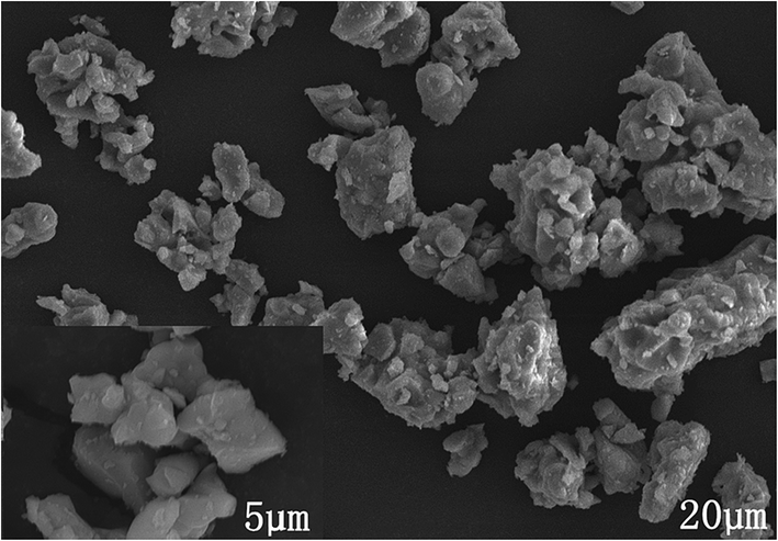
Fig. 2 displays the SEM image of Ca13.9Zn6Ga9.85O35:0.1Dy3+, 0.15Mn4+. The sample exhibits non-identical grains with the particle size approximately sub-micrometer to a few micrometers which tend to aggregate.
 |
| | Fig. 2 SEM image of Ca13.9Zn6Ga9.85O35:0.1Dy3+, 0.15Mn4+ sample. | |
3.2 High PL QEs of CZGO:Mn4+
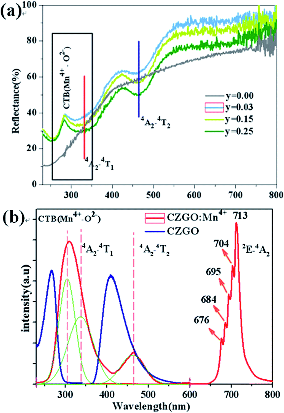
Fig. 3(a) shows the diffuse reflection spectra of Ca14Zn6Ga10−yO35:yMn4+ (y = 0.00, 0.03, 0.12, and 0.25). There are three dips of reflectivity between 280 and 550 nm. Two dips locating at 332 and 465 nm are assigned to strong spin-allowed transitions in Mn4+ ions corresponding to 4A2 → 4T2 and 4A2 → 4T1, respectively. The broad dip in the range of 250–350 nm is aroused by both Mn4+–O2− charge transfer transition and 4A2 → 4T1 transition of Mn4+ ions, which can be judged from the excitation spectra as below.
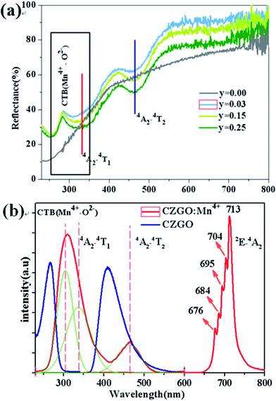 |
| | Fig. 3 (a) Representative diffuse reflection spectra of Ca14Zn6Ga10−yO35:yMn4+ (y = 0.00, 0.03, 0.12, 0.25). (b) PLE and PL of CZGO (λem = 410 nm, λex = 266 nm) and Ca14Zn6Ga9.99O35:0.01Mn4+ (λem = 713 nm, λex = 310 nm). | |
PLE and PL of CZGO (λem = 410 nm, λex = 266 nm) and Ca14Zn6Ga9.99O35:0.01Mn4+ (λem = 713 nm, λex = 310 nm) are shown in Fig. 3(b). For CZGO, an absorption band from about 200 nm to 300 nm centered at 266 nm (monitored emission wavelength λem = 410 nm) and a broad-band PL blue emission centered at 410 nm extend from 360 nm to 500 nm (excitation wavelength λex = 266 nm) of CZGO are observed. The broad-band blue emission has not been reported in CZGO before,19,20 but similar blue emission was observed in ZnGa2O4 crystals owning to the distorted octahedral Ga–O groups serving as the self-activated luminescent centers.23–27 It is reasonable to ascribe the broad-band blue emission to the recombination of a donor–acceptor pair (DAP) through a tunneling process in CZGO host. For Ca14Zn6Ga9.97O35:0.03Mn4+, the excitation spectrum can be fitted by three Gaussian curves, leading to three distinguished bands peaking at 303 (band I, 33![[thin space (1/6-em)]](https://www.rsc.org/images/entities/char_2009.gif) 003 cm−1), 332 (band II, 30120 cm−1) and 465 (band III, 21505 cm−1) which are in good agreement with those in the diffuse reflection spectra. The excitation bands located at 332 and 465 nm are assigned to the spin-allowed (4A2 → 4T2) and (4A2 → 4T1) transitions of Mn4+, respectively. The broad band, which is composed by bands I and II, is due to the overlap between the transitions of Mn4+–O2− and the spin-allowed transitions of Mn4+ (4A2 → 4T1). Under excitation at 310 nm, the intense red emission is composed of some distinguishable sharp R lines and Stokes/anti-Stokes side-peaks, located at 676, 684, 695, 704 and 713 nm, due to different vibrational modes for the 3d3 electrons when Mn4+ is of the octahedral complex.28 Although there is an overlap between the PLE spectrum of CZGO and Mn4+ ion, our measurement for the average lifetimes of the PL spectrum of CZGO with different Mn4+ concentration suggesting there is no energy transfer between CZGO and Mn4+.
003 cm−1), 332 (band II, 30120 cm−1) and 465 (band III, 21505 cm−1) which are in good agreement with those in the diffuse reflection spectra. The excitation bands located at 332 and 465 nm are assigned to the spin-allowed (4A2 → 4T2) and (4A2 → 4T1) transitions of Mn4+, respectively. The broad band, which is composed by bands I and II, is due to the overlap between the transitions of Mn4+–O2− and the spin-allowed transitions of Mn4+ (4A2 → 4T1). Under excitation at 310 nm, the intense red emission is composed of some distinguishable sharp R lines and Stokes/anti-Stokes side-peaks, located at 676, 684, 695, 704 and 713 nm, due to different vibrational modes for the 3d3 electrons when Mn4+ is of the octahedral complex.28 Although there is an overlap between the PLE spectrum of CZGO and Mn4+ ion, our measurement for the average lifetimes of the PL spectrum of CZGO with different Mn4+ concentration suggesting there is no energy transfer between CZGO and Mn4+.
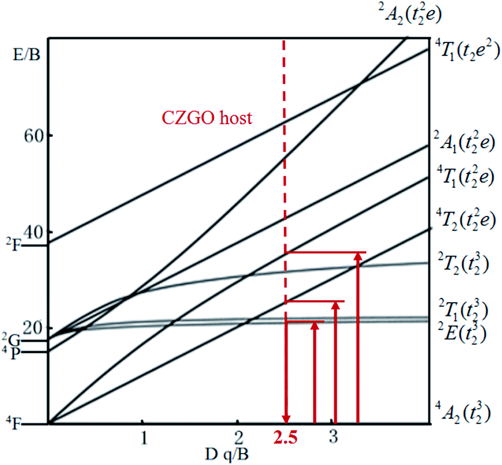
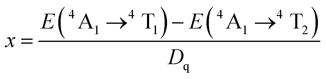
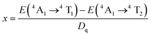
The energy splitting of Mn4+ ion with octahedral coordination on the crystal field strength can be well illustrated by Tanabe–Sugano energy diagram (Fig. 4).29 The value of the local crystal-field parameter Dq can be obtained from the peak energy (21505 cm−1) of the 4A2 → 4T2 transition30
| | |
Dq = E(4A2g → 4T2g)/10
| (1) |
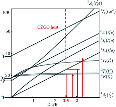 |
| | Fig. 4 Tanabe–Sugano diagram for Mn4+ in CZGO. | |
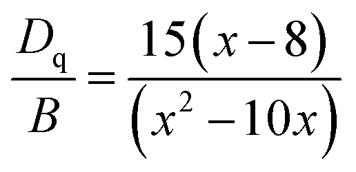
Moreover, based on the obtained energy difference (8615 cm−1) between the 4A2 → 4T2 and 4A2 → 4T1 transitions, Racah parameter B can be evaluated from the expression31
| |
 | (2) |
here the parameter
x is defined as
| |
 | (3) |
According to the peak energy (14025 cm−1) corresponding to 2E → 4A2 transition of Mn4+ derived from emission spectrum above, Racah parameter C can be calculated by the following eqn32
| | |
E(2E → 2A2)/B = 3.05C/B + 7.9 − 1.8B/Dq
| (4) |
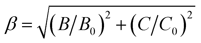
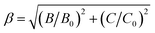
The values of Dq, B and C in the CZGO:Dy3+, Mn4+ are then determined to be 2150, 860 and 2572 cm−1, respectively. The values of B is higher than those reported in oxides while the values of C is smaller than those reported in oxides, and the values of Dq is similar to those reported in oxides.33 In fact, the emission peak energy of 2E → 4A2 transition is singularly dependent on the covalence of the “Mn4+–ligand” bonding (nephelauxetic effect). The nephelauxetic ratio β can be determined by following equation:34
| |
 | (5) |
here
B0 and
C0 represent Racah parameters for free ions. For Mn
4+ ions,
B0 and
C0 are equal to 1160 cm
−1 and 4303 cm
−1, respectively.
35 So
β for Mn
4+ in CZGO is calculated to be 0.952. This value is similar to those reported in oxides, but higher than those in fluorides, due to the more ionic Mn
4+–F
− bonding than Mn
4+–O
2− bonding.
36
Fig. 5 shows PL spectra (λex = 310 nm) of Ca14Zn6Ga10−yO35:yMn4+ phosphors as a function of y at room temperature. The PL intensity of Mn4+ ions increases with increased Mn4+ concentration, and concentration quenching occurs beyond y = 0.15. Photoluminescence internal and external quantum efficiency of Ca14Zn6Ga10−yO35:yMn4+ phosphors is measured in Table 1. The photoluminescence internal an external quantum efficiencies (QEs) reach 64.4% and 56.2% respectively when y = 0.15. Although the internal quantum efficiency of our sample is lower than the phosphor Sr2MgAl22O36:Mn4+ reported by Renping Cao,17 the external quantum efficiency of our sample has been the highest one according to our knowledge.
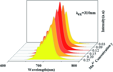 |
| | Fig. 5 Photoluminescence emission spectra of Ca14Zn6Ga10−yO35:yMn4+ (y = 0.03, 0.09, 0.12, 0.15, 0.20, 0.25) under λex = 310 nm. | |
Table 1 Photoluminescence internal and external QEs at different y in Ca14Zn6Ga10−yO35:yMn4+ phosphors excited at 310 nm
| y |
0.03 |
0.09 |
0.12 |
0.15 |
0.20 |
0.25 |
| Internal QE (%) |
41.3 |
49.5 |
59.4 |
64.4 |
54.6 |
44.6 |
| External QE (%) |
36.2 |
43.7 |
52.4 |
56.2 |
48.2 |
38.3 |
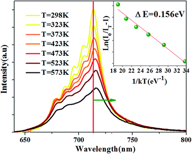
The temperature-dependent emission spectra is shown in Fig. 6, and two features can be observed: (1) emission intensity decreases with temperature increasing (2) all emission peaks shift to longer wavelength (red shift) region with increasing temperature.
 |
| | Fig. 6 PL spectra at different temperature for the Ca14Zn6Ga9.85O35:0.15Mn4+ excited at 310 nm. The inset: the activation energy 0.156 eV for Ca14Zn6Ga9.85O35:0.15Mn4+. | |
The Arrhenius equation can be used to evaluate activation energy ΔE for thermal quenching:37
| | |
IT = I0/[1 + cexp(−ΔE/kT)]
| (6) |
here
I0 is the initial emission intensity,
IT is the intensity at temperature
T,
c is a constant,
k is the Boltzmann constant, and Δ
E is the activation energy for thermal quenching. Based on the PL spectra in
Fig. 6, the Δ
E of CZGO:Mn
4+ is obtained as 0.156 eV by fitting the curve of ln[(
I0/
IT) − 1]
versus 1/
kT, as shown in the inset of
Fig. 6.
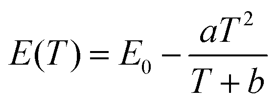
The peak position, the internal and external QEs are shown in Table 2. The peak position shifts from 713.4 to 716.6 nm as temperature from 298 K to 573 K. The red-shift behavior can be explained by the Varshini equation for temperature dependence38,39
| |
 | (7) |
where
E(
T) is the energy difference between excited states and ground states at a temperature
T,
E0 is the energy difference at 0 K, and
a and
b are fitting parameters. The bond lengths between the luminescent center and its ligand ions increase with increased temperature, which results in the decreased crystal field. Then, it will cause the split of degenerate excited state or ground state, resulting in the decrease of the transition energy. Therefore, the emission peak is red-shifted with the increase of temperature.
40 The red-shift behavior can also be explained by Tanabe–Sugano energy diagram (
Fig. 4), decreased crystal field correspond to less value of
Dq/
B, resulting in the smaller transition energy between excited state
2E and ground state
4A
2.
Table 2 The peak position, internal and external QEs of Ca14Zn6Ga9.85O35:0.15Mn4+ at different temperature
| Temperature (K) |
298 |
323 |
373 |
423 |
473 |
523 |
573 |
| Peak (nm) |
713.4 |
714.0 |
714.3 |
715.0 |
715.6 |
715.9 |
716.6 |
| Internal QE (%) |
64.4 |
63.7 |
61.4 |
59.4 |
56.4 |
53.0 |
45.9 |
| External QE (%) |
56.2 |
55.4 |
53.4 |
51.6 |
49.0 |
46.1 |
39.9 |
Both internal QE and external QE decreases with increased temperature. The internal and external QEs decrease 28.7% and 29.0% of the values at 298 K, respectively. Almost the same decreasing rate indicates that the change of QEs with temperature is not brought by the change of the absorption of the incident light on the phosphors.
3.3 White light of CZGO:Dy3+
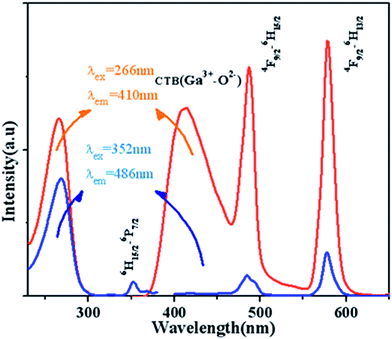
Fig. 7 displays the PL and PLE spectra of Ca13.9Zn6Ga10O35:0.1Dy3+ (λem = 410 nm and 486 nm, λex = 266 nm and 352 nm). The broad emission blue band centered at 410 nm is obviously from CTB of host. The absorption peak centered at 352 nm and the sharp emission bands centered at 486 nm and 578 nm come from the transition 6H15/2 → 6P7/2, 4F9/2 → 6H13/2 and 4F9/2 → 6H15/2 for Dy3+ ion respectively. It can be seen that the emission spectrum under the excitation 266 nm have the similar profile with that excited at 352 nm except for the appearance of the wide band centered at 410 nm. In addition to, the intensity of emission excited at 266 nm is much times higher than the emission excited at 352 nm, which indicating the high photon energy that host absorbed can be transferred efficiently to Dy3+ ion.
 |
| | Fig. 7 PL and PLE spectra of Ca13.9Zn6Ga10O35:0.1Dy3+ (λem = 410 nm and 486 nm, λex = 266 nm and 352 nm). | |
The dependence of the emission host intensities of Ca14−xZn6Ga10O35:xDy3+ phosphors on Dy3+ concentration x is shown in Fig. 8. The change of the intensity for 4F9/2 → 6H13/2, 6H15/2 transition shows the feature of concentration quenching with the maximum intensity as x = 0.1. However, the blue intensity for host decreases monotonically with x increase, indicating further the existence of the energy transfer from the host to Dy3+ ions.
 |
| | Fig. 8 Emission spectra of Ca14−xZn6Ga10O35:xDy3+ under the excitation of 266 nm. The inset shows the dependence of three emission peakshost on Dy3+ concentration. | |
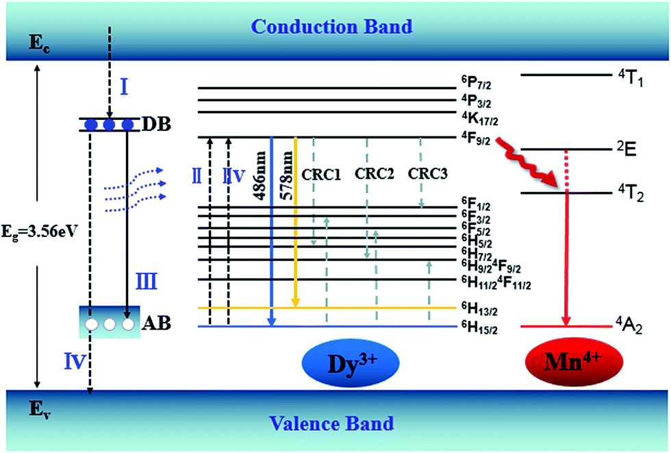
An energy band diagram is proposed in Fig. 9. The broad-band blue emission of host is suggested to be ascribed to the recombination of a donor–acceptor pair (DAP) through a tunneling process, that is, from the transition between electrons trapped by the donor band (DB) (being formed by oxygen vacancies) and holes captured by the acceptor band (AB) (being formed by gallium vacancy) (VGa), or pair of gallium vacancy and oxygen vacancy (VO, VGa). It is worth noting that the absorption energy (4.7 eV, 266 nm) of host is located at approximately twice the energy of the Dy3+:4F9/2 → 6H13/2 (2.1 eV, 578 nm) or 4F9/2 → 6H15/2 (2.5 eV, 486 nm) transition. Moreover, absorption bands of the host and Dy3+ are almost overlapped in Fig. 7, which means the energy transfer process from the host to Dy3+ is dominated by the cooperative energy transfer.41,42 The cooperative energy transfer between the CZGO host and Dy3+ ions can be understood as following: in first step, the electrons in the conduction band de-excite to DB (process I in Fig. 9), accompanying the excitation of Dy3+ from 6H15/2 to 4F9/2 (process II in Fig. 9) followed by the emission of Dy3+ (4F9/2 → 6H13/2 and 4F9/2 → 6H15/2); In second step, the electrons in DB can either de-excite to AB (process III in Fig. 9) which results the emission of the host, or to valance band (process IV in Fig. 9) which results the excitation of Dy3+ from 6H15/2 to 4F9/2 (process IIV in Fig. 9) followed by the emission of Dy3+. The concentration quenching of Dy3+ emission intensity can be ascribed to the cross relaxation between neighboring Dy3+ ions. Cross relaxation (CR) occurs when the energy from excited states promotes the ground state to the metastable levels. For Dy3+ ions, the CR mechanisms [4F9/2, 6H15/2] → [6H7/2/4F9/2, 6F3/2], [4F9/2, 6H15/2] → [6H9/2/6F11/2, 6F5/2] and [4F9/2, 6H15/2] → [6F1/2, 6H9/2/6F11/2] denoted by CRC1, CRC2, and CRC3, respectively, are possible responsible to the concentration quenching based on the energy match rule, as illustrated in Fig. 9.
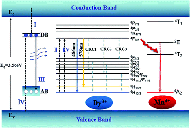 |
| | Fig. 9 Energy level diagram showing energy transfer and the CR processes of CZGO:Dy3+, Mn4+. | |
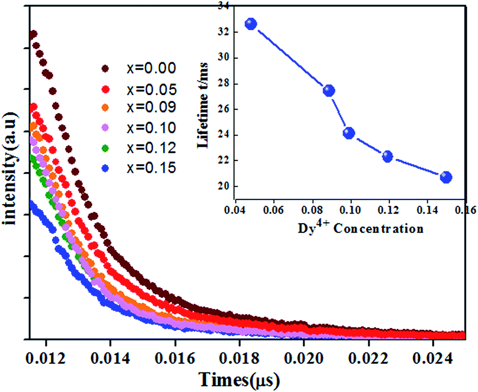
The fluorescence decay curves of Ca14−xZn6Ga10O35:xDy3+ (x = 0.00, 0.05, 0.09, 0.10, 0.12, 0.15) monitored at 410 nm with the excitation of 266 nm are shown in Fig. 11. The curve can be nearly fitted by one exponential function, and the average lifetime τ is given by43
| |
 | (8) |
where
I(
t) is the luminescent intensity at time
t. The obtained
τ is given in the inset of
Fig. 10. The lifetime decreased from 32.8 μs to 22.6 μs when the concentration of Dy
3+ increased from 0.05 to 0.15. The decrease of lifetime with increase of Dy
3+ concentration confirms the existence of the energy transfer between host and Dy
3+ ions.
 |
| | Fig. 10 Luminescence decay curves of Ca14−xZn6Ga9.88O35:xDy3+ (x = 0.00, 0.05, 0.09, 0.10, 0.12, 0.15) (monitored at 410 nm excited at 266 nm). The inset: dependence of the lifetime τ and energy transfer efficiency η on Dy3+ doping concentration. | |
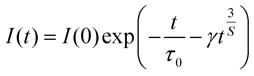
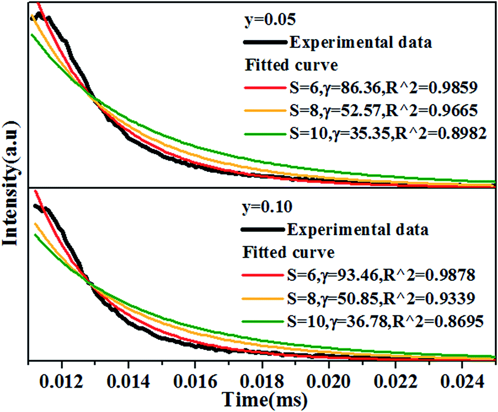
In order to figure out the interaction type of energy transfer between host and Dy3+ ions, the donor centers of oxygen vacancies marked as “A”, are considered. If “A” and Dy3+ ions are randomly distributed in the host and the migration processes among Dy3+ ions are negligible, then the temporal evolution of the Dy3+ luminescence intensity I(t), following pulsed excitation at 266 nm, can be given by the Inokuti–Hirayama (I–H) model44
| |
 | (9) |
where
I(0) is luminescence intensity when
t = 0,
τ0 is the lifetime of the host in the absence of Dy
3+ ions,
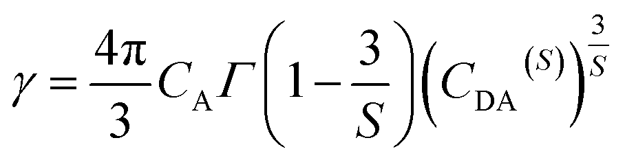
S is the multipolar interaction parameter, and the energy transfer parameter
γ is defined by
| |
 | (10) |
in which
CA is Dy
3+ concentration,
Γ(
x) is the gamma function, and
CDA(S) is the “A” → Dy
3+ energy transfer parameter. The decay curves for the samples doped with 5 mol% and 10 mol% of Dy
3+ ions are presented in
Fig. 11. The best fitting using I–H model is
S = 6, indicating the energy transfer between the host and Dy
3+ ions is dominantly governed by dipole–dipole interaction.
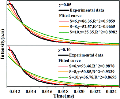 |
| | Fig. 11 Decay curves of Ca14−xZn6Ga10O35:xDy3+, (x = 0.05, 0.10) measured by 266 nm excitation and monitored at 410 nm, together with the fitted curves using I–H model, showing the best fitting when S = 6. All the experimental data of samples. | |
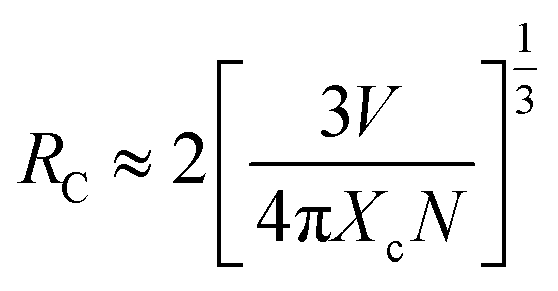
Considering no overlap between PLE and PL spectra of Dy3+, the concentration quenching of Dy3+ emission cannot be related to the radiation re-absorption. It might be attributed to multipole–multipole interaction or exchange interaction. In order to figure out this point, the average distance (Rc) between the nearest Dy3+ ions can roughly be calculated using the following eqn.45
| |
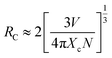 | (11) |
where
V is the volume of the unit cell;
N is the number of host cations which can be replaced by Dy
3+ ions in the unit cell;
Xc is the critical concentration of Dy
3+ ion. For this case,
V = 3428.88 Å
3,
N = 4,
Xc = 0.10,
Rc is obtained to be 25 Å. Blasse
46 has pointed out that multipolar interaction predominates if
Rc is larger than 5 Å. Therefore, the multipolar interaction accounts for the concentration quenching in CZGO:Dy
3+ phosphors.
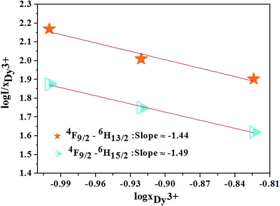
Based on the model proposed by Dexter,47 the interaction type between Dy3+ ions can be identified by
| | |
I/x = [1 + β(x)θ/3]−1
| (12) |
where
I is the emission intensity of Dy
3+ ion under the excitation of 352 nm;
x is Dy
3+ concentration; and is a constant for the same excitation condition for a given host.
θ = 6, 8, or 10 for dipole–dipole (d–d), dipole–quadrupole (d–q) and quadrupole–quadrupole (q–q), respectively. For the phosphor CZGO:Dy
3+, the dependence of log(
I/
xDy3+) on log(
xDy3+) shown in
Fig. 12 is almost linear and the fitted line slopes are −1.44 and −1.49 for
4F
9/2 →
6H
13/2 and
4F
9/2 →
6H
15/2 transition respectively. The value of
θ is 6 determined by the line slope, indicating the electric d–d interaction is responsible for the concentration quenching of Dy
3+ ions in CZGO.
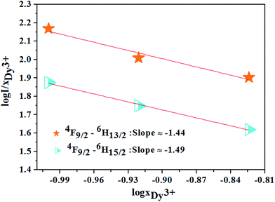 |
| | Fig. 12 The relations of log(I/xDy3+) and log(xDy3+) for 4F9/2 → 6H13/2, 4F9/2 → 6H15/2 transitions of Dy3+ ions. | |
3.4 Optimized white light of CAGO:Dy3+, Mn4+
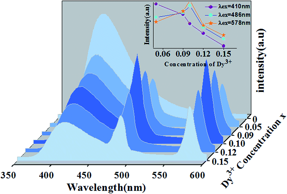
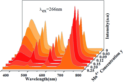
Fig. 13 shows PL spectra of Ca13.9Zn6Ga10−yO35:0.1Dy3+, yMn4+ phosphors (y = 0.03, 0.09, 0.12, 0.15, 0.20, 0.25) at room temperature (λex = 266 nm). The spectra exhibits blue CTB, blue/yellow emissions and a deep red emission, which result from the emission of host, 4F9/2 → 6H15/2/4F9/2 → 6H13/2 transitions of Dy3+ ion and 2E → 4A2 transition of Mn4+ ion, respectively. As Mn4+ concentration increases, the emissions intensity of both host and Dy3+ ions decrease, and the maximum emission of Mn4+ ions is shown as y = 0.15. As discussed above, energy transfer exists from host to Dy3+ ions at the excitation of 266 nm. Moreover, the external QEs of Mn4+ ion excited at 266 nm in Ca13.9Zn6Ga9.85O35:0.1Dy3+, 0.15Mn4+ and Ca14Zn6Ga9.85O35:0.15Mn4+ are measured as 15.6% and 10.1%, which indicating the energy transfer from Dy3+ to Mn4+ helps enhancing the QEs of Mn4+ emission. Energy transfer from Dy3+ to Mn4+ ions is also possible due to the overlap between the PLE spectrum of Mn4+ ions and PL spectrum of Dy3+ ions in CAGO:Dy3+, Mn4+. The energy transfer mechanism from Dy3+ to Mn4+ ion can be explained as non-radiative transitions from 4F9/2 level of Dy3+ (20747 cm−1) to 4T2 level of Mn4+ (14025 cm−1) by the assistance of phonons48 by Fig. 10. Therefore, multiply energy transfer can be happen in CZGO:Dy3+, Mn4+ at the excitation of 266 nm.
 |
| | Fig. 13 Photoluminescence emission spectra of Ca13.9Zn6Ga10−yO35:0.1Dy3+, yMn4+ as a function of y under λex = 266 nm. | |
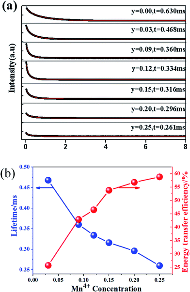
Fig. 14(a) shows the luminescence decay curves (excited at 266 nm and monitored at 486 nm of Dy3+ emission) of Ca13.9Zn6Ga10−yO35:0.1Dy3+, yMn4+ samples. The lifetimes were determined by the fitting of single exponential function to be 0.630, 0.468, 0.360, 0.334, 0.316, 0.296 and 0.261 ms for y = 0, 0.03, 0.09, 0.12, 0.15, 0.20, and 0.25 respectively, shown also in Fig. 14(a). The decrease of the lifetime confirms the existence of energy transfer from Dy3+ to Mn4+. The energy-transfer efficiency ηT is calculated using eqn (5) and shown in Fig. 14(b). Although the value of ηT always increase with increasing Mn4+ dopant concentration in our experiment, the emission intensity of Mn4+ tends to decrease at higher Mn4+ concentration (x > 0.15) due to the concentration quenching. The energy transfer efficiency is 59% when y = 0.25 with maximal 713 nm emission intensity.
 |
| | Fig. 14 (a) Decay curves of Ca13.9Zn6Ga10−yO35:0.1Dy3+, yMn4+ phosphors doped with various Mn4+ concentrations (excited at 266 nm and monitored at 486 nm). (b) The dependence of lifetime and energy transfer efficiency (corresponding to the Dy3+ 4F9/2 → 6H15/2 transition) in Ca13.9Zn6Ga10−yO35:0.1Dy3+, yMn4+ (y = 0.05, 0.09, 0.12, 0.15, 0.20, 0.25) on Mn4+ concentration. | |
According to Dexter's energy-transfer model of multipolar interaction and Reisfeld's approximation, the following relation can be given 49,50
| |
 | (13) |
where
τDy and τ
Dy–Mn are the lifetimes of Dy
3+ in the absence and presence of Mn
4+, respectively.
C is the sum of the concentrations of Dy
3+ and Mn
4+, and
S = 6, 8 and 10 corresponding to d–d, d–q, and q–q interactions, respectively.
Fig. 15 shows the linear fitting of the relationship between
τDy/
τDy-Mn and
CS/3, and the largest values of
R2 with
S = 6, indicating that the energy transfer from Dy
3+ to Mn
4+ occurs
via d–d interaction.
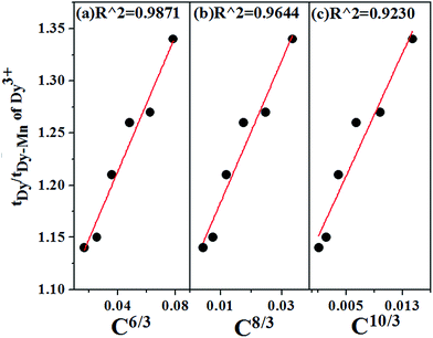 |
| | Fig. 15 Dependence of τDy/τDy−Mn on (a) C6/3, (b) C8/3 and (c) C10/3 in Ca13.9Zn6Ga10−yO35:0.1Dy3+, yMn4+ (y = 0.05, 0.09, 0.12, 0.15, 0.20, 0.25). The best linear fitting indicates the energy transfer from Dy3+ to Mn4+ occurs via d–d interaction. | |
Fig. 16 shows the CIE chromaticity diagram of (a) CZGO, (b) Ca13.9Zn6Ga10O35:0.1Dy3+, (c) Ca13.9Zn6Ga9.85O35:0.1Dy3+, 0.15Mn4+ excited at 266 nm and (d) Ca14Zn6Ga9.85O35:0.15Mn4+ excited at 310 nm. The phosphor CZGO emits deep blue light, of which the chromaticity coordinate is (0.158, 0.062). The chromaticity coordinates of Ca13.9Zn6Ga10O35:0.1Dy3+ and Ca13.9Zn6Ga9.85O35:0.1Dy3+, 0.15Mn4+ with CCTs of 5252 K and 3522 K, with CRIs of 72 and 87, are (0.254, 0.288) and (0.345, 0.275), respectively. Obviously, higher color rendering index (CRI) and lower color temperature are obtained by adding Mn4+ ions. Except for the short exciting wavelength, the high color rendering index (Ra = 87) and low color temperature 3522 K can well meet the generally lighting.
 |
| | Fig. 16 CIE chromaticity coordinates of (a) CZGO, (b) Ca13.9Zn6Ga10O35:0.1Dy3+, (c) Ca13.9Zn6Ga9.85O35:0.1Dy3+, 0.15Mn4+ excited at 266 nm and (d) Ca14Zn6Ga9.85O35:0.15Mn4+ excited at 310 nm in wavelength range 380–800 nm. | |
4 Conclusion
In summary, strong blue emission band ranging from 370 nm to 500 nm was observed for CZGO host, attributed to the recombination of a donor–acceptor pair (DAP) through a tunneling process. The highest internal and external quantum efficiencies were measured to be 64.4% and 56.2% respectively for CZGO:Mn4+. This external quantum efficiency is the highest one reported for Mn4+ doped oxides. The energy transfer processes either from the host to Dy3+ or from Dy3+ to Mn4+ are confirmed and demonstrated arising from dipole–dipole interaction in Dy3+/Mn4+ co-doped CZGO, and the emission changes from deep blue to white to deep red according to the different Dy3+/Mn4+ concentration ratio, and Furthermore, the warm white emission can be realized with the chromaticity coordinate (0.345, 0.275), CCT 3525 K and CRI 87. The results suggest CZGO:Mn4+ phosphors have the potential application as high efficiency red phosphors for solid-state lighting, while Dy3+/Mn4+ co-doped CZGO can used as a single-phased white phosphor.
Acknowledgements
Financial supported from the Key Laboratory of Innovation Method and Decision Management System of Guangdong Province, the Research Guangzhou Science (No. 2016201604030035) and Technology Project of Guangdong Province, China (No. 2016201604030027).
References
- J. H. Chen, W. R. Zhao, N. H. Wang, Y. J. Meng, S. P. Yi, J. He and X. Zhang, J. Mater. Sci., 2016, 51, 4201–4212 CrossRef CAS.
- Y. H. Jin, Y. R. Fu, Y. H. Hu, L. Chen, H. Y. Wu, G. F. Ju, M. He and T. Wang, Powder Technol., 2016, 292, 74–79 CrossRef CAS.
- T. Murata, T. Tanoue, M. Iwasaki, K. Morinaga and T. Hase, J. Lumin., 2005, 114, 207–212 CrossRef CAS.
- M. G. Brik, Y. X. Pan and G. K. Liu, J. Alloys Compd., 2011, 509, 1452–1456 CrossRef CAS.
- A. A. Setlur, E. V. Radkov, C. S. Henderson, J.-H. Her, A. M. Srivastava, N. Karkada, M. S. Kishore, N. P. Kumar, D. A. Esram, A. Deshpande, B. Kolodin, L. S. Grigorov and U. Happek, Chem. Mater., 2010, 2, 4076–4082 CrossRef.
- G. B. Loutts, M. Warren, L. Taylor, R. R. Rakhimov, H. R. Ries, G. Miller III, M. A. Curley, N. Noginova, N. Kukhtarev, H. J. Caulfeld and P. Venkateswarlu, Phys. Rev. B: Condens. Matter Mater. Phys., 1998, 57, 3706 CrossRef CAS.
- Y. Zhydachevskii, D. Galanciak, S. Kobyakov, M. Berkowski, A. Kaminska, A. Suchocki, Y. Zakharko and A. Durygin, J. Phys.: Condens. Matter, 2006, 18, 11385–11396 CrossRef CAS.
- Y. Zhydachevskii, A. Durygin, A. Suchocki, A. Matkovskii, D. Sugak, P. Bilski and S. Warchol, Nucl. Instrum. Methods Phys. Res., Sect. B, 2005, 227, 545–550 CrossRef CAS.
- T. Arai and S. Adachi, Jpn. J. Appl. Phys., 2011, 50, 092401 Search PubMed.
- H. M. Zhu, C. C. Lin, W. Q. Luo, S. T. Shu, Z. G. Liu, Y. S. Liu, J. T. Kong, E. Ma, Y. G. Cao, R. S. Liu and X. Y. Chen, Nat. Commun., 2014, 5, 4312 CAS.
- T. Takahashi and S. Adachi, J. Electrochem. Soc., 2008, 155, 183–188 CrossRef.
- M. H. Du, J. Mater. Chem. C, 2014, 2, 2475 RSC.
- M. G. Brik and A. M. Srivastava, J. Lumin., 2013, 133, 69–72 CrossRef CAS.
- M. Y. Peng, X. W. Yin, P. A. Tanner, C. Q. Liang, P. F. Li, Q. Y. Zhang and J. R. Qiu, J. Am. Ceram. Soc., 2013, 96, 2870–2876 CrossRef CAS.
- L. Wang, L. Yuan, Y. Xu, R. Zhu, B. Y. Qu, N. Ding, M. Shi, B. Zhang, Y. Chen, Y. Jiang, D. Wang and J. Shi, Appl. Phys. A, 2014, 117, 1777–1783 CrossRef CAS.
- B. Wang, H. Lin, J. Xu, H. Chen and Y. Wang, ACS Appl. Mater. Interfaces, 2014, 6, 22905–22913 CAS.
- R. Cao, M. Peng, E. Song and J. Qiu, ECS J. Solid State Sci. Technol., 2012, 1, 123–126 CrossRef.
- K. Seki, K. Uematsu, K. Toda and M. Sato, Chem. Lett., 2014, 43, 1213–1215 CrossRef CAS.
- X. Y. Sun, M. Gu, S. M. Huang, X. L. Liu, B. Liu and C. Ni, Phys. B, 2009, 404, 111–114 CrossRef CAS.
- S. Y. Istomin, S. V. Chernov, E. V. Antipov and Yu. A. Dobrovolsky, J. Solid State Chem., 2007, 180, 1882–1888 CrossRef CAS.
- I. D. Brown, The Chemical Bond in Inorganic Chemistry. The Bond Valence Model, IUCr Monographs on Crystallography, Oxford University Press, 2002 Search PubMed.
- R. D. Shannon, Acta Crystallogr., Sect. A: Cryst. Phys., Diffr., Theor. Gen. Crystallogr., 1976, 32, 751–767 CrossRef.
- Y. E. Lee, D. P. Norta, C. Park and C. M. Roulean, J. Appl. Phys., 2001, 89, 1653–1655 CrossRef CAS.
- K. W. Chang and J. J. Wu, J. Phys. Chem. B, 2005, 109, 13572–13577 CrossRef CAS PubMed.
- L. E. Shea, R. K. Datta and J. J. Brown Jr, J. Electrochem. Soc., 1994, 141, 1950–1954 CrossRef CAS.
- I. K. Jeong, H. L. Park and S. I. Mho, Solid State Commun., 1998, 105, 179–183 CrossRef CAS.
- J. S. Kim, H. I. Kang, W. Kim, N. J. I. Kim, J. C. Choi, H. L. Park, G. C. Kim, T. W. Kim, Y. H. Hwang, S. I. Mho, M. C. Jung and M. Han, Appl. Phys. Lett., 2003, 82, 2029–2042 CrossRef CAS.
- A. M. Srivastava and W. W. Beers, J. Electrochem. Soc., 1996, 143, L203–L205 CrossRef CAS.
- Y. Tanabe and S. Sugano, J. Phys. Soc. Jpn., 1954, 9, 766–779 CrossRef CAS.
- M. J. Reisfeld, N. A. Matwiyof and L. B. Aspery, J. Mol. Spectrosc., 1971, 39, 8–20 CrossRef CAS.
- B. Henderson and G. F. Imbusch, Optical Spectroscopy of Inorganic Solids, Clarendon Press, Oxford, UK, 1984 Search PubMed.
- M. G. Brik and A. M. Srivastava, ECS J. Solid State Sci. Technol., 2013, 2, 148–152 CrossRef.
- Y. H. Jin, T. H. Hu, H. Y. Wu, H. Duan, L. Chen, Y. R. Fu, D. F. Ju, Z. F. Mu and M. He, Chem. Eng. J., 2016, 288, 596–607 CrossRef CAS.
- P. Uylings, A. Raassen and J. Wyart, J. Phys. B: At. Mol. Phys., 1984, 17, 4103–4126 CrossRef CAS.
- M. G. Brik and A. M. Srivastava, Ion in Solids, J. Lumin., 2013, 133, 69–72 CrossRef CAS.
- V. Bachmann, A. Meijerink and C. Ronda, J. Lumin., 2009, 129, 1341–1346 CrossRef CAS.
- Z. G. Xia and R. S. Liu, J. Phys. Chem. C, 2012, 116, 15604–15609 CAS.
- Y. P. Varshni, Physica, 1967, 34, 149–154 CrossRef CAS.
- J. S. Kim, Y. H. Park, S. M. Kim, J. C. Choi and H. L. Park, Solid State Commun., 2005, 133, 445–448 CrossRef CAS.
- Y. L. Huang, J. H. Gana, R. Zhua, X. G. Wang and H. J. Seo, J. Electrochem. Soc., 2011, 158, 334–J340 CrossRef.
- W. R. Wang, A. F. Zou, X. Lei, H. P. Gao and Y. L. Mao, Opt. Mater., 2014, 38, 261–264 CrossRef CAS.
- Q. Y. Zhang and C. F. Yang, Appl. Phys. Lett., 2007, 91, 051903 CrossRef.
- P. I. Paulose, G. Jose, V. Thomas, N. V. Unnikrishnan and M. K. R. Warrier, J. Phys. Chem. Solids, 2003, 64, 841–846 CrossRef CAS.
- I. R. Martín, V. D. Rodríguez, U. R. Rodríguez-Mendoza, V. Lavín, E. Montoya and D. Jaque, J. Chem. Phys., 1999, 111, 1191 CrossRef.
- G. Blasse, Phys. Lett. A, 1968, 28, 444–445 CrossRef CAS.
- G. Blasse, Philips Res. Rep., 1969, 24, 131 CAS.
- D. L. Dexter and J. H. Schulman, J. Chem. Phys., 1954, 22, 1063–1069 CrossRef CAS.
- Z. Xia, Y. Zhang, M. S. Molokeev and V. V. Atuchin, J. Phys. Chem. C, 2013, 117, 20847–20854 CAS.
- D. L. Dexter and J. H. Schulman, J. Chem. Phys., 1954, 22, 1063–1070 CrossRef CAS.
- R. Reisfeld and N. L. Soffer, J. Solid State Chem., 1979, 28, 391–395 CrossRef CAS.
|
| This journal is © The Royal Society of Chemistry 2017 |
Click here to see how this site uses Cookies. View our privacy policy here. 
 Open Access Article
 This Open Access Article is licensed under a Creative Commons Attribution-Non Commercial 3.0 Unported Licence
 ,
Weiren Zhao*,
Junhua Chen and
Zifeng Liao
,
Weiren Zhao*,
Junhua Chen and
Zifeng Liao