 Open Access Article
Creative Commons Attribution 3.0 Unported Licence
Facile synthesis of mesoporous graphene platelets with in situ nitrogen and sulfur doping for lithium–sulfur batteries†
Xiqing Yuana,
Bingchuan Liua,
Huijie Houa,
Kemal Zeinua,
Yuhang Hea,
Xiaorong Yanga,
Weijun Xuea,
Xiulin Hea,
Long Huanga,
Xiaolei Zhua,
Longsheng Wua,
Jingping Hu *a,
Jiakuan Yang
 *a and
Jia Xieb
aSchool of Environmental Science and Engineering, Huazhong University of Science and Technology (HUST), Wuhan, 430074, PR China. E-mail: hujp@hust.edu.cn; jkyang@hust.edu.cn; Fax: +86-27-87792101; Tel: +86-27-87793948
bSchool of Electrical & Electronic Engineering, Huazhong University of Science and Technology (HUST), Wuhan, 430074, PR China
First published on 25th April 2017
Abstract
The interaction between lithium polysulfides and doped heteroatoms could prevent the loss of soluble polysulfides in the cathode and mitigate the shuttle effect in lithium–sulfur batteries. Herein, a facile synthesis of mesoporous graphene platelets (NSGs) with in situ nitrogen and sulfur doping by the pyrolysis of a self-assembled L-cysteine precursor on sodium chloride crystal surface for structure-directing is presented. The mesoporous lamellar structure of the NSG possesses a uniform distribution of pyrrolic N, pyridinic N, and thiosulphate structured heteroatoms originating from in situ doping, which promotes the confinement of intermediate polysulfides. Combining the strong interactions with soluble polysulfide, flexible mesoporous architecture, and high conductivity of graphene, the prepared NSG material exhibited a high initial capacity of 1433 mA h g−1 at a 2C rate as well as a reversible capacity of 684 mA h g−1 after 200 cycles. This demonstrates that the in situ nitrogen and sulfur doped thin lamellar structure of graphene would be a promising cathode material for high performance lithium–sulfur batteries.
Introduction
The wide application of electric vehicles, grid energy storage and portable electronics has boosted the demand in the research and development of high energy density devices.1–3 Among them, lithium–sulfur (Li–S) battery is one of the most promising candidates for next generation high-performance secondary batteries due to the high theoretical capacity of 1675 mA h g−1, energy density of 2600 W h kg−1 and natural abundance of sulfur.4–6 But the commercial application of Li–S batteries is hindered by several inherent issues, including the poor electrical conductivity of sulfur, the large volume expansion (about 80%) during the charge process, and the loss of active mass in the cathode due to the dissolution of lithium polysulfides in the electrolyte and the shuttle effect.7–9Extensive research has been conducted to prepare different structures of carbon materials to encapsulate sulfur,10 including mesoporous carbon,11 carbon nanotube,12 carbon nanofiber13 and graphene,14 which has demonstrated the potential to improve the electrical conductivity and mitigate the dissolution of polysulfides and the shuttle effect. Among the carbon materials for Li–S batteries, graphene is a promising candidate because of its high electron mobility, good chemical stability, and super hydrophobicity at nanometer scale.15–17 Graphene synthesized from chemical vapor deposition (CVD),18 electrolytic exfoliation of graphite19 and reduction of graphene oxide20–22 has been utilized in Li–S batteries. However, the current fabrication processes are complicated, time-consuming, and costly, which involved toxic chemicals and corrosive acid. Therefore, it is highly desired to develop a facile and green method to prepare novel porous graphene materials on an easily processed template with unique structure for enhanced electrochemical performance.
Besides the development of novel carbon structures, the introduction of polysulfide affinitive heteroatoms on carbon materials by doping has attracted much attention in the preparation of sulfur cathodes for Li–S batteries23,24 by taking advantage of the strong attraction between lithium polysulfides and doped active sites on these carbon materials.25 Recently, silk fibroin protein had been used to produce porous nitrogen-doped carbon material for Li–S batteries.26 The cathode had a capacity retention of 98% at 1C after 200 cycles, which was partially attributed to the nitrogen doping for the adsorption of polysulfides. Xie et al. prepared a boron-doped 3D graphene aerogel via a one-pot hydrothermal treatment process.27 The electrochemical performance improved considerably because boron was positively polarized on the graphene framework, providing chemical adsorption sites for negative polysulfides. 3D coral-like nitrogen–sulfur co-doped carbon was synthesized by a novel hydrothermal-nanocasting method to house sulfur for Li–S batteries.28 The co-doping of nitrogen and sulfur enabled the carbon matrix to mitigate the diffusion of polysulfides. Therefore, it is believed that heterogeneous doping of carbon material can improve the electrochemical performance of Li–S batteries through enhanced interaction between polar functional group and polysulfide.29–31 However, further progress is still imperative on the design and synthesis of novel carbon materials with regard to the following aspects: (i) homogeneous distribution of heteroatoms, ideally in situ doping from precursor during synthesis; (ii) a thin, flexible and very conductive mesoporous structure used for sulfur host with easily accessible pores for lithium ions and provided a facile electron pathway; (iii) an easily manageable template that can be processed at mild conditions.
In the present work, we synthesized nitrogen and sulfur doped graphene platelet (NSG) by in situ doping through a novel method using L-cysteine as carbon precursor on water soluble salt which acted as a template. L-Cysteine is rich in sulfur and nitrogen in the form of thiol and amine groups which can be easily polymerized with its carboxylic group. The carbon material is presumed to exhibit high electrical conductivity and abundant nitrogen and sulfur containing active sites. The electrochemical performance of the hybrid cathode was investigated, and the composite delivered a high rate capacity and excellent cycling stability for application in Li–S batteries.
Experimental
Synthesis of N,S co-doped graphene platelet
Typically, L-cysteine (1 g) and NaCl (15 g) were added to deionized water (200 mL). After stirring for 12 h, the solution was frozen in a refrigerator at −28 °C for 48 h. The solid mixture was then freeze-dried (FD-1-50 freeze dryer, Biocool, China) to remove water content. The dried Cys–NaCl mixture was ground to obtain a uniform powder, which was heated at 800 °C for 2 h with a heating rate of 5 °C min−1 in N2 gas (100 sccm flow rate) to produce Cys–NaCl-800 composites. Subsequently, the NaCl template was dissolved by rinsing with hot distilled water for several times. The obtained sample was further pyrolyzed at 1000 °C for 3 h. After that, the final NSG (around 40 mg) was cooled down to room temperature and collected after grinding.Preparation of carbon–sulfur composites
The N,S co-doped graphene platelet was mixed with sulfur in the mass ratio of mS![[thin space (1/6-em)]](https://www.rsc.org/images/entities/char_2009.gif) :
:![[thin space (1/6-em)]](https://www.rsc.org/images/entities/char_2009.gif) mC = 3
mC = 3![[thin space (1/6-em)]](https://www.rsc.org/images/entities/char_2009.gif) :
:![[thin space (1/6-em)]](https://www.rsc.org/images/entities/char_2009.gif) 1. The mixture was sealed in a stainless steel container and kept at 155 °C for 12 hours to impregnate the pores with sulfur, followed by another heat treatment in a tube furnace at 300 °C for 2 hours under N2 atmosphere to remove excess sulfur on the carbon surface.
1. The mixture was sealed in a stainless steel container and kept at 155 °C for 12 hours to impregnate the pores with sulfur, followed by another heat treatment in a tube furnace at 300 °C for 2 hours under N2 atmosphere to remove excess sulfur on the carbon surface.
Preparation of cathode
The carbon–sulfur composite, super P carbon, and polyvinylidene fluoride (80![[thin space (1/6-em)]](https://www.rsc.org/images/entities/char_2009.gif) :
:![[thin space (1/6-em)]](https://www.rsc.org/images/entities/char_2009.gif) 10
10![[thin space (1/6-em)]](https://www.rsc.org/images/entities/char_2009.gif) :
:![[thin space (1/6-em)]](https://www.rsc.org/images/entities/char_2009.gif) 10) were ground in a mortar for 40 minutes using n-methyl-2-pyrrolidinone as the solvent, then the slurry was coated on an Al foil, pressed tight with a roller machine and then polished with a blade. The foil was dried at 50 °C for 6 hours in a vacuum oven, and hand punched into disks of a diameter of 8 mm. A sulfur loading of around 2.2 mg cm−2 was used in all the experiments.
10) were ground in a mortar for 40 minutes using n-methyl-2-pyrrolidinone as the solvent, then the slurry was coated on an Al foil, pressed tight with a roller machine and then polished with a blade. The foil was dried at 50 °C for 6 hours in a vacuum oven, and hand punched into disks of a diameter of 8 mm. A sulfur loading of around 2.2 mg cm−2 was used in all the experiments.
Electrochemical measurements
Lithium foil with a diameter of 16 mm was used as the anode, and a commercial polypropylene separator (Celgard 2400) was used as the separator. A mixture of 1 M lithium bistrifluoromethanesulfonylimide (LiTFSI) and 0.2 M LiNO3 dissolved in 1,3-dioxolane (DOL) and 1,2-dimethoxyethane (DME) (1![[thin space (1/6-em)]](https://www.rsc.org/images/entities/char_2009.gif) :
:![[thin space (1/6-em)]](https://www.rsc.org/images/entities/char_2009.gif) 1 by volume) was used as the electrolyte. Electrolyte of 90 μL for a cell was used to infiltrate the positive cathode fully during the fabrication. Coin cells (2032) were fabricated in an argon-filled glove box and cycled between 2.8 and 1.7 V (vs. Li+/Li) at 26 °C using a battery test system (LAND CT2001A, China). Cyclic voltammetry (CV) was carried out by potential cycling between 3 V and 1.5 V with a sweeping rate of 0.2 mV s−1, and electrochemical impedance spectroscopy (EIS) measurement was conducted in the frequency range of 100 kHz to 100 mHz with an AC amplitude of 5 mV using an electrochemical workstation (Biologic, VSP 300, France).
1 by volume) was used as the electrolyte. Electrolyte of 90 μL for a cell was used to infiltrate the positive cathode fully during the fabrication. Coin cells (2032) were fabricated in an argon-filled glove box and cycled between 2.8 and 1.7 V (vs. Li+/Li) at 26 °C using a battery test system (LAND CT2001A, China). Cyclic voltammetry (CV) was carried out by potential cycling between 3 V and 1.5 V with a sweeping rate of 0.2 mV s−1, and electrochemical impedance spectroscopy (EIS) measurement was conducted in the frequency range of 100 kHz to 100 mHz with an AC amplitude of 5 mV using an electrochemical workstation (Biologic, VSP 300, France).
Characterizations
Scanning electron microscopy (SEM) measurements were performed using FEI Nova NanoSEM 450 operated at an acceleration voltage of 10 kV after coating the samples with a very thin layer of gold to eliminate charging effect, and energy dispersive X-ray spectroscopy (EDX) spectra were acquired at an acceleration voltage of 20 kV. Transmission electron microscopy (TEM) images were acquired using Tecnai G2 F30 (Netherlands). Brunauer–Emmett–Teller (BET) type nitrogen adsorption isotherm measurements were conducted using automatic specific surface area and porosity analyzer (JW-BK122W, JWGB LTD., China). The crystalline structure was identified by X-ray diffraction analysis (XRD, D/MAX 2550, Rigaku, Japan) using Cu Kα radiation (λ = 1.54 Å), with an operation voltage of 40 kV and current of 300 mA. Thermal gravity analysis (TGA) was performed using TA SDT Q600, with a heating rate of 10 °C min−1. Raman measurements were performed using a Jobin Yvon LabRAM HR800, excited by a 632.8 nm He–Ne laser. X-ray photoelectron spectroscopy (XPS) measurements (GENESIS, American) were performed to analyze the surface chemistry of the material, and analyzed quantitatively using CasaXPS software.Computational details
The simulation was conducted using Dmol3 package in Materials Studio 8.0 software. Geometry optimization calculations were performed under the generalized gradient approximation (GGA) using the Perdew–Burke–Ernzerhof (PBE) exchange–correlation function. A double numerical basis with polarization (DNP) as well as effective core potential (ECP) were adopted for a large supercell (5 × 5) of graphene, and the self-consistent field tolerance was set to 10−5 Ha.Results and discussion
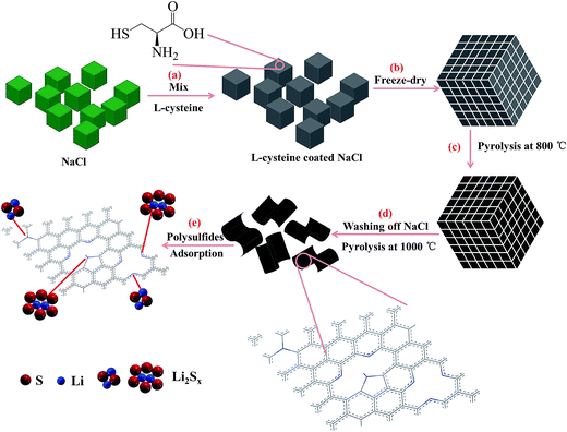
The synthesis of N,S co-doped graphene platelet was carried out by pyrolysizing L-cysteine on NaCl crystal template (Scheme 1). After freeze-drying, cysteine molecules were assembled on NaCl crystal surface, which acted as a template for the subsequent formation of 2D carbon structure. During pyrolysis, the assembled cysteine was polymerized, aromatized and carbonized on the surface of NaCl crystals, followed by washing off the NaCl template and a further pyrolysis at high temperature to obtain graphene platelet.The produced graphene platelet material using a NaCl template exhibited an entangled sheet-like morphology as shown in SEM and TEM images in Fig. 1a and c. TEM results showed that the NSG was very thin and exhibited typical corrugated structure (Fig. 1c), which was beneficial for the enhanced performance of Li–S batteries.32–34 From the EDX results (Fig. 1b), the presence of C, O, N, and S can be observed, together with a weak Au signal originated from the sample pre-treatment. The sodium or chloride signal was not discernible in the EDX spectrum, indicating the complete removal of NaCl template by simply rinsing with water during synthesis. EDX mapping revealed that the NSG was doped with N and S elements, and nitrogen and sulfur were not homogeneously distributed (Fig. 2d–g). The mild processing condition was beneficial to mitigate excess defects introduced in the honeycomb structure of graphene, considering that the lots of defects were detrimental to the electrical conductivity. The atomic contents of nitrogen and sulfur were almost identical, in agreement with the stoichiometry of thiol and amine groups in L-cysteine (HO2CCH(NH2)CH2SH), implying that N and S elements were successfully doped in the NSG. The in situ nitrogen and sulfur co-doping was derived from the polycondensation reaction between thiol and amine groups and between carboxylic group and amine groups of L-cysteine during pyrolysis, leading to the formation of some residual C–S and C–N bonds in the graphene framework that partially survived from the pyrolysis treatment.
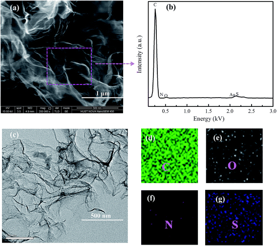 | ||
| Fig. 1 (a) and (c) SEM and TEM images of NSG, (b) elemental analysis, (d) C, (e) O, (f) N and (g) S elemental mapping of the selected region by EDX. | ||
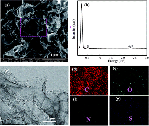 | ||
| Fig. 2 (a) and (c) SEM and TEM images of the NSG/S composite, (b) elemental analysis, (d) C, (e) O, (f) N and (g) S elemental mapping of the selected region by EDX. | ||
After a facile melting–diffusion and infiltration treatment, the composite of NSG and sulfur was obtained as shown in the SEM and TEM images (Fig. 2). No discernible morphology changes were observed after loading with sulfur and further heat treatment at 300 °C, indicating no excess sulfur debris at the exterior surface of NSG (Fig. 2a). EDX mapping revealed that the NSG/S composite was doped with N and S elements, and nitrogen and sulfur were homogeneously distributed throughout the NSG/S composite (Fig. 2d–g). The uniform distribution of N and S could be attributed to the inherent origination of dopant from the L-cysteine precursor. Sulfur was uniformly distributed inside the pores, which can be confirmed by the TEM images in Fig. 2c. The well dispersion of sulfur inside the mesopores of NSG was critical for improving the performance of Li–S batteries.35–37
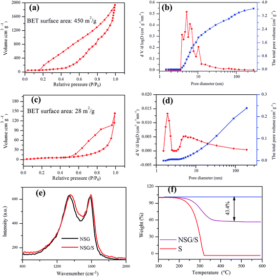
The N2 adsorption–desorption isotherms, pore size distribution and the total pore volume curves of the NSG and NSG/S composite were derived from BET measurements to validate the presence of mesopores in the materials (Fig. 3a–d). After sulfur incorporation in NSG, the BET surface area of NSG (450 m2 g−1) decreased to 28 m2 g−1, and the total pore volume of NSG/S composite also decreased from 3.6 cm3 g−1 to 0.24 cm3 g−1, indicating that the sulfur was infused into the pores of NSG. The high surface area of NSG was attributed to the assembling of 2D graphene structure on the NaCl crystal template, which produced very thin and wrinkled layers with abundant pores. However, the surface area of NSG was much lower than the theoretical value of single-layered graphene,38 probably due to the few-layered structure and stacking of interlayers induced by strong π–π interaction.
The degree of graphitization of the NSG and the NSG/S mixture was evaluated using Raman spectroscopy (Fig. 3e). The ID/IG ratio of the NSG was 1.019, suggesting the presence of defects in NSG and a sufficient degree of graphitization for high electrical conductivity39,40 which was especially beneficial to retain a high rate capacity. After the infusion of sulfur, the ID/IG ratio in Raman spectra decreased slightly to 1.003, indicating little change in microstructure during sulfur encapsulation, which was beneficial for the stability of batteries. In the meantime, the weight content of sulfur in the NSG/S composite was evaluated by TGA (Fig. 3f) and the sulfur loading in the NSG/S mixture was estimated to be 43.4%, which was adopted for the calculation of battery capacities.
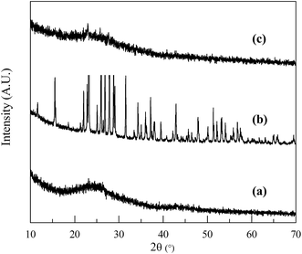
The crystal structures of NSG, sulfur and the NSG/S mixture were analyzed using XRD (Fig. 4). The XRD spectra of NSG exhibits a broad diffraction peak at 25° (Fig. 4a) which can be associated with partially graphitized carbon.41 After encapsulation of sulfur inside the pores of mesoporous sheets, the sulfur peaks became much weaker (Fig. 4c), confirming the incorporation of well dispersed sulfur inside the pores.
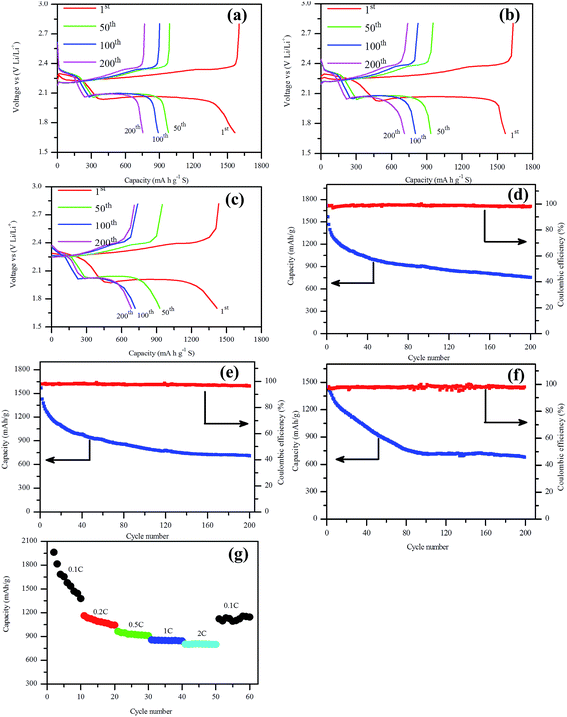
The charge–discharge test of assembled Li–S battery was carried out to evaluate the electrochemical performance of this NSG/S composite, as shown in Fig. 5. From the charge–discharge profiles of the batteries (Fig. 5a–c), it can be observed that the discharge capacity of the first cycle at 0.5C, 1C and 2C are 1603 mA h g−1, 1635 mA h g−1, and 1433 mA h g−1 respectively, and the cathode convertible capacity retained at 889 mA h g−1, 803 mA h g−1 and 716 mA h g−1 after 100 cycles, implying a good cycling stability of the batteries at high current rate (2C). The discharge capacity of the first cycle at 0.5C slightly lower than that of the result at 1C is most likely attributable to different sulfur loadings, 2.25 mg cm−2 and 2.11 mg cm−2 respectively. As we all know, the electrochemical performance of the batteries deteriorated with the increasing sulfur loading in the Li–S batteries due to the increased concentration polarization of polysulfides in the cathode.42 It is apparent that there are two discharge plateaus and a single charge plateau, corresponding to the peaks in the cyclic voltammogram. The two discharge plateaus were related to the reduction peaks and the charge plateau was related to the oxidation peak. Meanwhile, these two plateaus in the discharge curves maintained almost the same potential during all cycles at 2C rate, implying stable charge transfer kinetics at the electrode–electrolyte interface during charge and discharge process even at fairly high rate current.21 The charge–discharge potential difference (ΔE) of the batteries also remained almost constant with increasing cycle numbers, indicating excellent cycle reversibility of these batteries.
The cycle stability tests at 0.5C, 1C and 2C are compared in Fig. 5d–f. After 200 cycles, the batteries delivered a reversible capacity of 754 mA h g−1, 711 mA h g−1, and 684 mA h g−1 with 47.0%, 44.4%, and 47.7% capacity retention, implying a capacity loss of 0.24%, 0.22%, and 0.24% per cycle, respectively. The capacity value revealed that the batteries retained excellent cycle stability especially at high current rate. When the current rate increased from 0.5C to 2C, the cycle stability of the batteries didn't deteriorate so much, implying a high rate stability of the NSG/S composite, which can be attributed to the desirable microstructure, affinitive heteroatoms from doping, and high electrical conductivity. The rate capacities of Li–S batteries at different current rates are compared in Fig. 5g. The NSG/S cathode exhibited excellent performance at different current densities. An initial discharge capacity of around 2268 mA h g−1 was obtained at 0.1C rate, slightly exceeding the theoretical limit of Li–S battery due to the additional contribution from supercapacitor effect of graphene platelet.43,44 Some Li+ ions may be stored reversibly between graphene planes, but the redox-based reversible storage should predominate, where the defects at edge sites or basal planes (vacancies and so on) of the NSG may be involved.45 This high initial discharge capacity was followed by a sharp decrease in the following cycles and retained at 1378 mA h g−1 after 10 cycles. When the current density increased to 0.2C, 0.5C, 1C, and 2C rate, the initial discharge capacity decreased to 1162, 965, 856 and 803 mA h g−1 respectively. It can be seen that most of the battery capacity was retained with an increased current density to 2C rate, which can be partially attributed to the high electrical conductivity and easily accessible pores for Li+ cations of the NSG/S composite. When the current rate was switched back to 0.1C, a reversible capacity of 1122 mA h g−1 was achieved, confirming excellent electrode stability attributable to the encapsulate of polysulfides assisted by the nitrogen and sulfur containing functional groups after doping, and unique microstructure of this material.
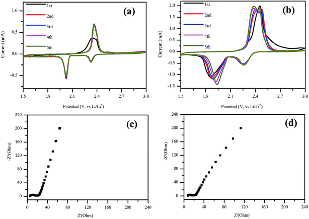
The electrochemical performance of the NSG based cathodes was also evaluated using CV after cycling at 1C rate for 200 cycles (Fig. 6a) and after rate test from 0.1C to 2C (Fig. 6b) respectively. As shown in Fig. 7a, it displays two reduction peaks in the cathodic scan, which was related to the open ring reduction of sulfur (S8) to the soluble lithium polysulfides (Li2Sx, 4 ≤ x ≤ 8), and the reduction of higher order lithium polysulfides to Li2S2 and Li2S.46,47 In the following potential sweeps, the anodic and cathodic curves overlapped, implying high reversibility of the electrode, which was consistent with the results at 0.5C as shown in Fig. S1a.† When the current density increased to 2C, the peak currents of oxidation and reduction increased with the increasing number of potential sweeps (Fig. S1b†). After the rate test, the potential difference decreased with the increasing potential sweeps (Fig. 6b), which indicated that the reversibility of electrode was enhanced with increasing potential cycles. Furthermore, there are two oxidation peaks after the first cycle, which may be related to the stepwise oxidation from Li2S/Li2S2, through low and high order polysulfides, to the elemental sulfur.48,49 EIS measurement was conducted for the NSG/S based electrode before and after 200 charge–discharge cycles at 1C (Fig. 6c and d) and 0.5C rate (Fig. S1d†). From the Nyquist plot of EIS measurement, the charge-transfer resistances remained almost the same (9.4 and 8.4 Ω) after cycling at 1C rate and rate cycling, which can be attributed to the stable structure of the NSG/S composite and a high electrical conductivity that can act as an efficient electron pathway at high current density. However, when the cathode was cycled for 200 times at 0.5C rate, the charge-transfer resistance (31.2 Ω) inside the porous electrode and at SEI interface became much larger (Fig. S1d†). The cycle stability of the cells at 1C and 2C with lower charge-transfer resistance was better than that at 0.5C, which was consistent with the electrochemical test. After 200 cycles, the performance of the batteries at 0.5C was worse than that of 1C and 2C, which is in agreement with the high charge-transfer resistance at 0.5C rate.
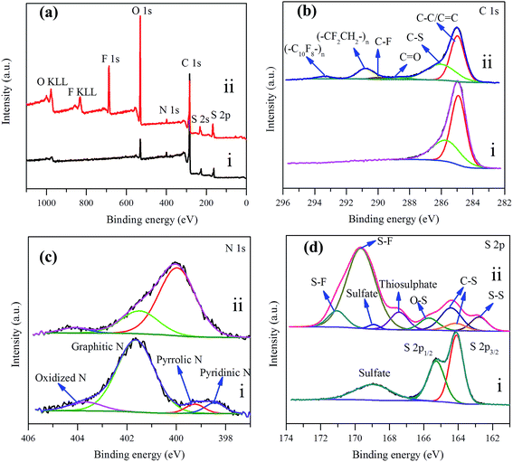 | ||
| Fig. 7 (a) XPS survey spectrum of NSG/S composite (i) before and (ii) after 200 cycles at 1C rate, (b) C 1s, (c) N 1s, and (d) S 2p XPS spectra. | ||
In order to explore the affinitive interaction between heterogeneous dopant and sulfur or polysulfides, XPS analysis was conducted for the NSG/S composite before and after 200 cycles at 1C rate (Fig. 7a–d). In the survey spectrum of the NSG/S composite before cycling (Fig. 7a), the peaks located at 531.10, 399.70, 284.40, 227.50, and 163.00 eV corresponded to O 1s, N 1s, C 1s, S 2s, and S 2p respectively, confirming the presence of C, O, N, and S elements with atomic concentration of 86.33%, 5.99%, 1.78%, and 5.89% respectively. The C 1s spectrum exhibited two peaks at 284.92, and 285.70 eV, which can be ascribed to sp2 hybridized carbon50 (63.45 at%) and C–S bond51 (36.55 at%) (Fig. 7b), implying the presence of strong covalent bonding between the NSG and sulfur. The N 1s spectrum of this composite can be deconvoluted into four peaks (Fig. 7c) at 398.44 eV, 399.25 eV, 401.64 eV, and 403.67 eV originated from pyridinic-like N (6.41 at%), pyrrolic-type N (5.20 at%), graphitic N (79.76 at%), and oxidized N species (8.63 at%), respectively. Pyridinic N is known to influence the structure of graphene platelet and maintains a stable structure in the presence of monovacancy.52 The sp3 bonded pyrrolic N disrupted the planar structure of graphene platelet and dominated in the presence of Stone–Wales defect and divacancy defect.53,54 The S 2p peaks were characterized by a S 2p3/2 and 2p1/2 doublet with an energy separation of 1.18 eV, reconfirming the presence of C–S bonds50 (Fig. 7d). The mismatch of the outermost orbitals of S and C induces a non-uniform spin density distribution on S-doped graphene, which consequently endows graphene platelet preferable for electrocatalytic reactions55 because of the similar electronegativity of S (2.58) and C (2.55).56
After 200 cycles at 1C rate, the survey spectra of NSG/S composite revealed the presence of C, O, N, and S elements, as well as F element (Fig. 7a) originated from the LiTFSI electrolyte and the PVDF binder. The C 1s spectra were dominated by two peaks at 284.98 and 286.05 eV, corresponding to the sp2 hybridized carbon and carbon of C–S nature, accompanied by four weak peaks at 288.69, 290.00, 290.82, and 293.35 eV, which can be ascribed to C![[double bond, length as m-dash]](https://www.rsc.org/images/entities/char_e001.gif) O, C–F, CF2CH2, and C10F8 bonds respectively57–59 (Fig. 7b). Considering that the electrode was rinsed thoroughly with tetrahydrofuran to remove loosely bond LiTFSI electrolyte prior to XPS measurement, the presence of strong F 1s peak (10.06 at%) and C–F component in C 1s peak indicated the passivation of NSG cathode by F containing electrolyte and PVDF binder, suggesting a polymeric surface passivation layer with TFSI anions and the decomposition of electrolyte during battery cycling.60,61
O, C–F, CF2CH2, and C10F8 bonds respectively57–59 (Fig. 7b). Considering that the electrode was rinsed thoroughly with tetrahydrofuran to remove loosely bond LiTFSI electrolyte prior to XPS measurement, the presence of strong F 1s peak (10.06 at%) and C–F component in C 1s peak indicated the passivation of NSG cathode by F containing electrolyte and PVDF binder, suggesting a polymeric surface passivation layer with TFSI anions and the decomposition of electrolyte during battery cycling.60,61
The N 1s XPS spectra of the cathode changed noticeably compared with spectra acquired before cycling (Fig. 7c), which was originated from the N heteroatom and LiNO3 during the charge–discharge process. The peak components at 399.97, 401.49, and 404.13 eV were ascribed to the pyrrolic-like N, graphitic N, and oxidized N respectively, with atomic concentration of 71.48%, 24.34%, and 4.18% respectively.26 Pyridinic and pyrrolic N were formed at the defects sites, and these defects imposed a p-doping effect by withdrawing electrons from the graphene platelet,62 which was beneficial to immobilize polysulfide species to effectively enhance the electrochemical performance of sulfur cathodes.63,64 After 1C rate cycles, the pyridinic-type N became indiscernible and the content of pyrrolic-like N increased, indicating the transformation of pyridinic N to pyrrolic N during the charge–discharge processes which is in agreement with the high electrocatalytic activity of this configuration. In the meantime, the results implied that pyrrolic N was the most favorable N species for the adsorption of polysulfides during the electrochemical process. From the previous research,65 it could be seen that the pyridinic-like N had higher binding energy than the graphitic and oxidized N, implied that pyridinic N significantly enhanced the interaction between the carbon host and the polysulfide guests and thereby effectively prevented the shuttling of polysulfides and improved the electrochemical performance of the batteries, which was consistent with the electrochemical test results. In addition, ameliorative deposition and recharging of Li2S on the region of electron-rich pyridinic N were attributed to the favorable guest–host interaction at the electron-modified interface.66 Pyridinic N-dopants can strongly attract polysulfides with large enough binding energies to effectively anchor soluble polysulfides due to an enhanced attraction between Li ions in polysulfides and pyridinic N-dopants and/or an additional attraction between S anions in polysulfides and Li ions captured by pyridinic N-dopants.67 To investigate the affinitive interaction between pyrrolic N site and lithium polysulfides, ab initio calculation was performed based on density functional theory (DFT). Three soluble polysulfides were used in the simulation (Li2Sx, x = 3, 4, 8), and they formed ring-like configuration with two Li+ ions distributed on each side of the ring after optimization (Fig. 8) in consistent with the literature.68 The overall Mulliken charges of three nitrogen atoms at a pyrrolic nitrogen doped site were −0.358, −0.418, −0.419, much negative than the pyridinic (three nitrogen atoms with −0.249) and graphitic nitrogen (one nitrogen atom with −0.476), indicating that pyrrolic nitrogen doped site imposed the strongest p-doping effect by withdrawing electrons from the graphene platelet. The isosurface of electron density map is also shown in Fig. 8, and the strongly negative charged pyrrolic N doped sites are believed to promote nucleophilic attraction to anchor Li2Sx (x = 3, 4, 8) by charge attraction with Li+. As the most soluble polysulfide, Li2S8 was used to explore the adsorption strength with the heteroatoms. The interaction between Li2S8 and pyrrolic N doped site was stronger than other configurations, in agreement with the literature.69
 | ||
| Fig. 8 Optimized adsorption structures and electron cloud distribution of (a) Li2S3, (b) Li2S4, and (c) Li2S8 near the pyrrolic function on the graphene platelet. | ||
A vastly different S 2p spectrum was also observed compared with the cathode before cycling (Fig. 7d). The peak at 162.79, 164.14, and 164.42 eV corresponded to the S–S and C–S bonds, which can be assigned to sulfur atoms of C–S and S–S bond,20 the peak at 165.70 eV corresponded to O–S bond arising from the sulfate species formed by reaction with residual oxygen containing species during cycling, the peaks at 167.43 and 168.90 eV can be assigned to the thiosulphate and sulfate, and the peaks at 169.65 and 171.05 eV corresponded to the S–F bond70 where the F element originated from the electrolyte, indicating strong covalent interaction between F containing electrolyte and polysulfides on the NSG electrode. The results implied that some of the active S species had been transformed to thiosulphate during cycling.71 The thiosulphate can serve as a highly efficient polysulfide mediator to hinder the loss of lithium polysulfides from the cathode.72 In summary, from the XPS spectra analysis, it can be seen that pyridinic-type N, pyrrolic-like N, and thiosulphate, originating from the amine and thiol groups in L-cysteine, are the dominant factors contributing to the superior electrochemical performance of the NSG/S cathode (Fig. 1e).
Conclusions
In summary, we have developed a novel route to synthesize graphene platelet by in situ nitrogen and sulfur doping using L-cysteine as carbon precursor. The synthesis process utilized NaCl salt as a template and structure directing agent that is non-toxic, easily manageable and can be processed at mild conditions. The prepared hybrid material possesses homogeneous and abundant active sites of heteroatoms via in situ doping, and a thin, flexible and highly conductive mesoporous structure was used as a sulfur host that facilitated the electron transfer and provided easily accessible pores for lithium ions. This unique structure promoted the confinement of lithium polysulfides on the cathode surface and enhanced the discharge capacity of the NSG/S composite in Li–S batteries especially at high rate. This NSG/S composite material exhibited a highly reversible discharge capacity (initial discharge capacity of around 1635 mA h g−1 at 1C) and outstanding performance at high current density (684 mA h g−1 after 200 cycles at 2C). The novel template synthesis method, in situ doping by special precursor using water soluble crystals in this study and the understanding of the electrode surface chemistry during charging and discharging will inspire the design of novel electrode materials for high performance Li–S batteries.Acknowledgements
The authors would like acknowledge the financial supports from National Program on Key Basic Research of China (973 Program, 2015CB258400), the National Thousand Young Talents Program, Natural Science Foundation of China (51508213, 51608217, 21607046), Key project of Hubei Provincial Natural Science Foundation (2014CFA109), General program of Natural Science Foundation of Hubei Province (ZRMS2016000433), Innovative and Interdisciplinary Team at HUST (0118261077) and Independent Innovation Foundation of HUST-Exploration Fund (2016YXMS288, 2014TS092). The authors would like to thank the Analytical and Testing Center of Huazhong University of Science and Technology for providing the facilities to fulfill the experimental measurements, especially Mr Jinjin Wu's assistant with SEM measurement.Notes and references
- S. W. Kim, D. H. Seo, X. Ma, G. Ceder and K. Kang, Adv. Eng. Mater., 2012, 2, 710–721 CAS.
- R. Younesi, G. M. Veith, P. Johansson, K. Edström and T. Vegge, Energy Environ. Sci., 2015, 8, 1905–1922 CAS.
- V. Etacheri, R. Marom, R. Elazari, G. Salitra and D. Aurbach, Energy Environ. Sci., 2011, 4, 3243 CAS.
- L. Ma, K. E. Hendrickson, S. Wei and L. A. Archer, Nano Today, 2015, 10, 315–338 CrossRef CAS.
- J. G. Wang, K. Xie and B. Wei, Nano Energy, 2015, 15, 413–444 CrossRef CAS.
- G. Li, H. Jing, H. Li, L. Liu, Y. Wang, C. Yuan, H. Jiang and L. Chen, Ionics, 2015, 21, 2161–2170 CrossRef CAS.
- J. Ma, Z. Fang, Y. Yan, Z. Yang, L. Gu, Y.-S. Hu, H. Li, Z. Wang and X. Huang, Adv. Eng. Mater., 2015, 5, 1500046 Search PubMed.
- N. Jayaprakash, J. Shen, S. S. Moganty, A. Corona and L. A. Archer, Angew. Chem., Int. Ed., 2011, 50, 5904–5908 CrossRef CAS PubMed.
- Y. Yang, G. Zheng and Y. Cui, Chem. Soc. Rev., 2013, 42, 3018–3032 RSC.
- Z. Li, Y. Huang, L. Yuan, Z. Hao and Y. Huang, Carbon, 2015, 92, 41–63 CrossRef CAS.
- L. Sun, D. Wang, Y. Luo, K. Wang, W. Kong, Y. Wu, L. Zhang, K. Jiang, Q. Li, Y. Zhang, J. Wang and S. Fan, ACS Nano, 2016, 10, 1300–1308 CrossRef CAS PubMed.
- S. Dorfler, M. Hagen, H. Althues, J. Tubke, S. Kaskel and M. J. Hoffmann, Chem. Commun., 2012, 48, 4097–4099 RSC.
- V. A. Agubra, L. Zuniga, D. Flores, J. Villareal and M. Alcoutlabi, Electrochim. Acta, 2016, 192, 529–550 CrossRef CAS.
- Z. Li, S. Zhang, C. Zhang, K. Ueno, T. Yasuda, R. Tatara, K. Dokko and M. Watanabe, Nanoscale, 2015, 7, 14385–14392 RSC.
- W. Choi, I. Lahiri, R. Seelaboyina and Y. S. Kang, Crit. Rev. Solid State Mater. Sci., 2010, 35, 52–71 CrossRef CAS.
- R. J. Young, I. A. Kinloch, L. Gong and K. S. Novoselov, Compos. Sci. Technol., 2012, 72, 1459–1476 CrossRef CAS.
- V. Chabot, D. Higgins, A. Yu, X. Xiao, Z. Chen and J. Zhang, Energy Environ. Sci., 2014, 7, 1564 CAS.
- J. L. Shi, C. Tang, H. J. Peng, L. Zhu, X. B. Cheng, J. Q. Huang, W. Zhu and Q. Zhang, Small, 2015, 11, 5243–5252 CrossRef CAS PubMed.
- L. Zhang, H. Huang, H. Yin, Y. Xia, J. Luo, C. Liang, Y. Gan, X. Tao and W. Zhang, J. Mater. Chem. A, 2015, 3, 16513–16519 CAS.
- S. Yuan, Z. Guo, L. Wang, S. Hu, Y. Wang and Y. Xia, Adv. Sci., 2015, 2, 1500071 CrossRef PubMed.
- S. Niu, W. Lv, C. Zhang, Y. Shi, J. Zhao, B. Li, Q.-H. Yang and F. Kang, J. Power Sources, 2015, 295, 182–189 CrossRef CAS.
- S. Liu, K. Xie, Z. Chen, Y. Li, X. Hong, J. Xu, L. Zhou, J. Yuan and C. Zheng, J. Mater. Chem. A, 2015, 3, 11395–11402 CAS.
- M. Guo, J. Huang, X. Kong, H. Peng, H. Shui, F. Qian, L. Zhu, W. Zhu and Q. Zhang, New Carbon Mater., 2016, 31, 352–362 CrossRef.
- J. Song, M. L. Gordin, T. Xu, S. Chen, Z. Yu, H. Sohn, J. Lu, Y. Ren, Y. Duan and D. Wang, Angew. Chem., Int. Ed., 2015, 54, 4325–4329 CrossRef CAS PubMed.
- S. Zhang, Inorg. Chem. Front., 2015, 2, 1059–1069 RSC.
- J. Zhang, Y. Cai, Q. Zhong, D. Lai and J. Yao, Nanoscale, 2015, 7, 17791–17797 RSC.
- Y. Xie, Z. Meng, T. Cai and W. Q. Han, ACS Appl. Mater. Interfaces, 2015, 7, 25202–25210 CAS.
- F. Wu, J. Li, Y. Tian, Y. Su, J. Wang, W. Yang, N. Li, S. Chen and L. Bao, Sci. Rep., 2015, 5, 13340 CrossRef CAS PubMed.
- S. Niu, W. Lv, G. Zhou, Y. He, B. Li, Q. H. Yang and F. Kang, Chem. Commun., 2015, 51, 17720–17723 RSC.
- Y. Cao, X. L. Li, M. S. Zheng, M. P. Yang, X. L. Yang and Q. F. Dong, Electrochim. Acta, 2016, 192, 467–474 CrossRef CAS.
- L. Chen, Z. Chen, Z. Huang, Y. Wang, H. Zhou and Y. Kuang, New J. Chem., 2015, 39, 8901–8907 RSC.
- G. Qu, J. Cheng, X. Li, L. Huang, W. Ni, Z. Wang and B. Wang, ACS Appl. Mater. Interfaces, 2015, 7, 16668–16675 CAS.
- G. Hu, C. Xu, Z. Sun, S. Wang, H. M. Cheng, F. Li and W. Ren, Adv. Mater., 2016, 28, 1603–1609 CrossRef CAS PubMed.
- L. Fei, X. Li, W. Bi, Z. Zhuo, W. Wei, L. Sun, W. Lu, X. Wu, K. Xie, C. Wu, H. L. Chan and Y. Wang, Adv. Mater., 2015, 27, 5936–5942 CrossRef CAS PubMed.
- Z. Zhang, G. Wang, Y. Lai, J. Li, Z. Zhang and W. Chen, J. Power Sources, 2015, 300, 157–163 CrossRef CAS.
- J. Xiao, H. Wang, X. Li, Z. Wang, J. Ma and H. Zhao, J. Mater. Sci.: Mater. Electron., 2015, 26, 7895–7900 CrossRef CAS.
- Z. Li and L. Yin, Nanoscale, 2015, 7, 9597–9606 RSC.
- R. Ansari, S. Sahmani and B. Arash, Phys. Lett. A, 2010, 375, 53–62 CrossRef CAS.
- F. Tuinstra, J. Chem. Phys., 1970, 53, 1126 CrossRef CAS.
- T. Bordjiba, M. Mohamedi and L. H. Dao, J. Power Sources, 2007, 172, 991–998 CrossRef CAS.
- Z. Zhang, Z. Li, F. Hao, X. Wang, Q. Li, Y. Qi, R. Fan and L. Yin, Adv. Funct. Mater., 2014, 24, 2500–2509 CrossRef CAS.
- H. Xu, L. Qie and A. Manthiram, Nano Energy, 2016, 26, 224–232 CrossRef CAS.
- L. Zhang, X. Zhao, M. D. Stoller, Y. Zhu, H. Ji, S. Murali, Y. Wu, S. Perales, B. Clevenger and R. S. Ruoff, Nano Lett., 2012, 12, 1806–1812 CrossRef CAS PubMed.
- Z. Gao, J. Wang, Z. Li, W. Yang, B. Wang, M. Hou, Y. He, Q. Liu, T. Mann, P. Yang, M. Zhang and L. Liu, Chem. Mater., 2011, 23, 3509–3516 CrossRef CAS.
- L. H. Hu, F. Y. Wu, C. T. Lin, A. N. Khlobystov and L. J. Li, Nat. Commun., 2013, 4, 1687 CrossRef PubMed.
- G. Zhou, L. Li, D. W. Wang, X. Y. Shan, S. Pei, F. Li and H. M. Cheng, Adv. Mater., 2015, 27, 641–647 CrossRef CAS PubMed.
- J. Wang, Y. S. He and J. Yang, Adv. Mater., 2015, 27, 569–575 CrossRef CAS PubMed.
- J. Conder, A. Forner-Cuenca, E. M. Gubler, L. Gubler, P. Novak and S. Trabesinger, ACS Appl. Mater. Interfaces, 2016, 8, 18822–18831 CAS.
- X. Zhou, J. Xie, J. Yang, Y. Zou, J. Tang, S. Wang, L. Ma and Q. Liao, J. Power Sources, 2013, 243, 993–1000 CrossRef CAS.
- G. Li, J. Sun, W. Hou, S. Jiang, Y. Huang and J. Geng, Nat. Commun., 2016, 7, 10601 CrossRef CAS PubMed.
- Z. Wang, Y. Dong, H. Li, Z. Zhao, H. B. Wu, C. Hao, S. Liu, J. Qiu and X. W. Lou, Nat. Commun., 2014, 5, 5002 CrossRef CAS PubMed.
- X. Wang, G. Sun, P. Routh, D. H. Kim, W. Huang and P. Chen, Chem. Soc. Rev., 2014, 43, 7067 RSC.
- Z. Hou, X. Wang, T. Ikeda, K. Terakura, M. Oshima and M.-a. Kakimoto, Phys. Rev. B: Condens. Matter Mater. Phys., 2013, 87, 165401 CrossRef.
- T. Schiros, D. Nordlund, L. Palova, D. Prezzi, L. Zhao, K. S. Kim, U. Wurstbauer, C. Gutierrez, D. Delongchamp, C. Jaye, D. Fischer, H. Ogasawara, L. G. Pettersson, D. R. Reichman, P. Kim, M. S. Hybertsen and A. N. Pasupathy, Nano Lett., 2012, 12, 4025 CrossRef CAS PubMed.
- J. Liang, Y. Jiao, M. Jaroniec and S. Z. Qiao, Angew. Chem., Int. Ed., 2012, 51, 11496 CrossRef CAS PubMed.
- S. Glenis, A. J. Nelson and M. M. Labes, J. Appl. Phys., 1999, 86, 4464 CrossRef CAS.
- M. Ackeret, Surf. Sci. Spectra, 1992, 1, 108 CrossRef CAS.
- S. C. Yoon and B. D. Ratner, Macromolecules, 1986, 19, 1068–1079 CrossRef CAS.
- H. S. Munro and C. Till, J. Polym. Sci., Part A: Polym. Chem., 1987, 25, 1065–1071 CrossRef CAS.
- S. A. Delp, O. Borodin, M. Olguin, C. G. Eisner, J. L. Allen and T. R. Jow, Electrochim. Acta, 2016, 209, 498–510 CrossRef CAS.
- D. Ensling, M. Stjerndahl, A. Nytén, T. Gustafsson and J. O. Thomas, J. Mater. Chem., 2009, 19, 82–88 RSC.
- Z. Wang, Y. Dong, H. Li, Z. Zhao, H. B. Wu, C. Hao, S. Liu, J. Qiu and X. W. Lou, Nat. Commun., 2014, 5, 5002 CrossRef CAS PubMed.
- K. Han, J. Shen, S. Hao, H. Ye, C. Wolverton, M. C. Kung and H. H. Kung, ChemSusChem, 2014, 7, 2545–2553 CrossRef CAS PubMed.
- M. Yu, R. Li, Y. Tong, Y. Li, C. Li, J. D. Hong and G. Q. Shi, J. Mater. Chem. A, 2015, 3, 9609–9615 CAS.
- T. Z. Hou, X. Chen, H. J. Peng, J. Q. Huang, B. Q. Li, Q. Zhang and B. Li, Small, 2016, 12, 3283–3291 CrossRef CAS PubMed.
- H. J. Peng, T. Z. Hou, Q. Zhang, J. Q. Huang, X. B. Cheng, M. Q. Guo, Z. Yuan, L. Y. He and F. Wei, Adv. Mater. Interfaces, 2014, 1, 1400227 CrossRef.
- L. C. Yin, J. Liang, G. M. Zhou, F. Li, R. Saito and H. M. Cheng, Nano Energy, 2016, 25, 203–210 CrossRef.
- Z. Ji, B. Han, Q. Li, C. Zhou, Q. Gao, K. Xia and J. Wu, J. Phys. Chem. C, 2015, 119, 20495–20502 CAS.
- J. Balach, H. K. Singh, S. Gomoll, T. Jaumann, M. Klose, S. Oswald, M. Richter, J. Eckert and L. Giebeler, ACS Appl. Mater. Interfaces, 2016, 8, 14586–14595 CAS.
- B. J. Lindberg, K. Hamrin, G. Johansson, U. Gelius, A. Fahlman, C. Nordling and K. Siegbahn, Phys. Scr., 1970, 1, 286 CrossRef CAS.
- X. Feng, M. K. Song, W. C. Stolte, D. Gardenghi, D. Zhang, X. Sun, J. Zhu, E. J. Cairns and J. Guo, Phys. Chem. Chem. Phys., 2014, 16, 16931–16940 RSC.
- X. Liang, C. Hart, Q. Pang, A. Garsuch, T. Weiss and L. F. Nazar, Nat. Commun., 2015, 6, 5682 CrossRef PubMed.
Footnote |
| † Electronic supplementary information (ESI) available. See DOI: 10.1039/c7ra01946g |
| This journal is © The Royal Society of Chemistry 2017 |

