 Open Access Article
Creative Commons Attribution 3.0 Unported Licence
Efficient small molecule photovoltaic donor based on 2,3-diphenyl-substituted quinoxaline core for solution-processed organic solar cells†
Bao Xie‡
a,
Sheng Bi‡b,
Rui Wu‡a,
Lunxiang Yina,
Changyan Jiac,
Zhengjiang Caia and
Yanqin Li *a
*a
aSchool of Chemistry, Dalian University of Technology, Linggong Road 2, Dalian, P. R. China. E-mail: liyanqin@dlut.edu.cn; Fax: +86-411-84986040; Tel: +86-411-84986040
bSchool of Mechanical Engineering, Dalian University of Technology, Linggong Road 2, Dalian, P. R. China
cHunan Provincial Key Laboratory of Fine Ceramics and Powder Materials, Hunan University of Humanities, Science and Technology, Lou'di, Hunan 417000, P. R. China
First published on 3rd May 2017
Abstract
A novel D–π–A–π–D-type organic small molecule (OSM) named (TPACN)2Qx was designed and synthesized for solution-processible organic solar cells (OSCs), which contained 2,3-diphenyl-substituted quinoxaline (Qx) as the central acceptor (A) unit, triphenylamine (TPA) as terminal electron-donor (D) moieties, and acrylonitrile as the π-linkage segment. With an effective electron-withdrawing property and relatively stable quinoid geometry of Qx, (TPACN)2Qx exhibits a narrow band-gap of 1.88 eV and strong and broad absorption at 300–700 nm. As a consequence, an excellent power conversion efficiency (PCE) of 6.25% was achieved based on the (TPACN)2Qx:PC61BM blend using a simple spin-coating process in a solution, which is the highest efficiency achieved to date for Qx-core based solution-processed OSM photovoltaic (PV) devices. The impressive result demonstrates that OSMs employing quinoxaline derivative as an electrophilic unit can compete with their polymer counterparts.
Introduction
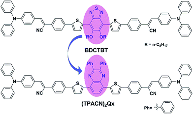
OSCs have emerged as a competitive alternative to inorganic solar cells for their prominent advantages of light weight, low cost and flexibility in large-scale fabrication.1 Over the past two decades, solution-processed bulk heterojunction (BHJ) photovoltaic (PV) devices based on a blend of electron donors and acceptors have attracted much attention and extensive investigation due to their higher internal quantum efficiency and the easier fabrication technology.2 Nowadays, most research efforts have been focused on donor materials because fullerene derivatives, such as [6,6]-phenyl-C61-butyric acid methyl ester (PC61BM) and [6,6]-phenyl-C71-butyric acid methyl ester (PC71BM), have proven to be ideal acceptor materials and have already been commercialized.3 Among the OSC donor materials, OSM materials have shown numerous promising advantages over conjugated polymers in terms of well-defined structure, easier purification, better batch-to-batch reproducibility and high charge carrier mobility.4 In particular, an encouraging PCE of 11.30% has been achieved based on OSM donor materials,5 which is comparable to the PV performance of the best polymers.6 However, the overall performance of OSMs, to date, is still behind those of their polymer counterparts. Therefore, BHJ OSCs based on OSMs still require intensive investigation for the design of materials.To design ideal OSM donor materials, the following issues should be considered:7 (I) possessing broad and strong absorption via reducing the band-gap (Eg) of molecules, which results in an increased short-circuit current density (Jsc); (II) lowering the highest occupied molecular orbit (HOMO) of materials, which correlates with the improved open-circuit voltage (Voc); (III) possessing better solubility, miscibility and film-forming characteristics to improve the morphology of the active layer and increase the fill factor (FF) of the PV device. To address these issues, developing new D–A conjugated molecules has become an effective strategy as the Eg and energy levels of D–A-type OSMs can be effectively tuned through chemical structure modifications.8 In our previous study, we found that OSMs with alternating D–A conjugated configuration could possess both lower HOMO level and narrow band-gap by tuning their building blocks.9 We have reported a D–π–A–π–D-type OSM donor material, BDCTBT,10 in which benzothiadiazole (BT) as the A unit and TPA as the D unit were connected by a π-bridge containing an acrylonitrile segment, and the chemical structure of BDCTBT is shown in Fig. 1. In practical photovoltaic testing, the devices based on BDCTBT as donor and PC61BM as acceptor exhibited a PCE of 3.85%,10 and after subsequent device optimization, a relatively high PCE of 4.84% was obtained.9b Our research demonstrates that D–A–D-type molecules with a π-bridge containing an acrylonitrile segment are a successful configuration for OSM donor material. To date, we have found that the PCEs of solution-processed BHJ devices based on D–A–D-type OSM with BT as the electrophilic core have never exceeded 5%.8c,9b,11 Based on above design concepts, we synthesized a new D–A–D-type OSM named (TPACN)2Qx as shown in Fig. 1, in which the central A unit of BDCTBT was replaced by a strong electron-withdrawing unit, which was 2,3-diphenyl-substituted quinoxaline (Qx).
Quinoxaline, as one significant class of high performance pigments, is widely considered as a promising building block for OSCs due to the strong electron-withdrawing property of two imine nitrogens and relatively stable quinoid geometry.12 Quinoxaline derivatives can be easily structurally modified, and their electronic properties can be changed with various substituents. Among a wide variety of quinoxaline derivatives, Qx has shown to be an easily synthesized excellent electron-withdrawing unit for the synthesis of narrow band gap conjugated polymers used in high efficiency polymer solar cells (PSCs).13 Thus far, PSCs based on Qx have achieved promising PCEs over 8% with careful device optimization.14 In addition, important progress has also been made on Qx-based dye sensitized solar cells (DSSCs) with a PCE near 10%.15 Although Qx shows outstanding PV performance in PSCs and DSSCs, it seems to be hysteretic in OSM solar cells.16 Consequently, we believe that Qx-based OSMs possess tremendous development potential for BHJ-OSCs.
Accordingly, (TPACN)2Qx was designed and synthesized successfully, and its photoelectric properties were fully investigated. Remarkably, an excellent PCE of 6.25% has been achieved for BHJ devices based on (TPACN)2Qx as the donor and PC61BM as the acceptor, which is the highest efficiency reported to date for solution processed Qx-based OSM BHJ-OSCs. This study clearly indicates that Qx-based OSMs possess great potential in obtaining high performance for solution-processed PV devices.
Experimental
Reagents and materials
All reagents were purchased commercially and used without further purification unless specified. All reactions were carried out with the standard Schlenk technique unless otherwise indicated. Toluene and tetrahydrofuran (THF) were pretreated over sodium/benzophenone under nitrogen atmosphere before reaction.Photovoltaic device fabrication
The BHJ device was fabricated via solution-processable spin-coating process with a typical architecture of ITO/PEDOT:PSS/donor:PC61BM/Al. The ITO-glass substrates were cleaned in an ultrasonic bath in deionized water, methanol, acetone, toluene and isopropanol for 5 min, successively. After being dried with high pressure nitrogen gas-flow, a thin layer of poly(3,4-ethylenedioxythiophene):poly(styrene sulfonate) (PEDOT![[thin space (1/6-em)]](https://www.rsc.org/images/entities/char_2009.gif) :
:![[thin space (1/6-em)]](https://www.rsc.org/images/entities/char_2009.gif) PSS) was spin-coated onto the pretreated substrate at 4000 rpm s−1 for 60 s. After being baked at 120 °C for 15 min, all prepared substrates were transferred into the nitrogen-filled glovebox. Then, the blended solution of (TPACN)2Qx and PC61BM in chloroform with various weight ratios was spin-coated on the top of the prepared substrate at 1500 rpm s−1 for 60 s. Finally, an aluminium layer as the electrode was deposited on top of the active layer by thermal evaporation under vacuum (ca. 10−4 Pa), yielding six individual cells with 5 mm2 effective area for each. The hole-only devices using high work-function metal gold (Au) as the electrode for hole mobility measurement were fabricated with a structure of ITO/PEDOT:PSS/donor:PC61BM/Au.
PSS) was spin-coated onto the pretreated substrate at 4000 rpm s−1 for 60 s. After being baked at 120 °C for 15 min, all prepared substrates were transferred into the nitrogen-filled glovebox. Then, the blended solution of (TPACN)2Qx and PC61BM in chloroform with various weight ratios was spin-coated on the top of the prepared substrate at 1500 rpm s−1 for 60 s. Finally, an aluminium layer as the electrode was deposited on top of the active layer by thermal evaporation under vacuum (ca. 10−4 Pa), yielding six individual cells with 5 mm2 effective area for each. The hole-only devices using high work-function metal gold (Au) as the electrode for hole mobility measurement were fabricated with a structure of ITO/PEDOT:PSS/donor:PC61BM/Au.
Measurements and characterization
1H-NMR and 13C-NMR spectra were recorded by Bruker AVANCE II 400 MHz spectrometer with CDCl3 as solvent and tetramethylsilane (TMS) as internal standard substance. High resolution mass spectra (HRMS) were recorded with a MALDI Micro MX spectrometer. The UV-Vis absorption spectra of the material in chloroform solution and in the film state were taken on an Agilent Cary 5000 spectrophotometer. Cyclic voltammetry (CV) experiments were conducted using a CHI610D electrochemical workstation from CH Instruments, Inc., and it was performed in 0.1 M anhydrous Bu4NBF4/CH2Cl2 solution at a scan rate of 100 mV s−1 under nitrogen atmosphere, using the glass-carbon electrode, Ag/Ag+ electrode (Ag in 0.1 M AgNO3 solution of MeCN) and platinum wire electrode as the working electrode, reference electrode and counter electrode, respectively. In addition, the ferrocene–ferrocenium (Fc/Fc+) couple was selected as the internal standard. Electrochemical band gaps (ECVg) and the pertinent energy levels (HOMOCV and LUMOCV) could be achieved according to the following empirical equations:17 HOMOCV/LUMOCV = −[Eox/red − Eferrocene1/2 + 4.8] eV and ECVg = LUMOCV − HOMOCV, where Eox was the measured onset oxidation potential and Ered was the measured onset reduction potential relative to Ag/Ag+, and Eferrocene1/2 = 0.05 eV versus Ag/Ag+. Thermogravimetric analysis (TGA) was carried out on a TA Instruments Q50 thermogravimetric analyzer at a heating rate of 10 °C min−1 under nitrogen atmosphere. Differential scanning calorimetry (DSC) was performed under nitrogen atmosphere at a heating/cooling rate of 10 °C min−1 with a TA Instruments Q20 differential scanning calorimeter. Atomic force microscopy (AFM) measurement was conducted with a DI Nanoscope Dimension 3100 atomic force microscope. The current density–voltage (J–V) characteristics of PV devices were measured with a computer-controlled Keithley 2400 Source Measure Unit under simulated AM 1.5 G illumination with an intensity of 100 mW cm−2, calibrated with a standard silicon solar cell. The incident-photons-to-current efficiency (IPCE) measurement was recorded on a SM-25 photoelectric conversion analyzer. The hole-mobility (μh) measurement of the material was performed with the Keithley 2400 Source Measure Unit system in dark. The μh data can be received by fitting the J–V curves in a double logarithmic scale with a space-charge-limited current (SCLC) model according to the Mott–Gurney law:18 J = (9/8) ε0 εr μh(V2/L3), where J is current density, ε0 is the permittivity of free space, εr is the relative permittivity and assumed as approximately 3.0, μh is the hole mobility value, V is the effective voltage, and L is the thickness of the active layer.Synthetic procedures
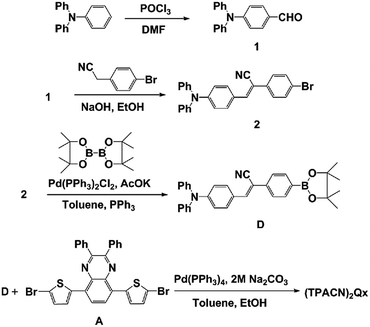
The synthetic process of (TPACN)2Qx is described in Scheme 1.The quinoxaline-based acceptor (compound A) was synthesized in six steps starting from commercially available 1,2-benzenediamine following the procedures reported in literature.10,12b,19 Starting from the commercialized triphenylamine as original material, a solution of POCl3 and N,N-dimethylformamide (DMF) was dropped carefully via Vilsmeier reaction to obtain compound 1. Knoevenagel condensation reaction of 4-bromophenyl acetonitrile and 4-(diphenylamino)benzaldehyde was carried out using NaOH as a base in EtOH, resulting in compound 2 in a yield of 91%. The donor unit (compound D) was synthesized by Miyauraborylation of compound 2 and bis(pinacolato)diborane in a yield of 81%. Finally, (TPACN)2Qx was prepared by Pd(PPh3)4-assisted Suzuki coupling reaction of compound D and compound A in a yield of 90%. Detailed synthetic procedures and characterization are given in ESI.† Mp: 290–293 °C. 1H-NMR (400 MHz, CDCl3): δ 8.10 (s, 2H), 7.78 (d, J = 8.0 Hz, 10H), 7.66 (m, 8H), 7.48–7.39 (m, 10H), 7.32 (t, J = 8.0 Hz, 8H), 7.17–7.11 (m, 12H), 7.07 (d, J = 8.0 Hz, 4H). 13C-NMR (100 MHz, CDCl3): δ 151.67, 149.99, 146.66, 146.63, 146.06, 140.90, 138.60, 137.14, 134.89, 133.84, 130.95, 130.73, 130.61, 129.60, 129.25, 128.27, 127.48, 126.47, 126.37, 126.08, 125.89, 125.77, 124.43, 123.33, 120.86, 118.69, 107.19. MALDI-TOF HRMS: 1187.3934 [M+] (calcd for C82H55N6S2: 1187.3930).
Results and discussion
Material characterization and thermal properties
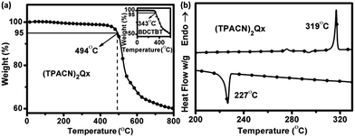
The chemical structure of the newly synthesized compound (TPACN)2Qx was confirmed by 1H-NMR, 13C-NMR spectroscopy and MALDI-TOF HRMS, as shown in the Experimental section. These results are consistent with the proposed structure and molecular weight. Furthermore, (TPACN)2Qx possesses excellent solubility in common organic solvents such as chloroform, dichlorobenzene, and toluene, which meets the requirement for solution-processable PV device fabrication.The thermal stability properties of the material were investigated first by means of thermogravimetric analysis (TGA). The 5% weight loss temperature (Td) of (TPACN)2Qx was determined from TGA curves, as shown in Fig. 2(a). It exhibits particularly high thermal stability with a Td greater than 494 °C, which is 151 °C higher than Td of the reference compound BDCTBT as plotted in the inset of Fig. 2(a). In addition, the thermal properties of (TPACN)2Qx were investigated by differential scanning calorimetry (DSC) analysis. Fig. 2(b) shows the DSC curves of (TPACN)2Qx at a heating/cooling rate of 10 °C min−1 under a nitrogen flow. When (TPACN)2Qx was heated, the endothermic peak due to the melting temperature was observed at 319 °C. Cooling process exhibited an opposite exothermic peak due to crystallization at ca. 227 °C, and the corresponding enthalpy was 78.8 kJ mol−1. The larger crystallization enthalpy indicates that it has a tendency to crystallize to keep its stability. In should be noted that the crystallization of the materials in the active layer is beneficial to charge separation and transport in PV applications.20
Theoretical calculations
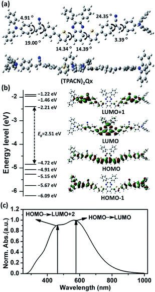
The computational analysis can be used to screen a variety of OSMs and highlight some promising chemical structures to pursue synthetically, which is also desirable for investigation of the theoretical optical and electronic properties of new materials.21 In this study, we preliminarily predict the molecular geometry and investigate the theoretical optical and electronic properties of (TPACN)2Qx with density functional theory (DFT) and time dependent-density functional theory (TD-DFT) using Gaussian 09 software with the Becke's three-parameter gradient-corrected functional (B3LYP) with a polarized 6-31G(d) basis set.22 The summary of the computational results is represented in Fig. 3, with the calculated data of electronic transitions included in the ESI†. The optimized geometry of (TPACN)2Qx and calculated dihedral angles are shown in Fig. 3(a). According to the optimized molecular geometry, the torsion angles between the Qx and thiophene units are ca. 14°, resulting in the molecular backbone being slightly distorted from planarity, and this distortion is a result of steric demand of the molecular structure. As expected, the torsion angles between the acrylonitrile linker and terminal TPA unit are only ca. 4°, which depict a considerably coplanar structure. As we know, the coplanar properties of the molecular backbone could probably have a pronounced influence on the optical and electronic properties of materials. Herein, a theoretically effective intramolecular charge transfer (ICT) process between terminal TPA and central Qx via the π-linker could be predicted.The computational energy levels and molecular orbital depictions are plotted in Fig. 3(b), with detailed electronic transition data included in Table S1 of ESI†. The electronic densities of the HOMO are highly distributed on the entire molecular backbone without a significantly biased distribution, whereas those of lowest unoccupied molecular orbital (LUMO) are predominantly localized at the central electrophilic core (Qx), revealing an apparent ICT process from the electron-donating segment to the electron-withdrawing unit. Furthermore, the electronic densities of HOMO-1 are predominantly located on their terminal segments with a greater proportion. This feature reveals that the terminal TPA group could probably play an important role in stabilizing the separated hole and thus improve the hole transporting capacity.23 The calculated energy levels of the HOMODFT and LUMODFT are −4.72 eV and −2.21 eV, respectively. Despite the error between theory and experimental results, the computational analysis has proven to be desirable for early design of new materials.24
The theoretical optical absorption spectrum of (TPACN)2Qx with the related electronic transitions is shown in Fig. 3(c). Accordingly, two primary absorption bands were observed. The long wavelength absorption band resulted from the first singlet excited state, which could be attributed to the electron transition from HOMO to LUMO. The short one primarily resulted from the sixth singlet excited state, which is a result of the electron transition from HOMO to LUMO+2. Despite the discrepancy between simulation and experiment caused by solvent effects and intermolecular interactions and so on, the computational results could provide important reference for the experimental data.
Optical properties
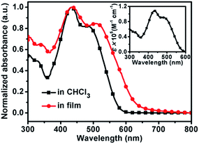
The optical properties of (TPACN)2Qx were studied using UV-Vis absorption measurement. The absorption profiles in chloroform solution and in the film state are shown in Fig. 4 with the corresponding optical data summarized in Table 1. This compound exhibits two primary absorption peaks in a broad absorption range covering 300–600 nm in solution and 300–700 nm in film. Moreover, the quantitative measurement of absorption in solution (inset of Fig. 4) shows that this compound possesses strong absorption capacity with a high molar extinction coefficient (ε) of 1.08 × 10⁵ and 9.08 × 10⁴ M−1 cm−1 at 433 and 482 nm, respectively. In comparison with the ICT-induced maximum absorption peak in the long wavelength (λsol) of (TPACN)2Qx, the spectrum in the film state is greatly broadened, and the ICT-induced absorption peak (λfilm) is red-shifted 25 nm, indicating a strong intermolecular π–π interaction in the solid state. Accordingly, the optical band gap (Eoptg) of (TPACN)2Qx estimated with its absorption onset is 1.94 eV, which is smaller than Eoptg of the reference compound BDCTBT as listed in Table 1. This result is in accordance with its experimental band gap via the electrochemical method. Therefore, (TPACN)2Qx obtained a smaller value of Eoptg compared to that of BDCTBT, which could probably contribute to an efficient short-circuit current.Electrochemical properties
To investigate the electrochemical property of (TPACN)2Qx, cyclic voltammetry (CV) measurement was carried out in 0.1 M Bu4NBF4/CH2Cl2 solution under the protection of nitrogen (the experimental details are described in the Experimental section). The cyclic voltammogram of (TPACN)2Qx and corresponding electrochemical energy-level diagram are depicted in Fig. 5, with the pertinent data summarized in Table 1. The onset oxidation potential (Eox) at 0.4 V is clearly observed in the anode potential region as a result of the oxidation of the TPA unit. On the other hand, the onset reduction potentials (Ered) at −1.48 V are easily obtained in the cathodic potential region due to the reduction of Qx as the electron-withdrawing core. The electrochemical energy levels (HOMOCV and LUMOCV) and band gap (ECVg) could be calculated from Eox and Ered (the calculation methods are recorded in the Experimental section). Accordingly, the HOMOCV of (TPACN)2Qx is −5.15 eV, and the LUMOCV is −3.27 eV, resulting in a narrow ECVg of 1.88 eV. Therefore, (TPACN)2Qx obtained a smaller value of ECVg relative to that of BDCTBT, which could be rationally ascribed to the strong electron-withdrawing effect of Qx with electrophilic characteristics. This result is in good agreement with the spectral data. Herein, the improvement of Jsc of the PV device will be expected as a result of the decreased energy gap of (TPACN)2Qx relative to that of BDCTBT. The electrochemical energy level of (TPACN)2Qx together with PC61BM was plotted in Fig. 5(b). These results clearly indicate that this compound in principle can behave as a donor in the BHJ PV device with PC61BM as the acceptor material.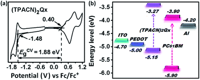 | ||
| Fig. 5 (a) Cyclic voltammogram of (TPACN)2Qx in 0.1 M Bu4NBF4/CH2Cl2 solution at a scan rate of 100 mV s−1; (b) energy-level diagram of the components for (TPACN)2Qx-based photovoltaic device. | ||
Photovoltaic properties
To fully investigate the PV characteristics of (TPACN)2Qx, the BHJ devices with a conventional structure of ITO/PEDOT:PSS/(TPACN)2Qx![[thin space (1/6-em)]](https://www.rsc.org/images/entities/char_2009.gif) :
:![[thin space (1/6-em)]](https://www.rsc.org/images/entities/char_2009.gif) PC61BM/Al were fabricated by a solution-processed spin-coating technique. The optimization of (TPACN)2Qx and PC61BM (D/A) weight ratios was studied in particular; herein, the blend of (TPACN)2Qx and PC61BM with varied weight ratios (1
PC61BM/Al were fabricated by a solution-processed spin-coating technique. The optimization of (TPACN)2Qx and PC61BM (D/A) weight ratios was studied in particular; herein, the blend of (TPACN)2Qx and PC61BM with varied weight ratios (1![[thin space (1/6-em)]](https://www.rsc.org/images/entities/char_2009.gif) :
:![[thin space (1/6-em)]](https://www.rsc.org/images/entities/char_2009.gif) 1, 1
1, 1![[thin space (1/6-em)]](https://www.rsc.org/images/entities/char_2009.gif) :
:![[thin space (1/6-em)]](https://www.rsc.org/images/entities/char_2009.gif) 2 and 1
2 and 1![[thin space (1/6-em)]](https://www.rsc.org/images/entities/char_2009.gif) :
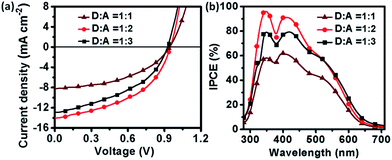
:![[thin space (1/6-em)]](https://www.rsc.org/images/entities/char_2009.gif) 3) was performed. The J–V curves of the devices with varied D/A weight ratios are shown in Fig. 6(a), and the relevant PV parameters are listed in Table 2. The initial device was fabricated from the blend solution of (TPACN)2Qx and PC61BM in a 1
3) was performed. The J–V curves of the devices with varied D/A weight ratios are shown in Fig. 6(a), and the relevant PV parameters are listed in Table 2. The initial device was fabricated from the blend solution of (TPACN)2Qx and PC61BM in a 1![[thin space (1/6-em)]](https://www.rsc.org/images/entities/char_2009.gif) :
:![[thin space (1/6-em)]](https://www.rsc.org/images/entities/char_2009.gif) 1 (w/w) ratio, and it showed a PCE of 3.53% with JSC of 8.23 mA cm−2, VOC of 0.94 V and FF of 0.46. After the D/A composition ratio was increased to 1
1 (w/w) ratio, and it showed a PCE of 3.53% with JSC of 8.23 mA cm−2, VOC of 0.94 V and FF of 0.46. After the D/A composition ratio was increased to 1![[thin space (1/6-em)]](https://www.rsc.org/images/entities/char_2009.gif) :
:![[thin space (1/6-em)]](https://www.rsc.org/images/entities/char_2009.gif) 2 (w/w), the PCE greatly increased to 6.25% with a high JSC of 14.08 mA cm−2, VOC of 0.95 V and FF of 0.47. A 5.09% drop in efficiency was observed on increasing the fullerene loading at the D/A composition ratio of 1
2 (w/w), the PCE greatly increased to 6.25% with a high JSC of 14.08 mA cm−2, VOC of 0.95 V and FF of 0.47. A 5.09% drop in efficiency was observed on increasing the fullerene loading at the D/A composition ratio of 1![[thin space (1/6-em)]](https://www.rsc.org/images/entities/char_2009.gif) :
:![[thin space (1/6-em)]](https://www.rsc.org/images/entities/char_2009.gif) 3 (w/w), with a decreased JSC of 12.86 mA cm−2, VOC of 0.92 V and FF of 0.43. Remarkably, the device based on (TPACN)2Qx
3 (w/w), with a decreased JSC of 12.86 mA cm−2, VOC of 0.92 V and FF of 0.43. Remarkably, the device based on (TPACN)2Qx![[thin space (1/6-em)]](https://www.rsc.org/images/entities/char_2009.gif) :
:![[thin space (1/6-em)]](https://www.rsc.org/images/entities/char_2009.gif) PC61BM composition in a 1
PC61BM composition in a 1![[thin space (1/6-em)]](https://www.rsc.org/images/entities/char_2009.gif) :
:![[thin space (1/6-em)]](https://www.rsc.org/images/entities/char_2009.gif) 2 weight ratio showed the optimal PV performance. This value is the highest efficiency reported so far for a solution-processed OSM PV-device using Qx as the electrophilic core. It should be noted that high efficiency might be closely related to a more optimized morphology of the active layer. The better PV performance of the device with D/A ratio of 1
2 weight ratio showed the optimal PV performance. This value is the highest efficiency reported so far for a solution-processed OSM PV-device using Qx as the electrophilic core. It should be noted that high efficiency might be closely related to a more optimized morphology of the active layer. The better PV performance of the device with D/A ratio of 1![[thin space (1/6-em)]](https://www.rsc.org/images/entities/char_2009.gif) :
:![[thin space (1/6-em)]](https://www.rsc.org/images/entities/char_2009.gif) 2 (w/w) was further supported by atomic force microscopy (AFM) analysis of the blended (TPACN)2Qx
2 (w/w) was further supported by atomic force microscopy (AFM) analysis of the blended (TPACN)2Qx![[thin space (1/6-em)]](https://www.rsc.org/images/entities/char_2009.gif) :
:![[thin space (1/6-em)]](https://www.rsc.org/images/entities/char_2009.gif) PC61BM active layer (Fig. S14 in ESI†). Although all the blend films with various D/A composition ratios (1
PC61BM active layer (Fig. S14 in ESI†). Although all the blend films with various D/A composition ratios (1![[thin space (1/6-em)]](https://www.rsc.org/images/entities/char_2009.gif) :
:![[thin space (1/6-em)]](https://www.rsc.org/images/entities/char_2009.gif) 1, 1
1, 1![[thin space (1/6-em)]](https://www.rsc.org/images/entities/char_2009.gif) :
:![[thin space (1/6-em)]](https://www.rsc.org/images/entities/char_2009.gif) 2, 1
2, 1![[thin space (1/6-em)]](https://www.rsc.org/images/entities/char_2009.gif) :
:![[thin space (1/6-em)]](https://www.rsc.org/images/entities/char_2009.gif) 3, w/w) correspond to the favourable bicontinuous interpenetrating networks, the blend with a D/A ratio of 1
3, w/w) correspond to the favourable bicontinuous interpenetrating networks, the blend with a D/A ratio of 1![[thin space (1/6-em)]](https://www.rsc.org/images/entities/char_2009.gif) :
:![[thin space (1/6-em)]](https://www.rsc.org/images/entities/char_2009.gif) 2 (w/w) records the lowest surface roughness of 0.50 nm and the best interpenetrating network due to its smooth and homogeneous morphology, in agreement with its best PV performance. Moreover, the series resistance (Rs) of the device with D/A ratio of 1
2 (w/w) records the lowest surface roughness of 0.50 nm and the best interpenetrating network due to its smooth and homogeneous morphology, in agreement with its best PV performance. Moreover, the series resistance (Rs) of the device with D/A ratio of 1![[thin space (1/6-em)]](https://www.rsc.org/images/entities/char_2009.gif) :
:![[thin space (1/6-em)]](https://www.rsc.org/images/entities/char_2009.gif) 2 was reduced from 25 Ω cm−2 to 13 Ω cm−2, and the shunt resistance (Rsh) was increased from 0.26 KΩ cm−2 to 0.32 KΩ cm−2, which contributes to the slightly improved FF and PCE values. The good performance of the (TPACN)2Qx-based device demonstrates that Qx is a type of effective central-acceptor building block applied in OSM-PV materials.
2 was reduced from 25 Ω cm−2 to 13 Ω cm−2, and the shunt resistance (Rsh) was increased from 0.26 KΩ cm−2 to 0.32 KΩ cm−2, which contributes to the slightly improved FF and PCE values. The good performance of the (TPACN)2Qx-based device demonstrates that Qx is a type of effective central-acceptor building block applied in OSM-PV materials.
(TPACN)2Qx![[thin space (1/6-em)]](https://www.rsc.org/images/entities/char_2009.gif) : :![[thin space (1/6-em)]](https://www.rsc.org/images/entities/char_2009.gif) PC61BM (w/w) PC61BM (w/w) |
μh (cm2 V −1 s−1) | Rs (Ω cm2) | Rsh (kΩ cm2) | JSC (mA cm−2) | VOC (V) | FF | PCE (%) |
|---|---|---|---|---|---|---|---|
1![[thin space (1/6-em)]](https://www.rsc.org/images/entities/char_2009.gif) : :![[thin space (1/6-em)]](https://www.rsc.org/images/entities/char_2009.gif) 1 1 |
5.19 × 10⁻⁵ | 25 | 0.26 | 8.23 | 0.94 | 0.46 | 3.53 |
1![[thin space (1/6-em)]](https://www.rsc.org/images/entities/char_2009.gif) : :![[thin space (1/6-em)]](https://www.rsc.org/images/entities/char_2009.gif) 2 2 |
1.29 × 10⁻⁴ | 13 | 0.32 | 14.08 | 0.95 | 0.47 | 6.25 |
1![[thin space (1/6-em)]](https://www.rsc.org/images/entities/char_2009.gif) : :![[thin space (1/6-em)]](https://www.rsc.org/images/entities/char_2009.gif) 3 3 |
8.66 × 10⁻⁵ | 20 | 0.30 | 12.86 | 0.92 | 0.43 | 5.09 |
Further experiment of PV characteristics was carried out with incident photon-to-current efficiency (IPCE) measurement, as shown in Fig. 6(b). All devices based on (TPACN)2Qx with various D/A composition ratios demonstrated significant photon-to-current responses in the range of 300–700 nm with the maximum IPCE of 96%, 79%, and 58% at around 350 nm, 91%, 79%, and 62% at around 410 nm and 62%, 60%, and 43% at around 500 nm for D/A ratios of 1![[thin space (1/6-em)]](https://www.rsc.org/images/entities/char_2009.gif) :
:![[thin space (1/6-em)]](https://www.rsc.org/images/entities/char_2009.gif) 2, 1
2, 1![[thin space (1/6-em)]](https://www.rsc.org/images/entities/char_2009.gif) :
:![[thin space (1/6-em)]](https://www.rsc.org/images/entities/char_2009.gif) 3 and 1
3 and 1![[thin space (1/6-em)]](https://www.rsc.org/images/entities/char_2009.gif) :
:![[thin space (1/6-em)]](https://www.rsc.org/images/entities/char_2009.gif) 1, respectively, which were in accordance with the trend of their PCE values. In contrast, the device based on a D/A composition ratio of 1
1, respectively, which were in accordance with the trend of their PCE values. In contrast, the device based on a D/A composition ratio of 1![[thin space (1/6-em)]](https://www.rsc.org/images/entities/char_2009.gif) :
:![[thin space (1/6-em)]](https://www.rsc.org/images/entities/char_2009.gif) 2 showed relatively high IPCE response, in line with its best PV performance.
2 showed relatively high IPCE response, in line with its best PV performance.
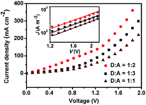
To deeply understand the optoelectronic properties of (TPACN)2Qx and have an insight into its PV performance, the hole-only devices were fabricated and measured to obtain the hole-mobility (μh) with the space charge limitation of current (SCLC) method (the details are described in the Experimental section).18 The μh is often regarded as one of the most important physical parameters for the design of PV donors, and it can be achieved in the dark with the structure of ITO/PEDOT:PSS/donor:PC61BM/Au. As a result, the J–V characteristics of the devices at different weight ratios (1![[thin space (1/6-em)]](https://www.rsc.org/images/entities/char_2009.gif) :
:![[thin space (1/6-em)]](https://www.rsc.org/images/entities/char_2009.gif) 1, 1
1, 1![[thin space (1/6-em)]](https://www.rsc.org/images/entities/char_2009.gif) :
:![[thin space (1/6-em)]](https://www.rsc.org/images/entities/char_2009.gif) 2 and 1
2 and 1![[thin space (1/6-em)]](https://www.rsc.org/images/entities/char_2009.gif) :
:![[thin space (1/6-em)]](https://www.rsc.org/images/entities/char_2009.gif) 3) are depicted in Fig. 7. Accordingly, the fitting plots of the data points in the SCLC regime are depicted in the inset of Fig. 7, and the μh data can be derived in the region with a slope of 2 as shown in Table 2.25 The pertinent μh values are 5.19 × 10⁻⁵, 1.29 × 10⁻⁴ and 8.66 × 10⁻⁵ cm2 V −1 s−1 for D/A ratios of 1
3) are depicted in Fig. 7. Accordingly, the fitting plots of the data points in the SCLC regime are depicted in the inset of Fig. 7, and the μh data can be derived in the region with a slope of 2 as shown in Table 2.25 The pertinent μh values are 5.19 × 10⁻⁵, 1.29 × 10⁻⁴ and 8.66 × 10⁻⁵ cm2 V −1 s−1 for D/A ratios of 1![[thin space (1/6-em)]](https://www.rsc.org/images/entities/char_2009.gif) :
:![[thin space (1/6-em)]](https://www.rsc.org/images/entities/char_2009.gif) 1, 1
1, 1![[thin space (1/6-em)]](https://www.rsc.org/images/entities/char_2009.gif) :
:![[thin space (1/6-em)]](https://www.rsc.org/images/entities/char_2009.gif) 2 and 1
2 and 1![[thin space (1/6-em)]](https://www.rsc.org/images/entities/char_2009.gif) :
:![[thin space (1/6-em)]](https://www.rsc.org/images/entities/char_2009.gif) 3, respectively, which keeps a consistent trend with their JSC and PCE values as expected. In contrast, the device based on a D/A ratio of 1
3, respectively, which keeps a consistent trend with their JSC and PCE values as expected. In contrast, the device based on a D/A ratio of 1![[thin space (1/6-em)]](https://www.rsc.org/images/entities/char_2009.gif) :
:![[thin space (1/6-em)]](https://www.rsc.org/images/entities/char_2009.gif) 2 possesses the optimal hole transporting capacity, in agreement with the greatest μh value among them. The results would probably give some valuable hints on the PV performance of devices and provide an important guide for developing new donor materials.
2 possesses the optimal hole transporting capacity, in agreement with the greatest μh value among them. The results would probably give some valuable hints on the PV performance of devices and provide an important guide for developing new donor materials.
Conclusions
In summary, a novel D–π–A–π–D-type OSM donor material, (TPACN)2Qx, containing Qx as the electrophilic core, was designed and synthesized for solution-processable OSCs. The excellent PCE of 6.25% has been achieved based on an optimized D/A ratio of 1![[thin space (1/6-em)]](https://www.rsc.org/images/entities/char_2009.gif) :
:![[thin space (1/6-em)]](https://www.rsc.org/images/entities/char_2009.gif) 2 using a simple spin-coating process from solution, which is the highest efficiency so far for solution-processed Qx-core based OSM BHJ-OSCs. The good PV performance is mainly attributed to the narrow Eg, lower HOMO energy level and high μh value caused by the effective electron-withdrawing property, relatively stable quinoid form of Qx and high hole-mobility capacity of (TPACN)2Qx-based devices. The impressive result demonstrates that OSM donors employing a quinoxaline derivative as the electrophilic unit can compete with their polymer counterparts. This study clearly indicates that Qx-based OSMs possess great potential for obtaining high performance solution-processed PV devices. Further device optimization is underway in our laboratory.
2 using a simple spin-coating process from solution, which is the highest efficiency so far for solution-processed Qx-core based OSM BHJ-OSCs. The good PV performance is mainly attributed to the narrow Eg, lower HOMO energy level and high μh value caused by the effective electron-withdrawing property, relatively stable quinoid form of Qx and high hole-mobility capacity of (TPACN)2Qx-based devices. The impressive result demonstrates that OSM donors employing a quinoxaline derivative as the electrophilic unit can compete with their polymer counterparts. This study clearly indicates that Qx-based OSMs possess great potential for obtaining high performance solution-processed PV devices. Further device optimization is underway in our laboratory.
Acknowledgements
This research was financially supported by the NSFC (No. 21102013, 21471024 and 21101020), the SRF from ROCS-SEM (No. 201001438 and 201001439) and the Fundamental Funds for the Central Universities (No. DUT16ZD205, DUT11LK20, DUT15ZD118 and DUT15LK20).Notes and references
- (a) P. Cheng and X. Zhan, Chem. Soc. Rev., 2016, 45, 2544–2582 RSC; (b) G. J. Hedley, A. Ruseckas and I. D. Samuel, Chem. Rev., 2017, 117, 796–837 CrossRef CAS PubMed; (c) K. Leo, Nat. Rev. Mater., 2016, 1, 16056, DOI:16010.11038/natrevmats.12016.16056.
- (a) A. W. Hains, Z. Liang, M. A. Woodhouse and B. A. Gregg, Chem. Rev., 2010, 110, 6689–6735 CrossRef CAS PubMed; (b) H. Kang, G. Kim, J. Kim, S. Kwon, H. Kim and K. Lee, Adv. Mater., 2016, 28, 7821–7861 CrossRef CAS PubMed.
- (a) J. C. Hummelen, B. W. Knight, F. LePeq and F. Wudl, J. Org. Chem., 1995, 60, 532–538 CrossRef CAS; (b) M. M. Wienk, J. M. Kroon, W. J. Verhees, J. Knol, J. C. Hummelen, P. A. van Hal and R. A. Janssen, Angew. Chem., Int. Ed., 2003, 42, 3371–3375 CrossRef CAS PubMed; (c) B. Kan, M. Li, Q. Zhang, F. Liu, X. Wan, Y. Wang, W. Ni, G. Long, X. Yang, H. Feng, Y. Zuo, M. Zhang, F. Huang, Y. Cao, T. P. Russell and Y. Chen, J. Am. Chem. Soc., 2015, 137, 3886–3893 CrossRef CAS PubMed; (d) M. Li, K. Gao, X. Wan, Q. Zhang, B. Kan, R. Xia, F. Liu, X. Yang, H. Feng, W. Ni, Y. Wang, J. Peng, H. Zhang, Z. Liang, H.-L. Yip, X. Peng, Y. Cao and Y. Chen, Nat. Photonics, 2016, 11, 85–90 CrossRef; (e) Y. Liu, L. A. Renna, M. Bag, Z. A. Page, P. Kim, J. Choi, T. Emrick, D. Venkataraman and T. P. Russell, ACS Appl. Mater. Interfaces, 2016, 8, 7070–7076 CrossRef CAS PubMed.
- (a) Y. Lin, Y. Li and X. Zhan, Chem. Soc. Rev., 2012, 41, 4245–4272 RSC; (b) O. Ostroverkhova, Chem. Rev., 2016, 116, 13279–13412 CrossRef CAS PubMed; (c) B. Walker, C. Kim and T.-Q. Nguyen, Chem. Mater., 2011, 23, 470–482 CrossRef CAS.
- D. Deng, Y. Zhang, J. Zhang, Z. Wang, L. Zhu, J. Fang, B. Xia, Z. Wang, K. Lu, W. Ma and Z. Wei, Nat. Commun., 2016, 7, 13740, DOI:13710.11038/ncomms13740.
- Y. Yang, Z. G. Zhang, H. Bin, S. Chen, L. Gao, L. Xue, C. Yang and Y. Li, J. Am. Chem. Soc., 2016, 138, 15011–15018 CrossRef CAS PubMed.
- Y. Li, Q. Guo, Z. Li, J. Pei and W. Tian, Energy Environ. Sci., 2010, 3, 1427–1436 CAS.
- (a) H. Gao, Y. Li, L. Wang, C. Ji, Y. Wang, W. Tian, X. Yang and L. Yin, Chem. Commun., 2014, 50, 10251–10254 RSC; (b) C. Ji, L. Yin, K. Li, L. Wang, X. Jiang, Y. Sun and Y. Li, RSC Adv., 2015, 5, 31606–31614 RSC; (c) L. Wang, L. Yin, C. Ji and Y. Li, Dyes Pigm., 2015, 118, 37–44 CrossRef CAS.
- (a) C. Ji, L. Yin, L. Wang, T. Jia, S. Meng, Y. Sun and Y. Li, J. Mater. Chem. C, 2014, 2, 4019–4026 RSC; (b) L. Wang, L. Yin, C. Ji, Y. Zhang, H. Gao and Y. Li, Org. Electron., 2014, 15, 1138–1148 CrossRef CAS.
- S. Zeng, L. Yin, C. Ji, X. Jiang, K. Li, Y. Li and Y. Wang, Chem. Commun., 2012, 48, 10627–10629 RSC.
- S. Paek, N. Cho, K. Song, M.-J. Jun, J. K. Lee and J. Ko, J. Phys. Chem. C, 2012, 116, 23205–23213 CAS.
- (a) D. W. Chang, S.-J. Ko, J. Y. Kim, L. Dai and J.-B. Baek, Synth. Met., 2012, 162, 1169–1176 CrossRef CAS; (b) Y. Lee, Y. M. Nam and W. H. Jo, J. Mater. Chem., 2011, 21, 8583–8590 RSC; (c) H. J. Song, T. H. Lee, M. H. Han, J. Y. Lee and D. K. Moon, Polymer, 2013, 54, 1072–1079 CrossRef CAS.
- (a) M. L. Keshtov, S. A. Kuklin, N. A. Radychev, I. E. Ostapov, A. Y. Nikolaev, I. O. Konstantinov, M. M. Krayushkin, E. N. Koukaras, A. Sharma and G. D. Sharma, RSC Adv., 2016, 6, 71232–71244 RSC; (b) C. Lee, Y. Li, W. Lee, Y. Lee, J. Choi, T. Kim, C. Wang, E. D. Gomez, H. Y. Woo and B. J. Kim, Macromolecules, 2016, 49, 5051–5058 CrossRef CAS; (c) Z. Lu, C.-h. Li, C. Du, X. Gong and Z.-s. Bo, Chin. J. Polym. Sci., 2013, 31, 901–911 CrossRef CAS; (d) R. Singh, G. Pagona, V. G. Gregoriou, N. Tagmatarchis, D. Toliopoulos, Y. Han, Z. Fei, A. Katsouras, A. Avgeropoulos, T. D. Anthopoulos, M. Heeney, P. E. Keivanidis and C. L. Chochos, Polym. Chem., 2015, 6, 3098–3109 RSC; (e) E. Wang, L. Hou, Z. Wang, Z. Ma, S. Hellström, W. Zhuang, F. Zhang, O. Inganäs and M. R. Andersson, Macromolecules, 2011, 44, 2067–2073 CrossRef CAS; (f) Y. Zhang, J. Zou, H.-L. Yip, K.-S. Chen, D. F. Zeigler, Y. Sun and A. K. Y. Jen, Chem. Mater., 2011, 23, 2289–2291 CrossRef CAS.
- (a) H.-C. Chen, Y.-H. Chen, C.-C. Liu, Y.-C. Chien, S.-W. Chou and P.-T. Chou, Chem. Mater., 2012, 24, 4766–4772 CrossRef CAS; (b) D. Liu, W. Zhao, S. Zhang, L. Ye, Z. Zheng, Y. Cui, Y. Chen and J. Hou, Macromolecules, 2015, 48, 5172–5178 CrossRef CAS; (c) J. Yuan, L. Qiu, Z. Zhang, Y. Li, Y. He, L. Jiang and Y. Zou, Chem. Commun., 2016, 52, 6881–6884 RSC.
- (a) X. Li, Y. Zhou, J. Chen, J. Yang, Z. Zheng, W. Wu, J. Hua and H. Tian, Chem. Commun., 2015, 51, 10349–10352 RSC; (b) K. Pei, Y. Wu, A. Islam, S. Zhu, L. Han, Z. Geng and W. Zhu, J. Phys. Chem. C, 2014, 118, 16552–16561 CrossRef CAS; (c) K. Pei, Y. Wu, H. Li, Z. Geng, H. Tian and W. H. Zhu, ACS Appl. Mater. Interfaces, 2015, 7, 5296–5304 CrossRef CAS PubMed; (d) J. Yang, P. Ganesan, J. Teuscher, T. Moehl, Y. J. Kim, C. Yi, P. Comte, K. Pei, T. W. Holcombe, M. K. Nazeeruddin, J. Hua, S. M. Zakeeruddin, H. Tian and M. Grätzel, J. Am. Chem. Soc., 2014, 136, 5722–5730 CrossRef CAS PubMed.
- (a) D. Kekuda, J.-S. Huang, M. Velusamy, J. T. Lin and C.-W. Chu, Sol. Energy Mater. Sol. Cells, 2010, 94, 1767–1771 CrossRef CAS; (b) W. Li, D. Wang, S. Wang, W. Ma, S. Hedström, D. I. James, X. Xu, P. Persson, S. Fabiano, M. Berggren, O. Inganäs, F. Huang and E. Wang, ACS Appl. Mater. Interfaces, 2015, 7, 27106–27114 CrossRef CAS PubMed; (c) J. A. Mikroyannidis, A. N. Kabanakis, A. Kumar, S. S. Sharma, Y. K. Vijay and G. D. Sharma, Langmuir, 2010, 26, 12909–12916 CrossRef CAS PubMed.
- (a) Z. Li, Y. Zhang, A. L. Holt, B. P. Kolasa, J. G. Wehner, A. Hampp, G. C. Bazan, T.-Q. Nguyen and D. E. Morse, New J. Chem., 2011, 35, 1327–1334 RSC; (b) C.-Y. Yu, C.-P. Chen, S.-H. Chan, G.-W. Hwang and C. Ting, Chem. Mater., 2009, 21, 3262–3269 CrossRef CAS.
- (a) P. W. M. Blom, M. J. M. de Jong and M. G. van Munster, Phys. Rev. B: Condens. Matter, 1997, 55, R656–R659 CrossRef CAS; (b) Z. Li, Q. Dong, Y. Li, B. Xu, M. Deng, J. Pei, J. Zhang, F. Chen, S. Wen, Y. Gao and W. Tian, J. Mater. Chem., 2011, 21, 2159–2168 RSC.
- Q. Peng, J. Xu and W. Zheng, J. Polym. Sci., Part A: Polym. Chem., 2009, 47, 3399–3408 CrossRef CAS.
- (a) Y. Chen, C. Li, P. Zhang, Y. Li, X. Yang, L. Chen and Y. Tu, Org. Electron., 2013, 14, 1424–1434 CrossRef CAS; (b) F. Liang, J. Lu, J. Ding, R. Movileanu and Y. Tao, Macromolecules, 2009, 42, 6107–6114 CrossRef CAS.
- Y. Cui, P. Li, C. Song and H. Zhang, J. Phys. Chem. C, 2016, 120, 28939–28950 CAS.
- R. Chen, Y. Wang, T. Chen, H. Li, C. Zheng, K. Yuan, Z. Wang, Y. Tao, C. Zheng and W. Huang, J. Phys. Chem. B, 2015, 119, 583–591 CrossRef CAS PubMed.
- S. So, H. Choi, C. Kim, N. Cho, H. M. Ko, J. K. Lee and J. Ko, Sol. Energy Mater. Sol. Cells, 2011, 95, 3433–3441 CrossRef CAS.
- Q. Liu, Y. Liu, Y. Wang, L. Ai, X. Ouyang, L. Han and Z. Ge, New J. Chem., 2013, 37, 3627–3633 RSC.
- L. Wang, L. Yin, L. Wang, B. Xie, C. Ji and Y. Li, Dyes Pigm., 2017, 140, 203–211 CrossRef CAS.
Footnotes |
| † Electronic supplementary information (ESI) available: Synthetic procedures, NMR spectra, computational electronic transitions of the synthesized compounds and AFM images of blend films. See DOI: 10.1039/c7ra01859b |
| ‡ The authors have equal contribution to the manuscript. |
| This journal is © The Royal Society of Chemistry 2017 |

