DOI:
10.1039/C7RA01617D
(Paper)
RSC Adv., 2017,
7, 18068-18074
Theoretical exploration on the electronic and magnetic properties of (FeCp)n – (n = 1, 2) ligand-functionalized graphene†
Received
8th February 2017
, Accepted 13th March 2017
First published on 24th March 2017
Abstract
Using first principles calculations, we systematically studied the electronic and magnetic properties of half sandwich organometallic ligand-functionalized single layer graphene, (FeCp)n@SLGs (n = 1, 2), with different adsorption sites and coverage concentrations. Our results show that all the (FeCp)n@SLGs are quite stable having high binding energies. Except the nonmagnetic FeCp@G44-S1, all the complexes are found to be robust ferromagnets. In particular, the magnetic moments of (FeCp)2@G33-D1, (FeCp)2@G33-D2, (FeCp)2@G33-D3 and (FeCp)2@G44-D1 per unit cell are as large as 2.0 μB, 1.64 μB, 2.0 μB and 1.30 μB, respectively. Among the studied systems, spin polarized band gaps are opened in the Dirac points of FeCp@G33-S, (FeCp)2@G33-D1, (FeCp)2@G44-S2, (FeCp)2@G44-S3, and (FeCp)2@G44-D5, in which (FeCp)2@G33-D1 is transformed into an intrinsic semiconductor. Moreover, displacing Fe by Co or Ni element is found to induce an increasement in magnetic moment or induce a transition from metal to half metal.
1. Introduction
Graphene, which is a two-dimensional single-atom-thick material, exhibits unusual electronic properties1–8 and has attracted great attention due to its potential application as a building block of nanoelectronic devices. However, the realization of graphene's commercial applications has to overcome two primary obstacles: (i) the synthesis of high-quality graphene on a large scale, and (ii) producing a band gap in graphene to replace silicon in future, which is the biggest challenge. Great efforts have been made to overcome the proposed challenges and various strategies have been proposed for the synthesis of graphene, such as mechanical peeling of graphite,2 ultrasonic exfoliation,9 chemical reduction of graphite oxide (GO)10 and chemical vapor decomposition (CVD) growth on transition metal surfaces.11–14 Particularly, the CVD method has been proven to be an effective way to meet the requirement of overcoming challenge (i). For challenge (ii), a number of solutions have been proposed by theoretical and experimental studies. One straightforward method is to combine various graphene/X heterostructures,15,16 e.g. a 0.26 eV band gap is obtained by placing graphene on a SiC surface.15 Another is substitutional doping with exotic elements (e.g. B and N),17–19 e.g. the band gap of graphene is found to increase linearly with the doped BN concentration.18 In addition, the quantum confinement effect by cutting graphene into nanoribbons19,20 has also been demonstrated as a way to the open the gap of graphene. Alternatively, chemical/physical adsorption has been proven to be a simple and effective solution to tune the electronic properties of graphene,21–30 in which the approach of loading half organo-transition metal (TM) ligands (OTMLs) on graphene substrates has been theoretically explored.25–29 The adsorption of OTMLs on graphene has two significant advantages: (i) compared with two-end closed organometallic sandwich clusters,31–33 the bonding between half TMnOLs and graphene is stronger due to coordinate d–π bonding. For example, the chemical attachment of a C60 fullerene on graphene is not energetically feasible,24 whereas connecting graphene and C60 using a bridging Cr atom can largely enhance the binding energy;25 (ii) with single TM atom adsorbed graphene, e.g. TM@Gs,34–39 the existence of organic ligands has the advantage of shielding the clustering and oxidation of the metal atoms. Indeed, OTMLs-functionalized graphene introduces versatile electronic properties, for example, the covalent bonding of TMBz to graphene opens up a 0.81 eV band gap26 and induces a high magnetization energy.27 In our previous studies, a density related band gap was observed for TMBz-functionalized graphene.28,29
Compared with hexagonal hydrocarbon organic ligands (e.g. benzene), the bonding of TM atoms with the cyclopentadienyl (Cp = C5H5) ligand was found to display different bonding mechanisms due to the fact that it has one less valence electron.31 Herein, we present a systematic theoretical study on the structural, electronic and magnetic properties of FeCp ligands-adsorbed graphene. For comparison, 3 × 3 and 4 × 4 graphene supercells with single-side and double-side adsorption are considered. Our results show that most systems are ferromagnetic in their ground states with the exception of FeCp@G44-S1. All the (FeCp)n@G33s and a number of (FeCp)n@G44s have a spin dependent band gap in the Dirac point. Particularly, (FeCp)2@G33-D1 is transformed into an intrinsic semiconductor. Moreover, displacing Fe by Co or Ni elements is found to induce an increase in magnetic moments or induce a metallic properties transition.
2. Computational methodology and models
All calculations are performed within the framework of spin polarized DFT as implemented in the Vienna Ab initio Simulation Package (VASP).40,41 The exchange–correlation potentials are treated by the generalized gradient approximation (GGA) parametrized by Perdew, Burke, and Ernzerholf (PBE).42 The interaction between valence electrons and ion cores is described by the projected augmented wave (PAW) method.43,44 In order to consider the local coulomb interaction in the 3d orbitals of the TM atom, we incorporated an effective on-site coulomb interaction for the 3d states of TM atoms using the GGA+U (U = 4 eV and J = 0.9 eV) method. Furthermore, the DFT-D2, method taking into account the van der Waals (vdW) interaction, was adopted.45 Both 3 × 3 (G33) and 4 × 4 (G44) slabs with the lattice parameters of a = b = 7.41 Å and 9.88 Å, respectively, were used for the adsorption blocks. Accordingly, the Monkhorst–Pack grids of 13 × 13 × 1 and 9 × 9 × 1 were used for the (FeCp)n@G33s and (FeCp)n@G44s (n = 1, 2) geometry optimization, respectively. Moreover, much denser k-point grids of 25 × 25 × 1 to 23 × 23 × 1 were used for electronic properties exploration. To eliminate the interaction between the entities of neighbouring unit cells, the lattice parameters along the z axis were set as large as 15 Å and 18 Å for the single-side/two-side adsorbed systems. Moreover, a cutoff of 400 eV was used for the plane wave expansion of the wave function to converge the relevant quantities. Structure relaxations were carried out until all the atomic forces on each ion were less than 0.01 eV Å−1.
3. Results and discussion
3.1 Structural, electronic and magnetic properties of (FeCp)n@G33s, n = 1, 2
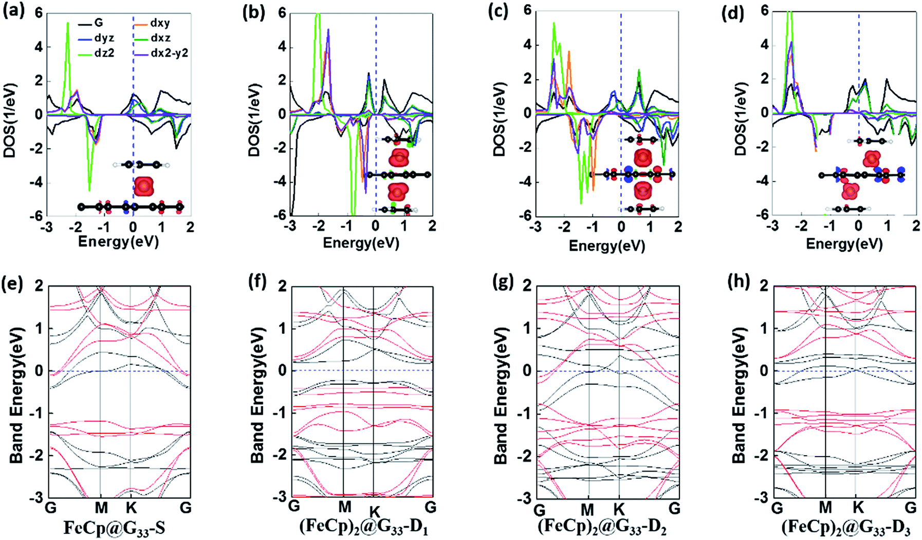
3.1.1 Geometries and stabilities. A total of four configurations were prepared for (FeCp)n@G33s: (i) FeCp@G33-S, in which one FeCp ligand is adsorbed on the hollow site of graphene (see Fig. 1a and e); (ii) (FeCp)2@G33-D1, in which two FeCp ligands are adsorbed on opposite sides and same hollow site of graphene (see Fig. 1b and f); (iii) (FeCp)2@G33-D2, isomer of configuration (ii) with two FeCp ligands adsorbed on the adjacent hollow sites of graphene (see Fig. 1c and g); and (iv) (FeCp)2@G33-D3, isomer of configurations (ii) and (iii) by binding the two FeCp ligands on the hollow sites spaced by one line of hexagons (see Fig. 1d and h). It is found that most of the (FeCp)n@G33s have normal sandwich configurations. An exception is found for (FeCp)2@G33-D1, in which one FeCp ligand slightly deviates from the hollow site of graphene due to the coulomb repulsion (see Fig. 1b). The C–C and C–H bond lengths of the Cp ligands are in the range of 1.43–1.44 Å and 1.09–1.10Å, respectively, whereas the C–C bond lengths of graphene are around 1.42–1.44 Å (see Table S1 in the (ESI†)). Moreover, the C–C bond lengths of graphene close to the Fe atom are a bit longer than those that are far away due to the local π(G)–d(Fe) interaction. For example, the graphene C–C bond lengths of the carbon hexagon facing the Fe atom are in the range of 1.43–1.44 Å, whereas those located around are about 1.42 Å. Moreover, the Fe atoms are at a distance from the mass center of the Cp ligands (DFe–Cp) and graphene (DFe–G) in the range of 1.69–1.76 Å and 1.60–1.69 Å, respectively (see Table 1), among which, the DFe–Cps distances are a bit longer than that of DFe–Gs. Distinct geometric characters are derived from the different bonding characters, in which the charges donated to graphene are much smaller than that of Cp ligand (see Table 1 and Fig. 2e–j), leading to a more ionic bonding character of Fe–Cp and more covalent bonding characters of Fe–graphene. Different from the FeBz@G isomer,28 the DFe–Cp of FeCp@G33-S is a bit larger, ∼1.76 Å, whereas a different case is verified for that of DFe–G, ∼1.64 Å. Compared with that of FeCp@G33-S, the DFe–G of (FeCp)2@G33-D1 is much larger, ∼1.69 Å, whereas for the (FeCp)2@G33-D2 and (FeCp)2@G33-D3 isomers, the DFe–Gs are reduced sharply to 1.60 Å (see Table 1).
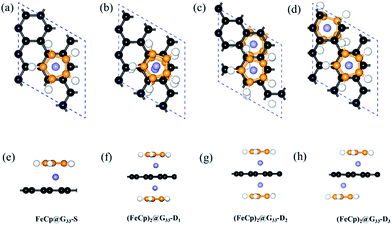 |
| | Fig. 1 Top and side views of the optimized structures of FeCp@G33-S (a and e), (FeCp)2@G33-D1 (b and f), (FeCp)2@G33-D2 (c and g), and (FeCp)2@G33-D3 (d and h). Black and orange balls represent the carbon atoms of graphene and Cp ligands; and white and purple balls represent H and Fe atoms, respectively. The complete descriptions of (FeCp)2@G33-D2 (c) and (FeCp)2@G33-D3 (d) are depicted in the 2 × 2 supercells in Fig. S1(a, b, e and f) in the ESI.† | |
Table 1 Systems (Sys), the distance of the Fe atom to Cp ligands (DFe–Cp) and graphene (DFe–G), charges transferred from Fe atom to graphene (Δe), binding energies (Eb), magnetic moments (MM) and the band gaps at the Dirac point (Δg) of FeCp@G33s and FeCp@G44s
| Sys |
DFe–Cp (Å) |
DFe–G (Å) |
Δe (e) |
Eb (kJ mol−1) |
MM (μB) |
Δg (eV) |
| FeCp@G33-S |
1.76 |
1.64 |
0.44 |
271.6 |
0.81 |
0.78 |
| (FeCp)2@G33-D1 |
1.71 |
1.69, 1.69 |
0.72 |
256 |
2.00 |
0.40 |
| (FeCp)2@G33-D2 |
1.69 |
1.60 |
0.83 |
277.6 |
1.64 |
0 |
| (FeCp)2@G33-D3 |
1.73 |
1.60 |
0.80 |
278.7 |
2.00 |
0.61 |
| FeCp@G44-S1 |
1.68 |
1.60 |
0.58 |
285.9 |
0 |
0 |
| (FeCp)2@G44-S2 |
1.68 |
1.62 |
0.94 |
256.6 |
0.74 |
0.25 |
| (FeCp)2@G44-S3 |
1.77, 1.64 |
1.61, 1.42 |
0.99 |
270.8 |
0.94 |
0.12 |
| (FeCp)2@G44-D1 |
1.68 |
1.65 |
0.87 |
257.4 |
1.30 |
0 |
| (FeCp)2@G44-D2 |
1.67 |
1.60 |
0.77 |
277.8 |
0.97 |
0 |
| (FeCp)2@G44-D3 |
1.58 |
1.65, 1.69 |
1.06 |
281 |
0.50 |
0 |
| (FeCp)2@G44-D4 |
1.65 |
1.58 |
1.02 |
280.4 |
0.49 |
0 |
| (FeCp)2@G44-D5 |
1.65 |
1.58 |
1.03 |
277.6 |
0.61 |
0.25 |
 |
| | Fig. 2 Binding energies (a and b) and total magnetic moments (c and d) of (FeCp)n@G33s and (FeCp)n@G44s, n = 1, 2. CDD plots of FeBz@G33-S (e), FeBz@G44-S (f), FeCp@G33-S (g), FeCp@G44-S (h), (FeCp)2@G33-D1 (i) and (FeCp)2@G33-D2 (j). | |
To verify the structural stabilities of (FeCp)n@SLGs, we calculated the binding energies, which are defined as follows:
| Eb = −(E(FeCp)n@SLG − nECp − nEFe − EG)/n |
where
E[·] represents the total energy of (FeCp)
n@SLGs, the Cp ligands, Fe atom and pristine graphene, and
n is the number of FeCp ligands. Our results show that the binding energies of all the studied FeCp@G
33s are positive and range from 256 kJ mol
−1 to 285.9 kJ mol
−1, which is much larger than that of the FeBz@G isomer (211 kJ mol
−1),
28 where such large binding energies show that the chemical attachment dominates the FeCp ligands and graphene interaction. As shown in the charge density difference plots (CDDs) (
Fig. 2e–j), the electron densities around the graphene in FeCp@SLGs (see
Fig. 2g and h) is much higher than that of FeBz@G
33 and FeBz@G
44 (see
Fig. 2e and f), which indicates a more covalent bonding character of FeCp@SLGs. The binding energies of FeCp@G
33-S, (FeCp)
2@G
33-D
2 and (FeCp)
2@G
33-D
3 are 271.6 kJ mol
−1, 277.6 kJ mol
−1 and 278.7 kJ mol
−1, respectively. In contrast, the binding energy of (FeCp)
2@G
33-D
1 is a bit smaller, ∼256 kJ mol
−1 (see
Fig. 2a and
Table 1). Such distinct binding characters can be simply understood from the electron transfer between Fe atoms and graphene. On one hand, with an increase in the distance between two FeCp ligands, the total charges transferred from the Fe atom to graphene also increase (see
Table 1), resulting in an enhancement in the covalent bonding between the Fe atom and graphene. On the other hand, such energetic characters agree well with the Fe–G distances discussed above, that is, the larger FeCp ligand distances in (FeCp)
2@G
33-D
2 and (FeCp)
2@G
33-D
3 cause their coulomb repulsion to decrease, which is the cause of their shorter Fe–graphene distances and larger stabilities.
3.1.2 Electronic and magnetic properties. Different from pristine graphene, the incorporation of FeCp ligands in (FeCp)n@G33s causes it to become ferromagnetic (FM) (see Fig. 2c). The magnetic moments of FeCp@G33-S, (FeCp)2@G33-D1, (FeCp)2@G33-D2 and (FeCp)2@G33-D3 are 0.81 μB, 2.00 μB, 1.64 μB and 2.00 μB, respectively, in which the local magnetic moments of the Fe atoms are 0.73 μB, 1.07/1.09 μB, 0.82/0.82 μB, and 1.04/1.02 μB, respectively. Moreover, the antiferromagnetic (AFM) states are also extended, in which the AFM state of (FeCp)2@G33-D1 is 0.10 eV higher in energy than the FM state. The calculated density of states projected onto the atomic orbitals is plotted in Fig. 3a–d. In (FeCp)n@G33s, the states around the Fermi energy level are mainly contributed by the d electrons of the Fe atom, which indicates that the magnetic moments of the studied systems are mainly contributed by the unpaired d electrons of the Fe atom. Corresponding to FeBz@SLG (2.0 μB),26,28 the magnetic moment of FeCp@G33-S is largely reduced. As shown in Fig. S3 in the ESI,† the dxz electron on the major channel is shifted above the Fermi level, which leads to decrease in the magnetic moment by about 1 μB. Except for (FeCp)2@G33-D2, the spin polarized band gaps are opened in the Dirac points of graphene for the other three systems (see Fig. 3e–h), i.e., the band gaps are about 0.78 eV, 0.40 eV and 0.61 eV for FeCp@G33-S, (FeCp)2@G33-D1 and (FeCp)2@G33-D3, respectively. Particularly, (FeCp)2@G33-D1 is completely transformed into an intrinsic semiconductor, whereas (FeCp)2@G33-S and (FeCp)2@G33-D3 can be regarded as n-type semiconductors and can be produced to be intrinsic semiconductors by shifting their Fermi levels into the band gap.
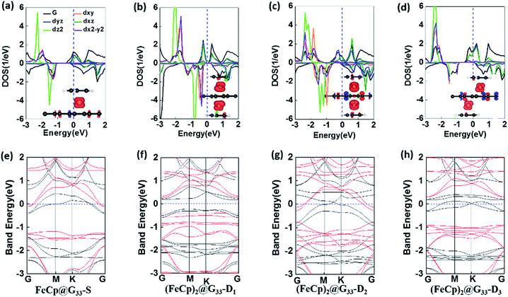 |
| | Fig. 3 (a–d) Projected density of states (DOS) and (e–h) electronic band structures of (FeCp)n@G33s, n = 1, 2. The black and red lines correspond to the spin-up and spin-down channels, respectively. Insets are the spin densities plots. | |
3.2 Structural, electronic and magnetic properties of (FeCp)n@G44s, n = 1, 2
3.2.1 Geometries and stabilities. Similar to (FeCp)n@G33s, eight different configurations are considered for the (FeCp)n@G44s isomers: (i) FeCp@G44-S1, in which the Fe atom is fixed on the hollow site of graphene (see Fig. S2a and d in the ESI†); (ii) (FeCp)2@G44-S2, in which two FeCp ligands are adsorbed on adjacent hollow sites in the graphene slab, forming two FeCp-lines along one zigzag edge of graphene spaced by three rows of hexagons (see Fig. S2b and e in the ESI†); (iii) (FeCp)2@G44-S3, isomer of configuration (ii) with the FeCp ligands forming a large hexagonal loop (see Fig. S2c and f in the ESI†); (iv) (FeCp)2@G44-D1, isomer of (FeCp)2@G33-D1 (see Fig. 4a and f) with the G33 slab displaced by a G44 slab; (v) (FeCp)2@G44-D2, isomer of (FeCp)2@G33-D2 (see Fig. 4b and g); (vi) (FeCp)2@G44-D3, isomer of (FeCp)2@G33-D3 (see Fig. 4c and h); (vii) (FeCp)2@G33-D3, isomer of (FeCp)2@G33-D3 (see Fig. 4d and i); and (viii) (FeCp)2@G44-D5, isomer of configuration (iv)–(vii) having two-side FeCp ligands spaced by three carbon hexagons (see Fig. 4e and j).
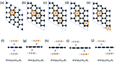 |
| | Fig. 4 (a–j) Top and side views of the optimized structures of (FeCp)2@G44-Dis, i = 1–5. Black and orange balls represent the carbon atoms of graphene and Cp ligands; and white and purple balls represent H and Fe atoms, respectively. The complete descriptions of (FeCp)2@G44-D4 (c) and (FeCp)2@G44-D5 (d) are depicted in the 2 × 2 supercells in Fig. S1(c, d, g and f) in the ESI.† | |
Significant geometry distortions are found for the FeCp ligands in (FeCp)2@G44-S2 and (FeCp)2@G44-S3 (see Fig. S2b, c, e and f†), that is, the adjacent Cp ligands are largely tilted with the inclination angles of ∼10° due to the van der Waals interaction. Differently, normal sandwich configurations are favoured for all the other systems. The C–C bond lengths of the Cp ligands and graphene are about 1.42–1.44 Å and 1.41–1.45 Å (see Table S1 in the ESI†), respectively. DFe–Cps and DFe–Gs are in the range of 1.68–1.71 Å and 1.60–1.65 Å, respectively. Different from FeCp@G44-S1, the DFe–Gs of FeCp@G44-S2,3 and (FeCp)2@G44-Ds are a bit longer due to the enhanced atom electrostatic interaction of the FeCp ligands (see Table 1). All the (FeCp)n@G44s are chemically stable with high binding energies of 256.6–285.9 kJ mol−1. Among them, (FeCp)2@G44-S1 has the largest binding energy of ∼285.9 kJ mol−1, followed by (FeCp)2@G44-D3 and (FeCp)2@G44-D4 with values of ∼281 kJ mol−1. In contrast, (FeCp)2@G44-S2 has the smallest binding energy of 256.6 kJ mol−1. On one hand, the stability of these FeCp@SLGs isomers is slightly dependent on the coverage concentration. For example, the binding energies of (FeCp)2@G33-D1 and (FeCp)2@G44-D1 are 256 kJ mol−1 and 257.4 kJ mol−1, respectively, whereas that of (FeCp)2@G33-D2 and (FeCp)2@G44-D2 is 277.6 kJ mol−1 and 277.8 kJ mol−1, respectively. On the other hand, the stabilities of these (FeCp)n@G44s are largely dependent on the relative positions of FeCp ligands. For example, the binding energies of (FeCp)2@G44-S2, (FeCp)2@G44-S3 and (FeCp)2@G44-D1 per unit cell are much smaller than that of FeCp@G44-Di (i = 3, 4 and 5) by about 13–24 kJ mol−1.
3.2.2 Electronic and magnetic properties. Except (FeCp)2@G44-S1, which is nonferromagnetic, all the other (FeCp)n@G44s systems have ferromagnetic ground states, in which the AFM state of (FeCp)2@G44-D1 is less stable since it is about 0.11 eV higher in energy. Similar to (FeCp)2@G33-D1, (FeCp)2@G44-D1 has the largest magnetic moment of ∼1.30 μB, whereas that of (FeCp)2@G44-S2, (FeCp)2@G44-S3 and (FeCp)2@G44-D2 are 0.74 μB, 0.94 μB and 0.97 μB, respectively. As for the others, their magnetic moments are relative smaller, which are about 0.50 μB, 0.49 μB and 0.61 μB for (FeCp)2@G44-Di (i = 3, 4 and 5) respectively. Similar to (FeCp)n@G33s, the ferromagnetic properties of these FeCp@SLGs are mainly derived from the unpaired d electrons of the Fe atoms (see Fig. 5f–j, S4†). Moreover, spin polarized band structures are found for a few (FeCp)n@G44s systems, in which a band gap of 0.25 eV, 0.12 eV and 0.36 eV is opened in the Dirac point for (FeCp)2@G44-S2 (FeCp)2@G44-S3 and (FeCp)2@G44-D5 due to the breaking of the intrinsic electronic symmetry of pristine graphene. The electronic properties of these (FeCp)n @SLGs are largely sensitive to the adsorption densities of the FeCp ligands. For example, the n-type semiconducting FeCp@G33-S/(FeCp)2@G33-D1 and the semiconducting (FeCp)2@G33-D1 are completely transformed into metals in their (FeCp)@G44s isomers (see Table 2).
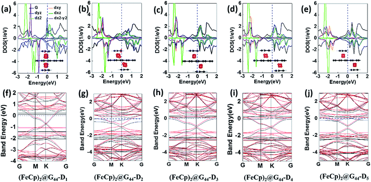 |
| | Fig. 5 (a–e) Density of states (DOS) and (f–j) band structure plots of (FeCp)2@G44s. Insets are the spin densities plots. | |
Table 2 Systems (Sys), the distance of the TM atom to Cp ligands (DTM–Cp) and graphene (DTM–G), charges transferred from the Fe atom to graphene (Δe), binding energies (Eb), magnetic moments (MM) and band gaps (Δg) at the Dirac point of (CoCp)n@Gs and (NiCp)n@Gs
| Sys |
DFe–Cp (Å) |
DFe–G (Å) |
Δe (e) |
Eb (kJ mol−1) |
MM (μB) |
Δg (eV) |
| CoCp@G44-S1 |
1.80 |
1.70 |
0.28 |
178.3 |
1.94 |
0 |
| (CoCp)2@G44-S2 |
1.79, 1.80 |
1.86, 1.86 |
0.50 |
164.4 |
3.92 |
2.0 |
| (CoCp)2@G44-D1 |
1.71, 1.75 |
1.68, 1.68 |
0.55 |
172.8 |
3.81 |
1.83 |
| (NiCp)2@G33-D1 |
1.75, 1.75 |
1.97, 2.03 |
0.36 |
259.1 |
2.0 |
2 |
| NiCp@G44-S1 |
1.76 |
1.93 |
0.18 |
249.7 |
1.0 |
0 |
| (NiCp)2@G44-S2 |
1.76, 1.77 |
2.06, 2.01 |
0.38 |
248.8 |
2.0 |
0.74 |
| (NiCp)2@G44-D5 |
1.76, 1.76 |
1.93, 1.90 |
0.40 |
248.7 |
2.0 |
0.94 |
3.3 Structural, electronic and magnetic properties of other (TMCp)n@Gs, n = 1, 2, TM = Co, Ni
For comparison, we studied the electronic and magnetic properties of a number of (TMCp)n@SLGs (n = 1, 2), TM = Co, Ni (see Fig. S5 and S6 in the ESI†). Different from (FeCp)n@SLGs, the Ni atoms prefer to sit close to the top site of graphene (see Fig. S6 in the ESI†) due to their stable valence electron configuration (3d104s2). Regarding (FeCp)n@SLGs, the binding energies of (CoCp)n@SLGs and (NiCp)n@SLGs are relative smaller, which are around 164.4–178.3 kJ mol−1 and 248.7–259.1 kJ mol−1, respectively (see Table 2). This is due to the fact that the charges transferred from Co/Ni to graphene are much smaller than that of the Fe atoms (see Table 2 and Fig. S7 in the ESI†). On the other hand, different from (CoCp)n@SLGs and FeCp@SLGs, the charge distribution on the Ni atoms and graphene in NiCp@Gs is uneven, leading to their distinct interactions between the single-side adsorption and double-side adsorption.
Furthermore, the electronic and magnetic properties of these TMCp ligands-functionalized graphene are also dependent on the TM element. Different from (FeCp)n@s, the magnetic moments of (CoCp)n@Gs and (NiCp)n@Gs are almost not affected by the adsorption position of the TMCp ligand. For example, the magnetic moments per unit cell are 1.94 μB, 3.92 μB and 3.81 μB for CoCp@G44-S1, (CoCp)2@G44-S2 and (CoCp)2@G44-D1, respectively (see Table 2). As for the (NiCp)n@Gs isomers, their magnetic moments are 1.0 μB for NiCp@G44-S1 and 2.0 μB for (NiCp)2@G44-S2, (NiCp)2@G44-D1 and (NiCp)2@G44-D5. The AFM states of (NiCp)2@G33-D1 and (CoCp)2@G44-D1 are less stable than that of the FM state by about 0.13 eV and 0.12 eV higher in energy. On the other hand, CoCp@G44-S1, (CoCp)2@G44-D1 (see Fig. S8d and f in the ESI†) and (NiCp)2@G33-D1 (see Fig. S9g in the ESI†) are metals. Differently, NiCp@G44-S1 is an intrinsic semiconductor with a band gap of 0.17 eV (see Fig. S9e in the ESI†). The others, (CoCp)2@G44-S2 (see Fig. S8e in the ESI†), (NiCp)2@G44-S2 (see Fig. S9f in the ESI†) and (NiCp)2@G44-D5 (see Fig. S9h in the ESI†) are half metals with half metal band gaps of 0.24 eV, 0.13 eV and 0.29 eV, respectively, which can be used for spintronic device applications.
4. Conclusions
The electronic and magnetic properties of half organic–metal sandwich ligands-functionalized monolayer graphene, (FeCp)n@SLGs (n = 1, 2), are systematically studied. All the (FeCp)n@SLGs are thermodynamically stable with the covalent bonding of TMCp ligands to graphene. Versatile electronic and magnetic properties are found for (FeCp)n@SLGs, depending on the adsorption sites and coverage concentrations. Particularly, (FeCp)2@G33-D1 is transformed into an intrinsic semiconductor with a band gap of 0.40 eV due to the breaking of the intrinsic electronic symmetry of pristine graphene. By displacing Fe by Co or Ni elements, distinct changes to the magnetic and electronic properties are found.
Acknowledgements
This study is supported by the NSFC (11574262, 11647316, 21503006). The authors thank the computational resources at the YZU.
References
- W. Han, R. K. Kawakami, M. Gmitra and J. Fabian, Nat. Nanotechnol., 2014, 9, 794–807 CrossRef CAS PubMed.
- K. S. Novoselov, A. K. Geim, S. V. Morozov, D. Jiang, Y. Zhang, S. V. Dubonos, I. V. Grigorieva and A. A. Firsov, Science, 2004, 306, 666–669 CrossRef CAS PubMed.
- Y. Xu, Z. Li and W. Duan, Small, 2014, 10, 2182–2199 CrossRef CAS PubMed.
- Y. Zhang, Y. W. Tan, H. L. Stormer and P. Kim, Nature, 2005, 438, 201–204 CrossRef CAS PubMed.
- F. Bonaccorso, L. Colombo, G. Yu, M. Stoller, V. Tozzini, A. C. Ferrari, R. S. Ruoff and V. Pellegrini, Science, 2015, 347, 1246501 CrossRef PubMed.
- M. J. Allen, V. C. Tung and R. B. Kaner, Chem. Rev., 2010, 110, 132–145 CrossRef CAS PubMed.
- M. F. Craciuna, S. Russob, M. Yamamotoc and S. Taruchac, Nano Today, 2011, 6, 42–60 CrossRef.
- Y. Zhu, S. Murali, W. Cai, X. Li, J. W. Suk, J. R. Potts and R. S. Ruoff, Adv. Mater., 2010, 22, 3906–3924 CrossRef CAS PubMed.
- A. C. Ferrari, J. C. Meyer, V. Scardaci, C. Casiraghi, M. Lazzeri, F. S. Mauri, D. Piscanec, K. Jiang, S. Novoselov, S. Roth and A. K. Geim, Phys. Rev. Lett., 2006, 97, 187401 CrossRef CAS PubMed.
- H. L. Wang, J. T. Robinson, X. L. Li and H. J. Dai, J. Am. Chem. Soc., 2009, 131, 9910–9911 CrossRef CAS PubMed.
- A. Reina, X. Jia, J. Ho, D. Nezich, H. Son, V. Bulovic, M. S. Dresselhaus and J. Kong, Nano Lett., 2009, 9, 30–35 CrossRef CAS PubMed.
- A. Ismach, C. Druzgalski, S. Penwell, A. Schwartzberg, M. Zheng, A. Javey, J. Bokor and Y. Zhang, Nano Lett., 2010, 10, 1542–1548 CrossRef CAS PubMed.
- L. Gao, J. R. Guest and N. P. Guisinger, Nano Lett., 2010, 10, 3512–3516 CrossRef CAS PubMed.
- X. S. Li, W. W. Cai, J. H. An, S. Kim, J. Nah, D. X. Yang, R. D. Piner, A. Velamakanni, I. Jung and E. Tutuc, Science, 2009, 324, 1312–1314 CrossRef CAS PubMed.
- S. Y. Zhou, G. H. Gweon, A. V. Fedorov, P. N. First, W. A. D. Heer, D. H. Lee, F. Guiea, A. H. Castro Neto and A. Lanzara, Nat. Mater., 2007, 6, 770–775 CrossRef CAS PubMed.
- L. Britnell, R. V. Gorbachev, R. Jalil, B. D. Belle, F. Schedin, A. Mishchenko, T. Georgiou, M. I. Katsnelson, L. Eaves, S. V. Morozov, N. M. R. Peres, J. Leist, A. K. Geim, K. S. Novoselov and L. A. Ponomarenko, Science, 2012, 335, 947–950 CrossRef CAS PubMed.
- V. V. Chaban and O. V. Prezhdo, Nanoscale, 2016, 8, 15521–15528 RSC.
- X. F. Fan, Z. X. Shen, A. Q. Liu and J. L. Kuo, Nanoscale, 2012, 4, 2157–2165 RSC.
- M. Y. Han, B. Ozyilmaz, Y. Zhang and P. Kim, Phys. Rev. Lett., 2007, 98, 206805 CrossRef PubMed.
- Y. Chen, D. G. de Oteyza, Z. Pedramrazi, C. Chen, F. R. Fischer and M. F. Crommie, ACS Nano, 2013, 7, 6123–6128 CrossRef CAS PubMed.
- P. A. Denis and F. Iribarne, J. Phys. Chem. C, 2011, 115, 195–203 CAS.
- V. V. Chaban and O. V. Prezhdo, J. Phys. Chem. Lett., 2015, 6, 4397–4403 CrossRef CAS PubMed.
- P. A. Denis, J. Phys. Chem. C, 2009, 113, 5612–5619 CAS.
- B. Trzaskowski, L. Adamowicz, W. Beck, K. Muralidharan and P. A. Deymier, J. Phys. Chem. C, 2013, 117, 19664–19671 CAS.
- H. M. Le, H. Hajime, Y. Kwwazoe and D. Nguyen-Manh, Phys. Chem. Chem. Phys., 2013, 15, 19395–19404 RSC.
- P. Plachinda, D. R. Evans and R. Solanki, J. Chem. Phys., 2011, 135, 044103 CrossRef PubMed.
- S. M. Avdoshenko, L. N. Loffe, G. Cuniberti, L. Dunsch and A. A. Popov, ACS Nano, 2011, 5, 9939–9949 CrossRef CAS PubMed.
- X. Y. Zhang, Y. J. Bian, W. K. Sun and Y. J. Liu, RSC Adv., 2016, 6, 97953–97960 RSC.
- X. Y. Yao, X. Y. Zhang, X. Y. Ye and J. L. Wang, Phys. Chem. Chem. Phys., 2016, 18, 22390–22398 RSC.
- H. Valencia, A. Gil and G. Frapper, J. Phys. Chem. C, 2015, 119, 5506–5522 CAS.
- L. Shen, S. W. Yang, M. F. Ng, V. Ligatchev, L. P. Zhou and Y. P. Feng, J. Am. Chem. Soc., 2008, 130, 13956–13960 CrossRef CAS PubMed.
- Y. C. Li, X. C. Chen, G. Zhou, W. H. Duan, Y. Kim, M. Kimand and J. Ihm, Phys. Rev. B: Condens. Matter Mater. Phys., 2011, 83, 195443 CrossRef.
- H. E. Kang and A. Pramanik, J. Chem. Phys., 2011, 135, 124708 CrossRef PubMed.
- X. J. Liu, C. Z. Wang, Y. X. Yao, W. C. Lu, M. Hupalo, A. C. Tringides and K. M. Ho, Phys. Rev. B: Condens. Matter Mater. Phys., 2011, 83, 235411 CrossRef.
- H. Johll and H. C. kang, Phys. Rev. B: Condens. Matter Mater. Phys., 2009, 79, 245416 CrossRef.
- J. Hu, H. Alicea, R. Q. Wu and M. Franz, Phys. Rev. Lett., 2011, 109, 266801 CrossRef PubMed.
- H. Johll and H. C. Kang, Phys. Rev. B: Condens. Matter Mater. Phys., 2009, 79, 245416 CrossRef.
- I. Zanella, S. B. Fagan, R. Mota and A. Fazzio, J. Phys. Chem. C, 2008, 112, 9163–9167 CAS.
- X. L. Liu, C. Z. Wang, Y. X. Yao, W. C. Lu, M. Hupalo, M. C. Tringides and K. M. Ho, Phys. Rev. B: Condens. Matter Mater. Phys., 2011, 83, 235411 CrossRef.
- G. Kresse and J. Hafner, Phys. Rev. B: Condens. Matter Mater. Phys., 1993, 48, 13115 CrossRef CAS.
- G. Kresse and J. Furthmuller, Comput. Mater. Sci., 1996, 6, 15 CrossRef CAS.
- J. P. Perdew, K. Burke and M. Ernzerhof, Phys. Rev. Lett., 1998, 80, 891 CrossRef CAS.
- P. E. Blochl, Phys. Rev. B: Condens. Matter Mater. Phys., 1994, 50, 17953 CrossRef.
- G. Kresse and D. Joubert, Phys. Rev. B: Condens. Matter Mater. Phys., 1999, 59, 1758 CrossRef CAS.
- S. Grimme, J. Comput. Chem., 2006, 27, 1787 CrossRef CAS PubMed.
Footnote |
| † Electronic supplementary information (ESI) available: Optimized structures, density of states and band structures of FeCp@G44-Ss, (CoCp)n@Gs and (NiCp)n@Gs, the CDDs plots of (FeCp)n@Gs, (CoCp)n@Gs and (NiCp)n@Gs. See DOI: 10.1039/c7ra01617d |
|
| This journal is © The Royal Society of Chemistry 2017 |
Click here to see how this site uses Cookies. View our privacy policy here. 
 Open Access Article
 This Open Access Article is licensed under a
  *a,
Zujian Baoa,
Wenxian Xua,
Lili Liub and
Yongjun Liu*a
*a,
Zujian Baoa,
Wenxian Xua,
Lili Liub and
Yongjun Liu*a