 Open Access Article
Creative Commons Attribution 3.0 Unported Licence
Impact of rare-earth metal oxide (Eu2O3) on the electrochemical properties of a polypyrrole/CuO polymeric composite for supercapacitor applications†
Mandira Majumdera,
Ram Bilash Choudhary *a,
Anukul. K. Thakur
 a and
Indrapal Karbhalb
aNanostructured Composite Materials Laboratory, Department of Applied Physics, Indian Institute of Technology (Indian School of Mines), Dhanbad 826004, India. E-mail: rbcismaph10@gmail.com; rbcism@gmail.com
bPhysical and Materials Chemistry Division, CSIR-National Chemical Laboratory, Pune 411008, India
First published on 5th April 2017
Abstract
A ternary composite of polypyrrole/copper oxide/europium oxide (PPY/CuO/Eu2O3), synthesized via a facile in situ chemical oxidative polymerization method, exhibits the maximum specific capacitance of 320 F g−1 at the current density of 1 A g−1. Incorporation of the rare-earth metal oxide Eu2O3 in the PPY/CuO matrix can promote charge transportation in the resulting ternary nanocomposite by enhancing the porosity. The interconnected mesoporous networks reduce the internal resistance and the charge transfer resistance (Rct) of the composite electrode material. Moreover, the incorporation of Eu2O3 in the PPY/CuO provides support to the fragile polymer backbone resulting in an excellent cycle stability and a markedly enhanced thermal stability. These together with the exhibition of an excellent coulombic efficiency demonstrates that incorporation of rare earth metal oxide can play a significant role in improving the performance of a polymeric composite opted as an electrode material for high-performance supercapacitor.
1. Introduction
Mounting demands in digital communication, electric vehicles, wearable electronics and their associated technologies and several other devices necessitating high power electrical energy have impelled substantial research investigations in electrochemical capacitors, popularly known as supercapacitors.1,2 With growing demand for energy sources, supercapacitors are attracting great interest because of their high-power density, high storage capacity, fast charge/discharge rate, long cycle life, light weight, and environmental friendliness. This results in the combination of the advantages of the high-power dielectric capacitors and the high specific energy rechargeable batteries.3,4 Based on the energy storage mechanisms and the involved electrode materials, supercapacitors have been broadly categorized into electrical double-layer capacitors (EDLCs) and pseudocapacitors. EDLCs involves the formation of double layers as a consequence of charge separation at the electrode/electrolyte interface. On the other hand, pseudocapacitors involve faradaic charge transfer between the electrode and the electrolyte and redox capacitive mechanisms resulting in 10–100 times higher specific capacitance value than the EDLCs.1 A considerable amount of research has been devoted to develop advanced nanomaterial that could prove to be very efficient electrode material possessing high rate capability and enhanced capacity attributed to a dramatically shortened ion diffusion path.1,4 Carbon material based EDLCs though provide a long cycle life (>105 cycles) but fail to exhibit a significant value of specific capacitance.5 However, pseudocapacitors, employing metal oxides and conducting polymers (CPs) as an electrode material display much higher specific capacitance but lack long cycle life and mechanical stability.6,7According to a recent study, M. Liu et al. reported core–shell reduced graphene oxide/MnOx@carbon hollow nanospheres with a specific capacitance value of 270 F g−1 (at 1 A g−1).8 Similarly, S. Ye et al. reported the fabrication of 3D graphene/PPY nanotube with specific capacitance up to 253 F g−1.9 Furthermore, L. Miao et al. reported the fabrication of N, S-codoped ultramicroporous carbon nanoparticles with the maximum specific capacitance of 225 F g−1 at 2.0 A g−1.10 To overcome the limited specific capacitance value possessed by the electrodes, storing charge based on EDL mechanism, researchers worldwide are devoted to develop novel materials that would involve the faradic charge transfer mechanism. These materials from the pseudocapacitive origin are expected to possess high specific capacitance and the other requisite properties, which will make them appropriate for practical application in the high-performance supercapacitors.
Applications of conducting polymers (CPs) are wide spread in various energy storage devices such as batteries and supercapacitors electrodes.11 Supercapacitors based on CPs have several advantages such as compatibility in both aqueous and organic electrolytes, wide working potential ranges, a high specific capacitance value owing to the fast charge transfer rate.12–15 Polypyrrole, polyaniline, PEDOT, polyindole, and polythiophene includes some of the very eminent CPs being widely used in this context.16–20 Amongst these, polypyrrole (PPY) has grabbed huge attention owing to its considerably improved chemical stability, electrical conductivity (50–100 S cm−1), and thermal stability. Also, the exhibition of electronic as well as ionic conductivity, lightweight property, rich chemistry, corrosion–resistivity, multiple oxidation states, high chemical inertness, low cost, ease of synthesis, and compatibility with different electrolytes make it an indispensable material as an electrode material in supercapacitors.21–23 Nevertheless, the dearth of cycling stability owing to unstable and easily degradable backbones makes CPs destroyable within a very less number of charge–discharge cycles which is a major concern limiting their application in supercapacitors. These, together with the fast rate of self-discharge and temperature dependence properties often restrict the usage of PPY as a pseudocapacitive material.23
On the other hand, transition metal oxides, such as oxides of ruthenium, copper, titanium, and manganese have revealed pertinent potential as electrode material for supercapacitors owing to their high pseudocapacitance value.7,24–26 Copper oxide (CuO) has drawn global attentions because of its low cost, nontoxicity, rich resources, and ease of synthesis in various nano-sized dimensions. Amongst the family of metal oxides, CuO possessing a low bandgap (1.2 eV) displays p-type semiconductor behavior and is considered to be one of the aptest candidates for supercapacitor electrode material due to its excellent pseudocapacitive properties.25 In addition, among the transition metal oxides, CuO is attractive due to its merits, including relatively lower toxicity, larger abundance, lower cost, environmental stability, and desirable optical, electrical, and electrochemical properties. CuO synthesized in various structures have been explored to be used as supercapacitor electrode. S. K Shinde et al. have fabricated copper oxide nanoflowers on flexible copper foil and reported a specific capacitance value of 498 F g−1.27 Krishnamoorthy et al., also investigated the electrochemical properties of hierarchical CuO nanostructures for pseudo-supercapacitor device applications and reported a specific capacitance value of 94.83 F g−1 at 0.005 mV s−1.28 Moosavifard et al., designed 3D nanoporous CuO electrodes and found a specific capacitance value 431 F g−1.29 However, decrepitude of CuO crystal structure in the ion insertion–extraction process is a major drawback abating its excellence. This can be overcome by controlling the material nanostructure and employing synergistic effects of CPs forming various CuO based polymeric composite materials.30 Rare earth metal oxides form another class of materials that seek much attention due to their unique, optical, catalytic and electrochemical properties arising from the accessibility of the shielded 4f levels. Consequently, europium oxide (Eu2O3) has been studied and has proven very challenging as a supercapacitor electrode material. Accompanied with the excellent optical property, they are indeed good electron acceptors as well as electron donors.31 For instance, as reported by W. Sun and Z. Mo, PPY/graphene nanosheets/rare earth ions showed specific capacitance as high as 238 F g−1 at a current density 1 A g−1.32 However, the unique role of Eu2O3 in promoting the electrochemical behavior of Eu2O3 containing polymeric nanocomposites has rarely been explored and reported. Hence, in this work, the contribution of Eu2O3 in improving the pseudocapacitance of the PPY/CuO composite has been considered.
In the present work, we report the synthesis of ternary nanocomposite of PPY/CuO/Eu2O3 via in situ oxidative polymerization and evaluate its potential as an active electrode material for supercapacitors. PPY, CuO, and Eu2O3 undergo faradaic reaction as the results depict. PPY acts as an electron donor, whereas CuO and Eu2O3 offer large surface area suitable for accepting the electrons. PPY/CuO/Eu2O3 ternary nanocomposite, formed by the incorporation of Eu2O3 in the binary composite PPY/CuO, exhibits augmented electrochemical performance. Eu2O3, having a strong binding affinity with the nitrogen lone pair of PPY, results in the enhanced stability of the electrode material, and also improves redox-active catalysis in-turn enhancing the specific capacitance of the nanocomposite electrode. To study the effect of the rare-earth metal oxide, three different ternary nanocomposites with varying amount of Eu2O3 were synthesized and compared. The as-prepared PPY/CuO/Eu2O3 nanocomposite unveiled a superior electrochemical performance as compared to the binary PPY/CuO and substantiated to be a very challenging electrode material for supercapacitor application.
2. Experimental
2.1 Material
Pyrrole monomer, ammonium persulfate ((NH4)2S2O8) (98% pure), sodium hydroxide (NaOH) (>97% pure), copper(II) acetate (Cu(CH3COO)2·H2O) (98% pure), and Eu2O3 nanopowder (<150 nm, 99.5% pure), H2SO4 (99.99%) were purchased from Aldrich. Solvents such as ethanol and acetone were procured from Merck. All the reagents were of analytical grade and were used without further purification. Deionized (DI) water was used during the entire experiment.2.2 Preparation of CuO
CuO particles were synthesized via chemical precipitation method, as reported by Z. Yin et al.33 0.5 M aqueous solutions of copper(II) acetate (Cu(CH3COO)2·H2O) and 2 M NaOH were mixed to produce massive copper hydroxide (Cu(OH)2) precipitate at room temperature. The color of the solution turned from green to bluish green and finally to black as the reaction proceeded. The black precipitate obtained was copper oxide (CuO). The precipitate was filtered and washed with ethanol and DI water to remove the sodium chloride salt solution. After that, it was dried at 60 °C.332.3 Preparation of PPY/CuO
PPY/CuO was prepared via in situ oxidative polymerization method using APS as the oxidant. A well-dispersed solution of CuO was obtained by dissolving 0.5 g of the freshly prepared CuO particles in 50 mL DI water. APS solution (2.5 g of APS in 50 mL DI water) was added rapidly to the solution of 1 mL pyrrole in 50 mL of DI water, and the resulting mixture was kept in an ice bath. The CuO solution prepared previously was added dropwise to this reaction mixture, and it was stirred continuously. The obtained solution was kept under refrigeration overnight for complete polymerization. It was then filtered, and the obtained residue was washed with DI water and ethanol several times and finally dried at 60 °C. Pure PPY was synthesized following the similar oxidative polymerization method in the absence of CuO.222.4 Preparation of PPY/CuO/Eu2O3 ternary nanocomposites
Ternary nanocomposites of PPY with CuO and Eu2O3 were synthesized with three different concentrations of Eu2O3 via in situ oxidative polymerization method. The exact composition and weight of various chemical constituents have been given in Table 1. CuO and Eu2O3 were dispersed separately by taking a given amount of the constituents in 50 mL DI water. 2.5 g APS in 50 mL DI water was added to 1 mL pyrrole solution with 50 mL DI water to initiate the polymerization process of the monomer. As prepared CuO and Eu2O3 suspensions were added dropwise to this reaction mixture. The so obtained reaction mixture was kept in an ice bath with constant stirring followed by overnight refrigeration. It was then filtered and was washed several times with ethanol and DI water. Further, it was filtered and dried at 60 °C to obtain the final product of the ternary nanocomposites. Scheme 1 showed the schematic representation of the formation of the PPY/CuO/Eu2O3 nanocomposites.| Eu2O3 | CuO | Pyrrole | ||||
|---|---|---|---|---|---|---|
| (wt%) | Amount (g) | (wt%) | Amount (g) | (wt%) | Amount (g) | |
| PPY/CuO/Eu2O3-1 | 10 | 0.16 | 30 | 0.48 | 60 | 0.967 |
| PPY/CuO/Eu2O3-2 | 30 | 0.72 | 30 | 0.72 | 40 | 0.967 |
| PPY/CuO/Eu2O3-3 | 50 | 2.42 | 30 | 1.45 | 20 | 0.967 |
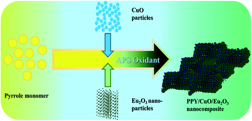 | ||
| Scheme 1 Schematic illustration of PPY/CuO/Eu2O3 nanocomposite by in situ oxidative polymerization of pyrrole. | ||
2.5 Structural and morphological characterizations
The as-synthesized PPY, PPY/CuO, and PPY/CuO/Eu2O3-2 nanocomposites were characterized by FT-IR spectroscopy (Nicolet 6700) in the wavenumber range 400–4000 cm−1. The sample preparation for FT-IR analysis involved mixing spectroscopic grade potassium bromide (KBr) with synthesized materials in the weight ratio of 20![[thin space (1/6-em)]](https://www.rsc.org/images/entities/char_2009.gif) :
:![[thin space (1/6-em)]](https://www.rsc.org/images/entities/char_2009.gif) 1 in an agate mortar and finally casting the mixture into small disk-shaped pellets by applying a load of 5 tons for 2 min. The surface morphologies of nanocomposites were examined using FE-SEM (Supra-55 Carl ZEISS Germany) technique at an accelerating voltage of 5 kV and vacuum of 10−4 to 10−6 mm Hg. The samples were prepared by adhering a small amount of specimen onto a carbon tape followed by thin layer gold coating. HR-TEM images were recorded using JEOL (JEM-2100) machine. For this purpose, approximately 0.5 mg sample was dispersed into 10–15 mL ethanol followed by sonication. From this solution, one drop specimen was taken and placed over the copper grid with the help of a micropipette. Surface area and the pore features of the as-prepared samples were studied using Quanta Chrome Nova-1000 surface analyzer instrument using liquid nitrogen at 77 K. Adsorption–desorption isotherms were recorded to obtain the surface area using BET method and pore size distribution using BJH method. The thermal gravimetric analysis (TGA) was performed using thermogravimetric analyzer (NETZSCH-0798-M) to study the thermal stability of the samples. The samples were heated in the temperature range 30–800 °C at the rate of 10 °C min−1 with continuous nitrogen flow at the rate of 100 mL min−1.
1 in an agate mortar and finally casting the mixture into small disk-shaped pellets by applying a load of 5 tons for 2 min. The surface morphologies of nanocomposites were examined using FE-SEM (Supra-55 Carl ZEISS Germany) technique at an accelerating voltage of 5 kV and vacuum of 10−4 to 10−6 mm Hg. The samples were prepared by adhering a small amount of specimen onto a carbon tape followed by thin layer gold coating. HR-TEM images were recorded using JEOL (JEM-2100) machine. For this purpose, approximately 0.5 mg sample was dispersed into 10–15 mL ethanol followed by sonication. From this solution, one drop specimen was taken and placed over the copper grid with the help of a micropipette. Surface area and the pore features of the as-prepared samples were studied using Quanta Chrome Nova-1000 surface analyzer instrument using liquid nitrogen at 77 K. Adsorption–desorption isotherms were recorded to obtain the surface area using BET method and pore size distribution using BJH method. The thermal gravimetric analysis (TGA) was performed using thermogravimetric analyzer (NETZSCH-0798-M) to study the thermal stability of the samples. The samples were heated in the temperature range 30–800 °C at the rate of 10 °C min−1 with continuous nitrogen flow at the rate of 100 mL min−1.
2.6 Electrochemical measurements
The samples were evaluated using cyclic voltammetry (CV), galvanostatic charge–discharge (GCD), and electrochemical impedance spectroscopic (EIS) techniques so as to investigate their electrochemical performance. Experiments were conducted on symmetric two electrode system (CHI-760D) operated at the room temperature using 1 M H2SO4 as the electrolyte. For this purpose, a mixture of 80 wt% active material, 10 wt% carbon black and, 10 wt% polyvinylidene difluoride (as a binder) was prepared with the addition of a small amount of ethanol to obtain a slurry of the mixture. Approximately, 1 mg of the prepared slurry was pressed on two nickel foams (Changsha Lyrun Material Co., Ltd. China), each of dimension 1 × 1 cm2, serving as current collectors. The weight of the nickel foams was noted before and after mass loading and the mass difference gave the amount of loading. Finally, both the nickel foams coated with the slurry were dried at 90 °C overnight in the oven to obtain the symmetric electrodes for conducting the experiment.3. Results and discussions
3.1 Structural and morphological characterization
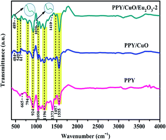
The chemical structure and the presence of chemical interactions between the various constituents of the nanocomposites were investigated by FT-IR vibrational spectra. Fig. 1 represents the FT-IR spectra of the nanocomposites and the as-synthesized PPY. The absorption peaks at 1555, 1457, 1373, and 1196 cm−1 corresponded to C![[double bond, length as m-dash]](https://www.rsc.org/images/entities/char_e001.gif) C stretching, C–N stretching, C–H vibrations, and C–C stretching respectively.34,35 The absorption peaks at 1050 cm−1 appeared due to in-plane distortion of C–H bond, and N–H bond belonged to the pyrrole ring, while the peak at 925 cm−1 appeared due to C–C out of phase deformation vibration.35 The out of ring deformation and C–C out of plane ring deformation or C–H rocking peaks appeared at 794 and 665 cm−1 respectively.35 All these peaks also appeared in the case of the PPY/CuO and PPY/CuO/Eu2O3-2 ternary nanocomposite along with slight shifts in the peaks suggestive of developed interactions between various species present in the nanocomposites. Further, the peaks at 484, 549, and 617 cm−1 appeared in the case of PPY/CuO which represented the vibrations of Cu–O bond.36,37 However, the new absorption peak at 489 cm−1 corresponding to the characteristic Eu–O bond, together with the peaks at 1020 and 1410 cm−1 indicated the presence of Eu2O3 in the PPY/CuO/Eu2O3-2 ternary nanocomposite.38,39 Also, the inflation of the absorption hump at 3430 cm−1 for the incorporation of CuO and then Eu2O3 in the PPY/CuO and PPY/CuO/Eu2O3-2 ternary nanocomposite indicated the presence of hygroscopic materials in the nanocomposite. Since CuO and Eu2O3 are both hygroscopic in nature, the inflation of the peak was an indication towards the addition CuO and Eu2O3.
C stretching, C–N stretching, C–H vibrations, and C–C stretching respectively.34,35 The absorption peaks at 1050 cm−1 appeared due to in-plane distortion of C–H bond, and N–H bond belonged to the pyrrole ring, while the peak at 925 cm−1 appeared due to C–C out of phase deformation vibration.35 The out of ring deformation and C–C out of plane ring deformation or C–H rocking peaks appeared at 794 and 665 cm−1 respectively.35 All these peaks also appeared in the case of the PPY/CuO and PPY/CuO/Eu2O3-2 ternary nanocomposite along with slight shifts in the peaks suggestive of developed interactions between various species present in the nanocomposites. Further, the peaks at 484, 549, and 617 cm−1 appeared in the case of PPY/CuO which represented the vibrations of Cu–O bond.36,37 However, the new absorption peak at 489 cm−1 corresponding to the characteristic Eu–O bond, together with the peaks at 1020 and 1410 cm−1 indicated the presence of Eu2O3 in the PPY/CuO/Eu2O3-2 ternary nanocomposite.38,39 Also, the inflation of the absorption hump at 3430 cm−1 for the incorporation of CuO and then Eu2O3 in the PPY/CuO and PPY/CuO/Eu2O3-2 ternary nanocomposite indicated the presence of hygroscopic materials in the nanocomposite. Since CuO and Eu2O3 are both hygroscopic in nature, the inflation of the peak was an indication towards the addition CuO and Eu2O3.
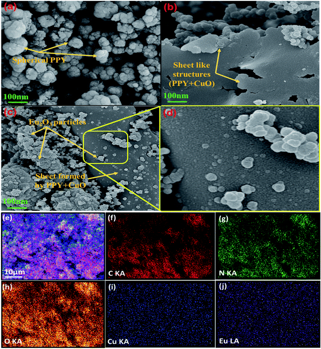
The morphological properties and the distribution of various species in the samples were investigated using FE-SEM as shown in Fig. 2. Pure polypyrrole acquired spherical structures showing some agglomeration as represented in Fig. 2a. Fig. S2(a and b)† represented the FE-SEM images of pristine CuO and Eu2O3 nanopowder. It was assessed from Fig. S2(a)† that CuO particles were of about 100 nm and Eu2O3 nanoparticles had dimensions of few nanometers as seen in Fig. S2(b).† Incorporation of CuO in PPY resulted in the formation of composite acquiring sheet-like morphology as shown in Fig. 2b. The uniform distribution of CuO particles in the PPY matrix increased the porosity and resulted in the formation of a conducting network for charge transfer. The mesoporous conducting network hence formed could be expected to facilitate the absorption of more ions from the electrolyte in turn enhancing the specific capacitance value.40 The Eu2O3 particles got distributed over the sheet-like PPY–CuO composite as could be clearly perceived in the Fig. 2(c and d). The resulting distribution of the components in the PPY/CuO/Eu2O3-2 ternary nanocomposite was further investigated by energy-dispersive X-ray spectroscopy (EDS) mapping technique, which clearly showed a homogeneous and continuous distribution of the constituent (C, N, O, Cu, and Eu) elements as represented by the Fig. 2(e–j).
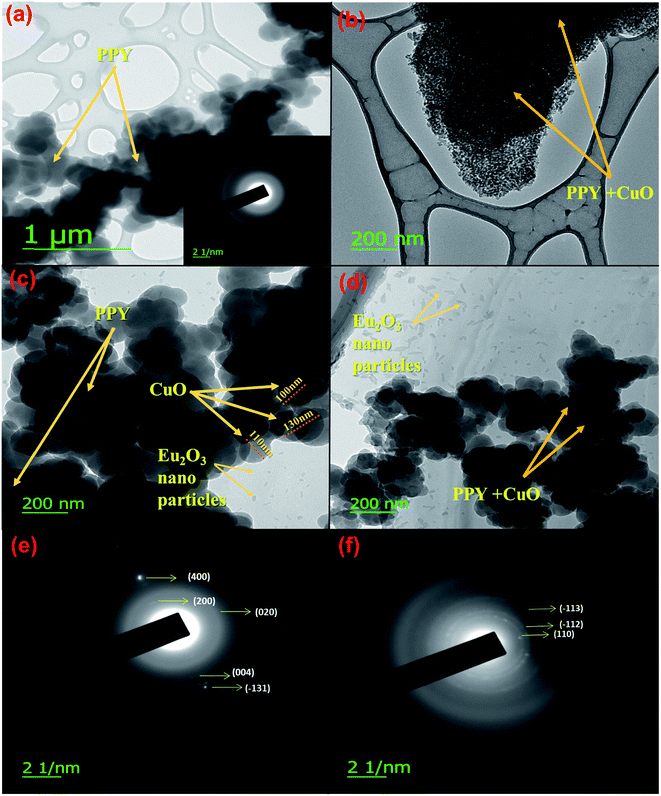
To further characterize the morphological and structural features of the samples, these were analyzed using HR-TEM, as shown in the Fig. 3. Fig. 3a represented the HR-TEM image for pure PPY, where polypyrrole chains could be clearly perceived as deep gray structures. HR-TEM image of PPY/CuO, as shown in Fig. 3b presented numerous small structures making a continuous network of PPY/CuO composite.41,42 Eu2O3 seemed to possess nano-size random structures as shown in Fig. 3(c and d).43 The particle size of CuO was roughly estimated to be around 110 nm in the PPY/CuO/Eu2O3-2 ternary nanocomposite as shown in Fig. 3(c). Also, Eu2O3 nanoparticles were observed as small dots as shown in Fig. 3(c and d). SAED patterns for PPY/CuO and PPY/CuO/Eu2O3-2 have been depicted in the Fig. 3(e and f). The blurred ring-like patterns along with the appearance of some bright spots suggested that both the PPY/CuO and PPY/CuO/Eu2O3-2 ternary nanocomposite were semi-crystalline in nature. In the case of PPY/CuO the reflections occurred from 400, 200, 020, 004, and −131 planes. While, reflections were perceived to occur from −113, −112, and 110 planes in case of the PPY/CuO/Eu2O3-2 ternary nanocomposite. The SAED pattern for pure PPY has been shown in the inset with the HR-TEM image for pure PPY. The blurred ring-like structures indicated amorphous nature of the pure PPY.22
3.2 Brunauer–Emmett–Teller (BET) analysis
Nitrogen adsorption and desorption isotherms were obtained at 77 K to investigate the specific surface area and porosity of the as-prepared polymeric samples. As shown in Fig. 4a, pure PPY, PPY/CuO, and PPY/CuO/Eu2O3-2 ternary nanocomposite exhibited type IV isotherms with the H3 type of hysteresis loop (as per the IUPAC classification norms) without any adsorption saturation region, indicating the presence of mesoporous adsorbent.44 The isotherms illustrated that the incorporation of inorganic fillers had no effect on the mesoporous nature of the as-prepared nanocomposite. For further confirmation, the pore size distribution plots were obtained based on the adsorption data according to the BJH method as shown in the Fig. 4b.45,46 The specific surface area and pore diameter of neat PPY were 41 m2 g−1 and 5.25 nm. The specific surface area increased to 81.7 and 107.5 m2 g−1, while the pore diameter decreased to 4.15 and 3.6 nm for PPY/CuO and PPY/CuO/Eu2O3-2 ternary nanocomposite respectively. The enhancement in the specific surface area could be attributed to the inclusion of the metal oxides CuO and Eu2O3 into the mesoporous PPY matrix. Addition of Eu2O3 nanoparticles increased the specific surface area of the resulting nanocomposite, owing to the greater surface to volume ratio of the nanostructures. The resulting nanocomposite remained mesoporous in nature. However, there was a significant reduction in the pore size of the resulting nanocomposite. In addition, incorporation of inorganic fillers in the PPY matrix led to the formation of mesoporous conductive network facilitating an easy path for the charge transport. The desorption loops for both pure PPY and the PPY/CuO/Eu2O3-2 ternary nanocomposite showed a slight change in the slope at the relative pressure of 0.4. The terminations of the desorption curves were noted to be around P/P0 = 0.35. For the PPY/CuO composite, the desorption terminated at the starting point of the adsorption phenomenon.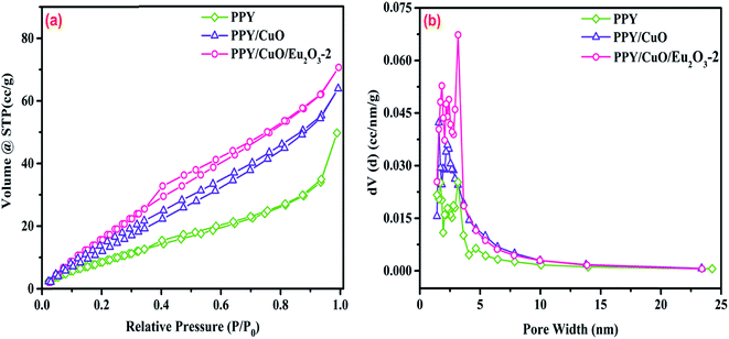 | ||
| Fig. 4 (a) N2 adsorption–desorption isotherms for the pure PPY, PPY/CuO, and PPY/CuO/Eu2O3-2 ternary nanocomposite and (b) BJH pore size distribution plots for the prepared samples. | ||
3.3 Thermogravimetric analysis
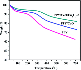
To investigate the influence of the inorganic fillers CuO and Eu2O3 on the thermal stability of the polymer matrix, TGA technique was employed. The obtained thermograms have been shown in the Fig. 5. It was observed that all the samples exhibited two-step degradation process. The first weight loss, at around 100 °C, could be attributed due to the evaporation of the moisture and other the volatile impurities in the sample.7,22 The second degradation occurred at a higher temperature, around 300–500 °C, which could be attributed mainly due to the obliteration of the backbone of the polymer chains.22 It is evident that the inclusion of CuO in PPY matrix enhanced the thermal stability of the polymer, which was augmented by the presence of Eu2O3 in the PPY/CuO/Eu2O3-2 ternary nanocomposite. PPY/CuO/Eu2O3-2 ternary nanocomposite retained 82.5% of initial weight as compared to 75% and 64% for the binary and the pure PPY respectively at 650 °C. The detailed weight loss% at various temperatures has been shown in the Table 2. The amount of CuO present in the PPY/CuO, and Eu2O3 present in the PPY/CuO/Eu2O3-2 ternary nanocomposite was verified from the weight retention data corresponding to the TGA.47 It was observed that at 650 °C amount of PPY residue was 64%. On the other hand, PPY/CuO retained 75%, and the PPY/CuO/Eu2O3-2 ternary nanocomposite retained 82.5% of the initial weight at 650 °C. Thus, if ‘x’ was the wt% of CuO in the PPY/CuO nanocomposite, heating at 650 °C would cause CuO (x) and the residual portion of PPY to be left. Hence, we obtained x + 0.64(1 − x) = 0.75. Calculating accordingly, the amount of CuO in the PPY/CuO nanocomposite was calculated to be 30% (weight%). Similar calculations for the PPY/CuO/Eu2O3-2 ternary nanocomposite confirmed that the amount of Eu2O3 present in the PPY/CuO/Eu2O3-2 ternary nanocomposite was 30% (weight%) of the total content.| Sample | Weight loss% at 100 °C | Weight loss% at 200 °C | Weight loss% at 300 °C | Weight loss% at 400 °C | Weight retention% at 650 °C |
|---|---|---|---|---|---|
| Pure PPY | 7 | 9 | 18 | 26 | 64 |
| PPY/CuO | 6 | 7 | 10 | 17 | 75 |
| PPY/CuO/Eu2O3-2 | 4 | 5 | 6 | 10 | 82.5 |
3.4 Electrochemical measurements
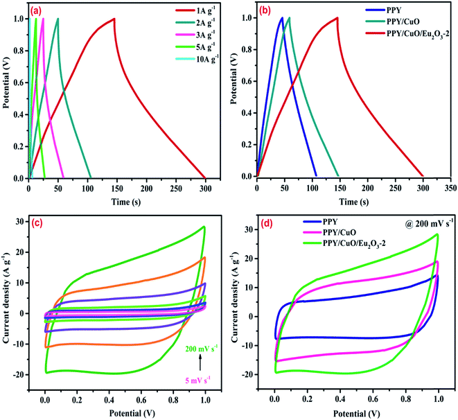
The electrochemical performance of the as-prepared samples was investigated using a symmetrical two electrode system in 1 M H2SO4 as the electrolyte.7,22,48 The GCD measurements for the PPY/CuO/Eu2O3-2 was performed within a potential window 0–1 V with varying current densities from 1–10 A g−1. The GCD plots as shown in Fig. 6a, implied a decent reversible pseudocapacitive behavior exhibited by the ternary nanocomposite in a wide current range. As depicted in Fig. 6b, the GCD curves for pure PPY, measured at 1 A g−1, seemed to exhibit non-triangular nature showing an ideal pseudocapacitive behavior. The GCD curves for PPY/CuO and PPY/CuO/Eu2O3-2 ternary nanocomposite also showed significant deviation from triangular path, revealing the pseudocapacitive dominance arriving from the incorporation of the metal oxides in the PPY matrix. As seen from Fig. 6b, charging and discharging time for PPY/CuO/Eu2O3-2 were witnessed to increase, as compared to the PPPY and PPY/CuO, indicating an enhancement in the specific capacitance of the ternary nanocomposite. Specific capacitance derived from galvanostatic charging–discharging measurements were calculated according to the equation:22,48| Cs = 2IΔt/mΔV | (1) |
| Electrode material | Specific capacitance (F g−1) | Condition | Energy density (W h kg−1) | Power density (W kg−1) | References |
|---|---|---|---|---|---|
| PPY/CuO | 28 | 5 mV s−1 | — | — | 50 |
| POAP/Eu2O3 | 375 | 100 mV s−1 | — | — | 31 |
| PPY/graphene nanosheets/Eu3+ | 238 | 1 A g−1 | — | — | 32 |
| PPY/YAG:Al5Y3O12 | 254 | 25 mV s−1 | — | — | 51 |
| PPY/CuO | 174 | 1 A g−1 | 6.03 | 2618 | Our work |
| PPY/CuO/Eu2O3-2 | 320 | 1 A g−1 | 11.1 | 3147 | Our work |
| PPY/CuO/Eu2O3-1 | 238 | 1 A g−1 | 1.94 | 2523 | Our work |
| PPY/CuO/Eu2O3-3 | 201 | 1 A g−1 | 2.38 | 2500 | Our work |
The CV curves for the PPY/CuO/Eu2O3-2 ternary nanocomposite, as shown in Fig. 6c, were plotted in the working potential range 0–1 V with the varying scan rates of 5, 10, 20, 50, 100, and 200 mV s−1. Pure PPY, PPY/CuO, and PPY/CuO/Eu2O3-2 ternary nanocomposite were seemed to possess distorted rectangular CV profiles indicative of an ideal pseudocapacitive nature as perceived from Fig. 6d. The CV curves for the PPY/CuO/Eu2O3-2 ternary nanocomposite demonstrated a good and stable pseudocapacitive behavior at the various scan rates with a working potential of 1 V. Further, it showed the largest integrated area under the CV loop as compared to the pure PPY and PPY/CuO. The enhanced area under the CV loops for the PPY/CuO/Eu2O3-2 ternary nanocomposite suggested the improved specific capacitance as the integrated area under the CV curve is directly proportional to the specific capacitance value exhibited by the electrode material. The absence of any peak for the CV loops for the samples was an indication towards charging and discharging at a pseudo-constant rate over the complete voltammetric cycle. Also, for PPY/CuO/Eu2O3-2 ternary nanocomposite, the current response in the oxidation half was witnessed to shift positively, while current response for the reduction half was witnessed to shift negatively with an increasing scan rate. It happened mainly due to the variation in the thickness of diffusion layer formed with varying scan rates.52
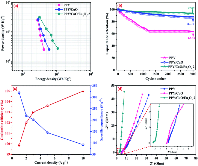
Further, a graphical comparison between the specific capacitance values for the pure PPY, PPY/CuO, and PPY/CuO/Eu2O3-2 ternary nanocomposite at different current densities has been shown in Fig. 7. At the maximum current density of 10 A g−1, the ternary nanocomposite was witnessed to retain a considerable value of specific capacitance i.e. 92 F g−1. While, pure PPY and PPY/CuO showed a significant reduction reaching the values of 79 and 84 F g−1 at the current density of 10 A g−1. This decrease in the capacitance value with an increase in the current density could be due to the inadequate time for the accomplishment of the doping/dedoping process. This led to the participation of only the outer surface of the electrode material where the redox reaction took place. However, at the lower current densities ions from electrolyte could reach into the bulk and hence almost all the pores of the electrode material, ultimately resulting into an enhanced specific capacitance value.53,54
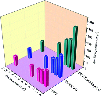 | ||
| Fig. 7 Comparison of the specific capacitances of PPY, PPY/CNT and PPY/CuO/Eu2O3-2 nanocomposites at the various current densities. | ||
An electrode material should impart appreciably high energy density as well as high power density for successful fabrication of high-performance supercapacitor. Specific energy density (E) and specific power density (P) for the samples were calculated from the GCD data using the equations.22,48
| E = 1/8CV2 | (2) |
| P = E/Δt | (3) |
The capacitance retention analysis for determining the robustness and durability was carried out by subjecting the samples to the charge–discharge process for 3000 cycles, the corresponding results have been shown in Fig. 8b. Pure PPY suffered poor cyclic performance caused by swelling and shrinkage during the charge–discharge cycle. It showed only 62.83% capacitance retention after 3000 cycles. However, the PPY/CuO/Eu2O3-2 ternary nanocomposite incorporated with inorganic fillers (CuO and Eu2O3) has endured 3000 charge–discharge cycles with 92.89% capacitance retention which was almost 1.4 times larger than the pure PPY. This enhanced cyclic stability could be attributed to the resulting “skeleton/skin” structure providing a stronger backbone to the PPY/CuO/Eu2O3-2 ternary nanocomposite.
As far as the practical application is concerned, an electrode material should exhibit a considerably high coulombic efficiency. For the PPY/CuO/Eu2O3-2 ternary nanocomposite, the coulombic efficiency was calculated using the following equation.55
| η = td/tc | (4) |
In the equation, td (s) represented discharging time, and tc (s) represented charging time. As shown in Fig. 8c, the coulombic efficiency was noted to increase with a fading capacitance when current density was increased from 1 to 10 A g−1. It reached a value of 99.86% at the current density of 1 A g−1. Such high value of coulombic efficiency established the improved redox reversibility of the PPY/CuO/Eu2O3-2 ternary nanocomposite. With a further increase in the current density to 10 A g−1, the value for coulombic efficiency crossed 100% and reached a value of 105%. The coulombic efficiency of more than 100% could be explained by the occurrence of some parasitic reactions such as degradation of electrode and electrolyte leading to the addition of more charges during the discharge process. A high coulombic efficiency as well as well as an excellent cycle stability revealed the efficiency of the PPY/CuO/Eu2O3-2 ternary nanocomposite for application in high-performance supercapacitors.56
The internal resistance, charge transfer kinetics and the ion diffusion processes were investigated by the EIS measurement in the frequency range 0.1 Hz to 100 kHz with an amplitude of 5 mV applied at an open circuit potential together with an AC perturbation. As shown in the Fig. 8d, the Nyquist plots for all the samples consisted of two parts: a small semicircular portion and a linear region. The intercept of the semicircle with Z′-axis in the higher frequency region represented the contact resistance, electrolyte resistance, and inherited resistance offered by the active material.1 This is termed as equivalent series resistance (Rs), while the diameter of the semicircle represented the charge transfer resistance (Rct) offered by the electrode material to the transport of electrons through it. The linear portion represented the Warburg resistance and the angle it made with the Z′-axis indicated about the diffusion resistance offered by the electrode material to the redox element from the electrolyte.4 The PPY/CuO/Eu2O3-2 ternary nanocomposite was witnessed to exhibit the least intercept at the Z′-axis and the smallest semicircle, indicative of the higher ion and electron conductivity. Moreover, the steepest Warburg region displayed by PPY/CuO/Eu2O3-2, as compared to the pure PPY and the PPY/CuO nanocomposite, indicated an ideal capacitive behavior exhibited by the ternary nanocomposite. The Rs values obtained for the pure PPY, PPY/CuO and PPY/CuO/Eu2O3-2 ternary nanocomposites were 5.38, 5.0 and 2.4 Ω. It was noteworthy that the Rs value for the PPY/CuO/Eu2O3-2 ternary nanocomposite got halved as compared to the pure PPY. This result could be well related to the observed porosity as obtained from the BET analysis. Highest porosity was observed for the PPY/CuO/Eu2O3-2 ternary nanocomposite, leading to the lowest resistance offered. This could be attributed to the large number of interconnected pores, in turn, paving an easy path for the ion and electron transport, and hence showing an enhancement in the specific capacitance value.57
4. Conclusions
Incorporation of rare earth metal oxide (Eu2O3) proves very effective in increasing the capacitive performances of the PPY/CuO composite. The PPY/CuO/Eu2O3-2 ternary nanocomposite was witnessed to exhibit an enhanced specific capacitance value (320 F g−1 at the current density of 1 A g−1), together with a markedly enhanced thermal and cyclic stability. It was noteworthy that increasing the Eu2O3 content beyond a certain limit (30 weight% of Eu2O3) resulted in a deterioration of the specific capacitance value of the composite. This design provides a simple strategy to develop electrode material with enhanced stability, coulombic efficiency and excellent electrochemical properties for high-performance supercapacitors.Acknowledgements
Authors acknowledge the Indian Institute of Technology (Indian school of mines), Dhanbad, India for extending constant support for this work.References
- Springer Science & Business Media, Conway, 1999, DOI:10.1007/978-1-4757-3058-6.
- P. Simon and Y. Gogotsi, Nat. Mater., 2008, 7, 845–854 CrossRef CAS PubMed.
- Y. G. Wang, Z. D. Wang and Y. Y. Xia, Electrochim. Acta, 2005, 50, 5641–5646 CrossRef CAS.
- G. Wang, L. Zhang and J. Zhang, Chem. Soc. Rev., 2012, 41, 797–828 RSC.
- M. Inagaki, H. Konno and O. Tanaike, J. Power Sources, 2010, 195, 7880–7903 CrossRef CAS.
- T. Cottineau, M. Toupin, T. Delahaye, T. Brousse and D. Belanger, Appl. Phys. A: Mater. Sci. Process., 2006, 82, 599–606 CrossRef CAS.
- A. K. Thakur and R. B. Choudhary, Synth. Met., 2016, 220, 25–33 CrossRef CAS.
- M. Liu, M. Shi, W. Lu, D. Zhu, L. Li and L. Gan, Chem. Eng. J., 2017, 313, 518–526 CrossRef CAS.
- S. Ye and J. Feng, ACS Appl. Mater. Interfaces, 2014, 6, 9671–9679 CAS.
- L. Miao, H. Duan, M. Liu, W. Lu, D. Zhu, T. Chen, L. Li and L. Gan, Chem. Eng. J., 2017, 317, 651–659 CrossRef CAS.
- J. Kim, J. Lee, J. You, M. S. Park, M. S. A. Hossain, Y. Yamauchi and J. H. Kim, Mater. Horiz., 2016, 3, 517–535 RSC.
- M. Mastragostino, C. Arbizzani and F. Soavi, Solid State Ionics, 2002, 148, 493–498 CrossRef CAS.
- N. K. Guimard, N. Gomez and C. E. Schmidt, Prog. Polym. Sci., 2007, 32, 876–921 CrossRef CAS.
- M. Mastragostino, R. Paraventi and A. Zanelli, J. Electrochem. Soc., 2000, 14, 3167 CrossRef.
- M. Mastragostino, C. Arbizzani, L. Meneghello and R. Paraventi, Adv. Mater., 1996, 8, 331–334 CrossRef.
- T. G. Yun, B. I. Hwang, D. Kim, S. Hyun and S. M. Han, ACS Appl. Mater. Interfaces, 2015, 7, 9228–9234 CAS.
- F. Yang, M. Xu, S. J. Bao and Q. Q. Sun, RSC Adv., 2014, 4, 33569 RSC.
- X. Hu, W. Xiong, W. Wang, S. Qin, H. Cheng, Y. Zeng, B. Wang and Z. Zhu, ACS Sustainable Chem. Eng., 2016, 4, 1201–1211 CrossRef CAS.
- B. Anothumakkool, R. Soni, S. Bhange and S. Kurungot, Energy Environ. Sci., 2015, 8, 1339–1347 CAS.
- H. Zhang, Z. Hu, M. Li, L. Hu and S. Jiao, J. Mater. Chem. A, 2014, 2, 17024–17030 CAS.
- Z. H. Dong, Y. L. Wei, W. Shi and G. A. Zhang, Mater. Chem. Phys., 2011, 131, 529–534 CrossRef CAS.
- A. K. Thakur, R. B. Choudhary, M. Majumder, G. Gupta and M. V. Shelke, J. Electroanal. Chem., 2016, 782, 278–287 CrossRef CAS.
- G. A. Snook, P. Kao and A. S. Best, J. Power Sources, 2011, 196, 1–12 CrossRef CAS.
- Y. T. Kim, K. Tadai and T. Mitani, J. Mater. Chem., 2005, 15, 4914–4921 RSC.
- J. Shaikh, R. Pawar, N. Tarwal, D. Patil and P. Patil, J. Alloys Compd., 2011, 25, 7168–7174 CrossRef.
- A. E. Fischer, K. A. Pettigrew, D. R. Rolison, R. M. Stroud and J. W. Long, Nano Lett., 2007, 7, 281–286 CrossRef CAS PubMed.
- S. K. Shinde, D. P. Dubal, G. S. Ghodake and V. J. Fulari, RSC Adv., 2015, 5, 4443–4447 RSC.
- K. Krishnamoorthy and S.-J. Kim, Mater. Res. Bull., 2013, 48, 3136–3139 CrossRef CAS.
- S. E. Moosavifard, M. F. El-Kady, M. S. Rahmanifar, R. B. Kaner and M. F. Mousavi, ACS Appl. Mater. Interfaces, 2015, 7, 4851–4860 CAS.
- S. Peng, L. Fan, W. Rao, Z. Bai, W. Xu and J. Xu, J. Mater. Sci., 2017, 52, 1930–1942 CrossRef CAS.
- H. M. Shiri and A. Ehsani, J. Colloid Interface Sci., 2016, 473, 126–131 CrossRef PubMed.
- W. Sun and Z. Mo, Mater. Sci. Eng., B, 2013, 178, 527–532 CrossRef CAS.
- Z. Yin, Y. Ding, Q. Zheng and L. Guan, Electrochem. Commun., 2012, 20, 40–43 CrossRef CAS.
- D. P. Dubal, S. V. Patil, W. B. Kim and C. D. Lokhande, Mater. Lett., 2011, 65, 2628–2631 CrossRef CAS.
- D. P. Dubal, S. H. Lee, J. G. Kim, W. B. Kim and C. D. Lokhande, J. Mater. Chem., 2012, 22, 3044–3052 RSC.
- D. P. Dubal, D. S. Dhawale, R. R. Salunkhe, V. S. Jamdade and C. D. Lokhande, J. Alloys Compd., 2010, 492, 26–30 CrossRef CAS.
- A. Pendashteh, M. F. Mousavi and M. S. Rahmanifar, Electrochim. Acta, 2013, 88, 347–357 CrossRef CAS.
- H. Yang, D. Zhang, L. Shi and J. Fang, Acta Mater., 2008, 56, 955–967 CrossRef CAS.
- S. Bera, M. Ghosh, M. Pal, N. Das, S. Saha, S. K. Dutta and S. Jana, RSC Adv., 2014, 4, 37479–37490 RSC.
- L. Y. Ng, A. W. Mohammad, C. P. Leo and N. Hilal, Desalination, 2013, 308, 15–33 CrossRef CAS.
- Z. Guo, X. Liang, T. Pereira, R. Scaffaro and H. T. Hahn, Compos. Sci. Technol., 2007, 67, 2036–2044 CrossRef CAS.
- G. Ren, D. Hu, E. W. C. Cheng, M. A. Vargas-Reus, P. Reip and R. P. Allaker, Int. J. Antimicrob. Agents, 2009, 33, 587–590 CrossRef CAS PubMed.
- Y. Li, M. Ge, J. Li, J. Wang and H. Zhang, CrystEngComm, 2011, 13, 637–641 RSC.
- S. Hu, L. Ma, J. You, F. Li, Z. Fan, F. Wang, D. Liu and J. Gui, RSC Adv., 2014, 4, 21657–21663 RSC.
- J. Zhang, P. Chen, B. H. L. Oh and M. B. C. Park, Nanoscale, 2013, 5, 9860–9866 RSC.
- N. B. Nayak and B. B. Nayak, Sci. Rep., 2016, 6, 26404 CrossRef CAS PubMed.
- J. Wang, Z. Wu, K. Hu, X. Chen and H. Yin, J. Alloys Compd., 2015, 619, 38–43 CrossRef CAS.
- I. Karbhal, R. R. Devarapalli, J. Debgupta, V. K. Pillai, P. M. Ajayan and M. V. Shelke, Chem.–Eur. J., 2016, 22, 7134–7140 CrossRef CAS PubMed.
- J. Wang, C. Zhang, Z. Liu, K. Ding and Z. Yang, Macromol. Rapid Commun., 2006, 27, 787–792 CrossRef.
- M. Ates, M. A. Serin, I. Ekmen and Y. N. Ertas, Polym. Bull., 2015, 72, 2573–2589 CrossRef CAS.
- H. M. Shiri, A. Ehsani and J. S. Shayeh, RSC Adv., 2015, 5, 91062–91068 RSC.
- M. Alam, K. Karmakar, M. Pal and K. Mandal, RSC Adv., 2016, 6, 114722–114726 RSC.
- P. Nazish, N. Mahato, M. O. Ansari and M. H. Cho, Composites, Part B, 2016, 87, 281–290 CrossRef.
- M. Jin, G. Han, Y. Chang, H. Zhao and H. Zhang, Electrochim. Acta, 2011, 56, 9838–9845 CrossRef CAS.
- X. Xifeng, Q. Hao, W. Lei, W. Wang, H. Wang and X. Wang, J. Mater. Chem., 2012, 22, 8314–8320 RSC.
- X. Liu, T. Wu, Z. Dai, K. Tao, Y. Shi and C. Peng, et al., J. Power Sources, 2016, 307, 208–213 CrossRef CAS.
- X. Wei, X. Jiang, J. Wei and S. Gao, Chem. Mater., 2016, 28, 445–458 CrossRef CAS.
Footnote |
| † Electronic supplementary information (ESI) available. See DOI: 10.1039/c7ra01438d |
| This journal is © The Royal Society of Chemistry 2017 |

